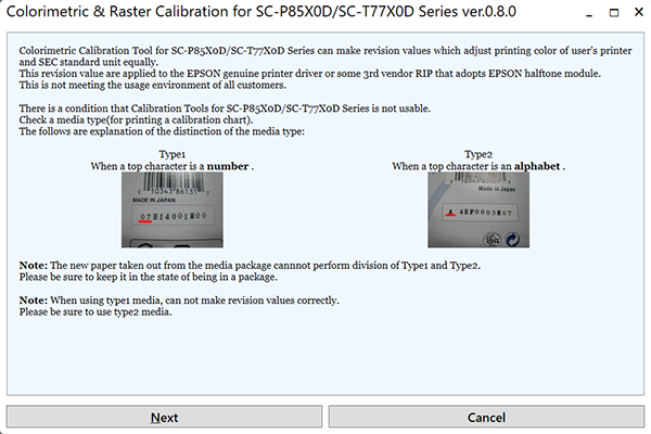
Colorimetric & Raster Calibration
Adjustment Overview
Carry out this adjustment when users request reduction of tone variation between their printers and pages.
- Print Head
- Main Board (NVRAM backup NG)
- Power Supply Board
Purpose
By registering/controlling information concerning the ink droplets, this product improves calibration accuracy and ensures stable color quality. (Difference in color among individual products or each mode is reduced.)
Principle
The calibration is performed by measuring a printed correction pattern with a calibrator. ID information that is calculated based on the acquired color values (L*, a*, b*) is transmitted to the printer driver, and the printer driver corrects the dot generation amount for each dot size x each color in the print data.
Adjusting Method
Required Tools
| Lubrication Tool | Application/Specification |
|---|---|
| Plain paper (A4 / Letter or larger size, roll paper is acceptable) | For nozzle check |
EPSON Enhanced (Archival) Matte Paper (A3/Tabloid (11×17 inch)) (x2) | For printing charts |
| Computer | Following drivers should be installed beforehand. Printer driver for this product Printer driver for this product Supported OS: Windows 7 (64bit), Windows 10 (64bit) |
Colorimetric & Raster Calibration Application | Colorimetric & Raster Calibration for SC-P8500D/SC-T7700D Series |
| Calibrator | With UV filter |
Calibration plate (White plate) | Accessory provided with the calibrator |
| Scanning ruler (Scale) | Accessory provided with the calibrator |
| USB cable | To connect the computer and the calibrator |
| White sheet (should be larger than A3+) | Uses when there is not the Calibration plate. |
Adjustment Workflow
The workflow of the adjustment is explained in this section.
START
![]()
Cleaning
![]()
Nozzle Check
![]()
Alignment check
![]()
Print calibration chart
![]()
Measure color
![]()
Write the color ID
![]()
END
Adjustment Procedure
- Turn the printer power on.
- From the left tab of the Service Program, select Colorimetric & Raster Calibration.
- Make sure the printer is in the ready state, and click [Next].
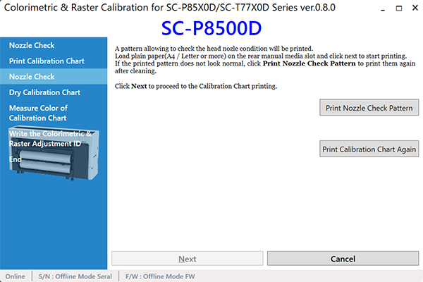
- Load plain paper in the size of A4/Letter or larger into the paper slot, and feed it with the operation panel operation.
- Click [Print Nozzle Check Pattern] to print the nozzle check pattern.
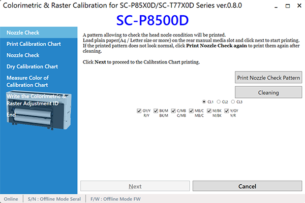
Check the nozzle pattern. If there is any defect, execute the cleaning using the Service Program.
 Caution / 注意
Make sure to confirm that there is no dot missing for all nozzles before executing Colorimetric Calibration Adjustment.
- Set the paper again.
Click [Print Nozzle Check again] to print the nozzle check pattern. If the check pattern is appropriate, click [Next].
Caution / 注意If a nozzle is clogged, color measurement may fail and adjustment may not be performed correctly. Click [Print Calibration Chart again] and then perform cleaning. Repeat this process until the calibration chart can be printed without any nozzle clogging.
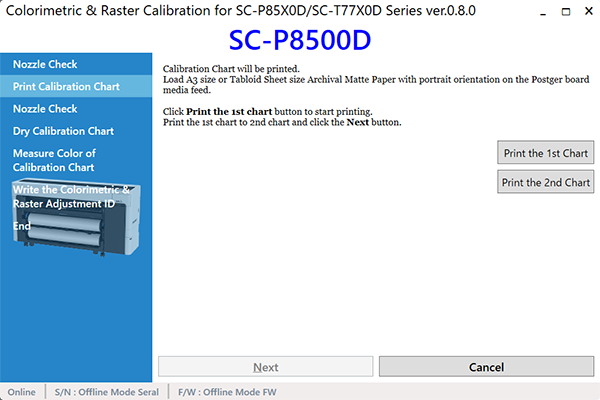
Load the Enhanced (Archival) Matte Paper in the size of A3/Tabloid (11×17 inch) into the poster board support, and feed it with the operation panel operation.
Caution / 注意When using Tabroid (11 x 17 inch) size EPSON Enhanced (Archival) Matte Paper for printing correction charts, numerical characters may be cut off if the media is not set correctly.
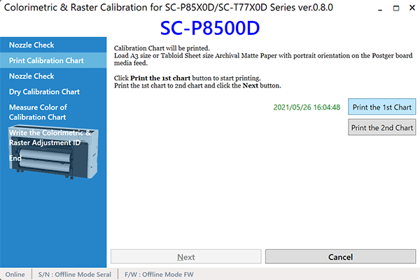
- Click [Next] and then [Print 1st Calibration Chart], and print calibration chart 1.
- Load the Enhanced (Archival) Matte Paper in the size of A3/Tabloid (11×17 inch) into the poster board support, and feed it with the operation panel operation.
- Click [Next] and then [Print 2nd Calibration Chart], and print calibration chart 2.
- Click [Next], load plain paper larger than A4/Letter size in the manual insertion slot.
- Click [Next] to print the nozzle check pattern.
- When there is no nozzle clogging: Dry it for five minutes as is while keeping the calibration chart untouched.
- When there is any nozzle clogging: Click [Print Calibration Chart again], and then go back to step 6.
- When the calibration chart dries out (after five minutes), click [Next].
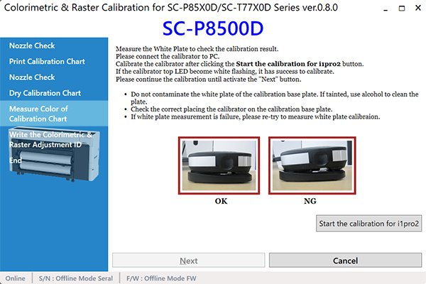
- Connect a calibrator to the computer.
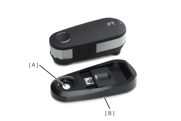
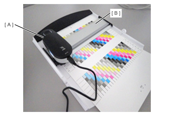
- Measure the white plate (A) to check the calibration result. Correctly load the Color Measurement Device on the calibration base plate (B), and click [Start Calibration of i1Pro2].
 Caution / 注意
- Do not contaminate the white plate of the calibration base plate. If tainted, use alcohol to clean the plate.
- Make sure that the Color Measurement Device is fitting inside the calibration base plate without any gaps.
- If calibration fails, measure the white plate again.
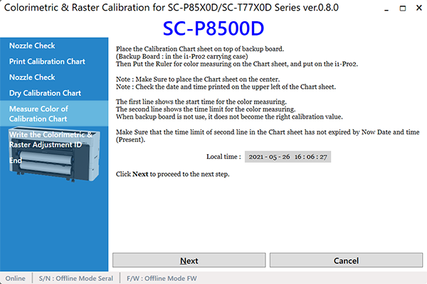
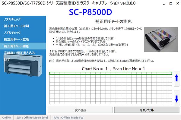
- Click [Next], make sure that the date and time displayed at "Current Time" at the bottom half of the screen is within the period (possible color measurable time) printed on the calibration chart, and then click [Next] again. If the date and time are outside the period, click [Cancel] to return to step 1.
 Caution / 注意
For the print calibration chart, use one that was printed within one week.
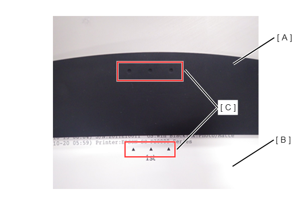
- Set the chart on the base plate with “1st” on the calibration chart 1 on the top.

 Check Point / チェックポイント
Align the marks (C) on the calibration chart (B) with those on the base plate (A).
- Click [Next].
- See below, and set the calibrator (A) and scanning ruler (B) to the 1st row.
- Perform color measuring following procedure.
- Press down the button on the side of the calibrator.
- When the light of the Color Measurement Device changes color to white, the green light starts to flash in the operation direction. For this reason, scanning is performed up to the color measurement end position (edge section) on the right side, along the color measurement guide while the button is kept held down.
- Once the measuring is completed, release the button.
- Press and hold the button again and scan the chart along the scanning ruler to the end position (margin) on the left.
Repeat step 1 to step 4.
Caution / 注意When measuring colors, pay attention to the instructions below.
- Scan one line between five to ten seconds.
- Keep the scan speed constant as possible.
- Measure each of the lines once. (Measure the line as instructed on the program screen.)
- Place the chart on a flat surface. The calibrator and the ruler must be attached firmly to the chart in order to measure the colors accurately.
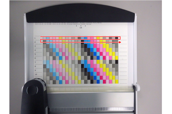
- Do not scan any places other than the one shown in figure below.
- If the read data greatly deviates from the standard values, red frame lines appear. When red frame lines appear, check the above instructions and perform color measurement again.
- When the measurement is complete successfully, the colors of the line on the display become thicker.
- Repeat step 22 for up to the 12th line.
- When measurement is finished for the 12th line, click [Next].
- Fine adjustment pattern
- Turn the calibration chart 1 upside down, and set the chart to the base plate with “2nd” on the top.
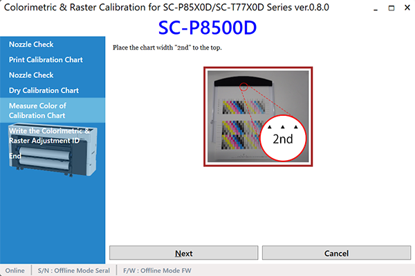 Check Point / チェックポイント
Align the marks (C) on the calibration chart (B) with those on the base plate (A).
- Click [Next].
- Referring to step 22, measure the lines from the first one to 19th.
- Once all the lines are measured, click [Next].
- See the popup dialog and set the chart on the base plate with “3rd” on the calibration chart 2 on the top.
 Check Point / チェックポイント
Align the marks (C) on the calibration chart (B) with those on the base plate (A).
- Click [Next].
- See the figure, and set the calibrator and scanning ruler to the 20th row.
- Referring to step 22, measure the lines from the 20th one to 31th.
- Once all the lines are measured, click [Next].
- Turn the calibration chart 2 upside down, and set the chart to the base plate with “4th” on the top.
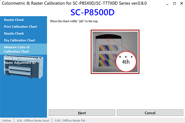 Check Point / チェックポイント
Align the marks (C) on the calibration chart (B) with those on the base plate (A).
- Click [Next].
- Referring to step 22, measure the lines from the 32th one to 38th.
- Once all the lines are measured, click [Next].
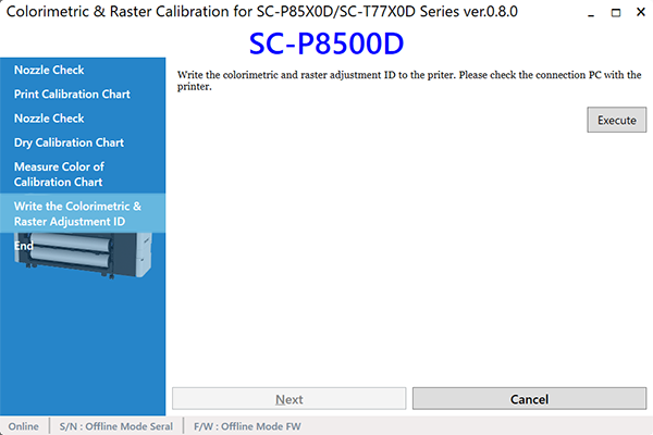
- Calculate the Colorimetric Adjustment ID from the measurement result, and save it into the printer. Confirm the printer is ready to print using the operation panel, and click [Execute].
- Click [Exit].
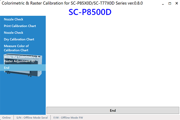
- Turn the printer OFF to finish the adjustment.