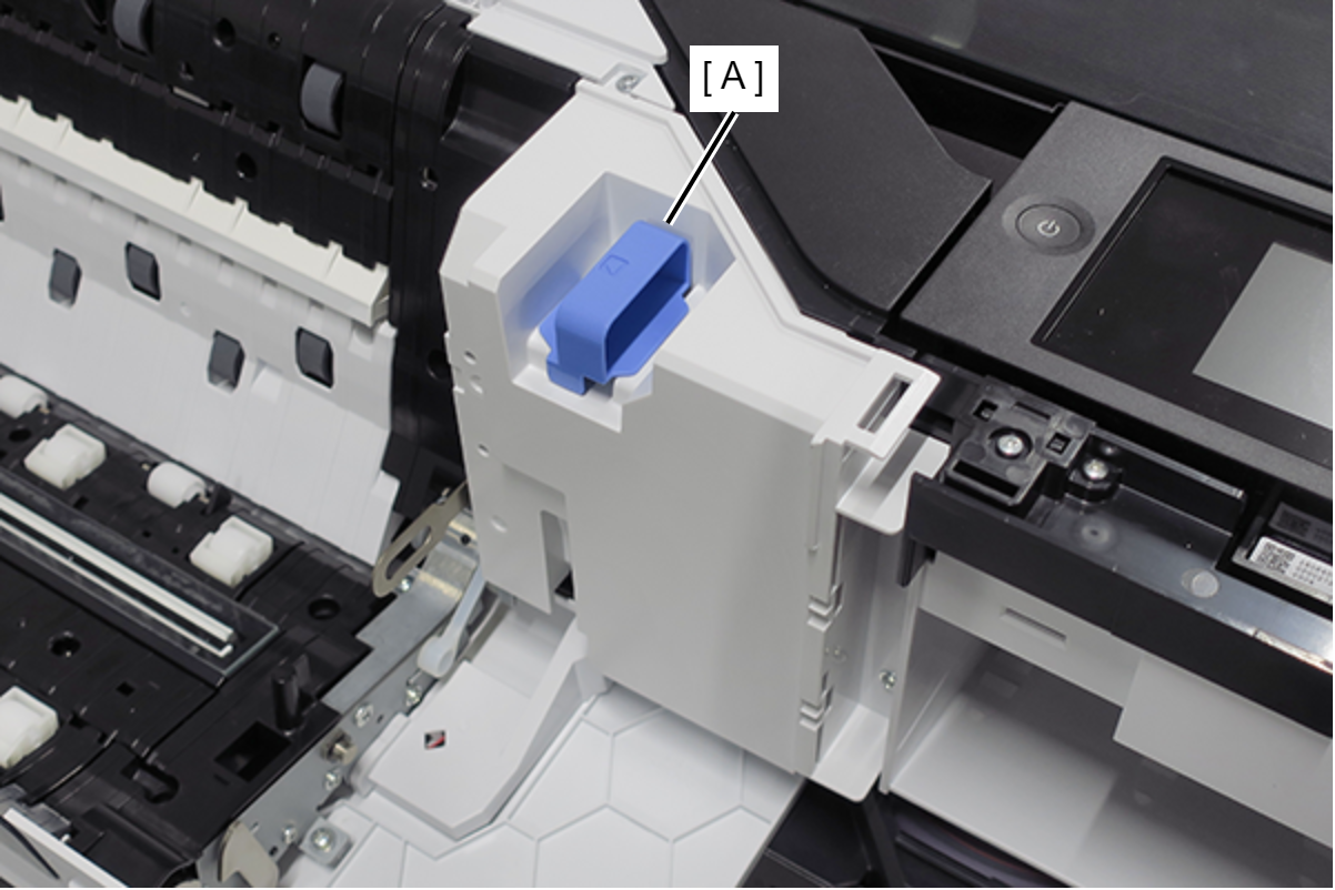
CIS Module Home Side Board
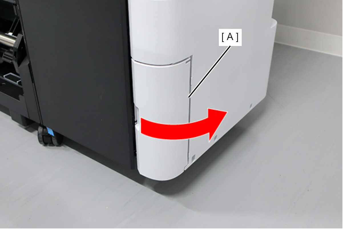
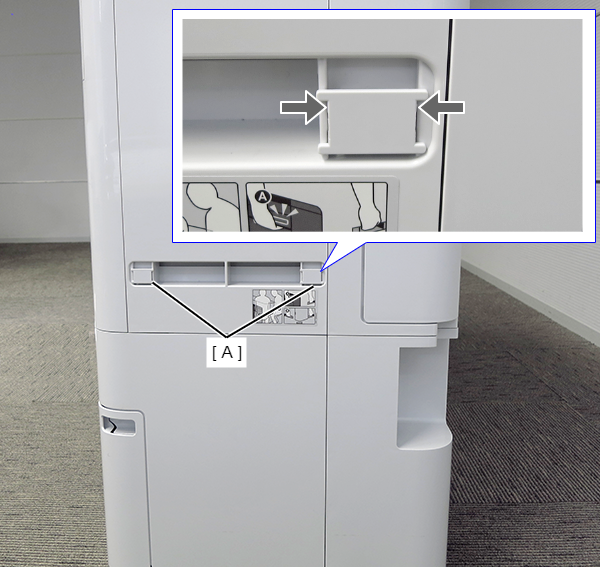
- Open the Maintenance Box Cover (A).
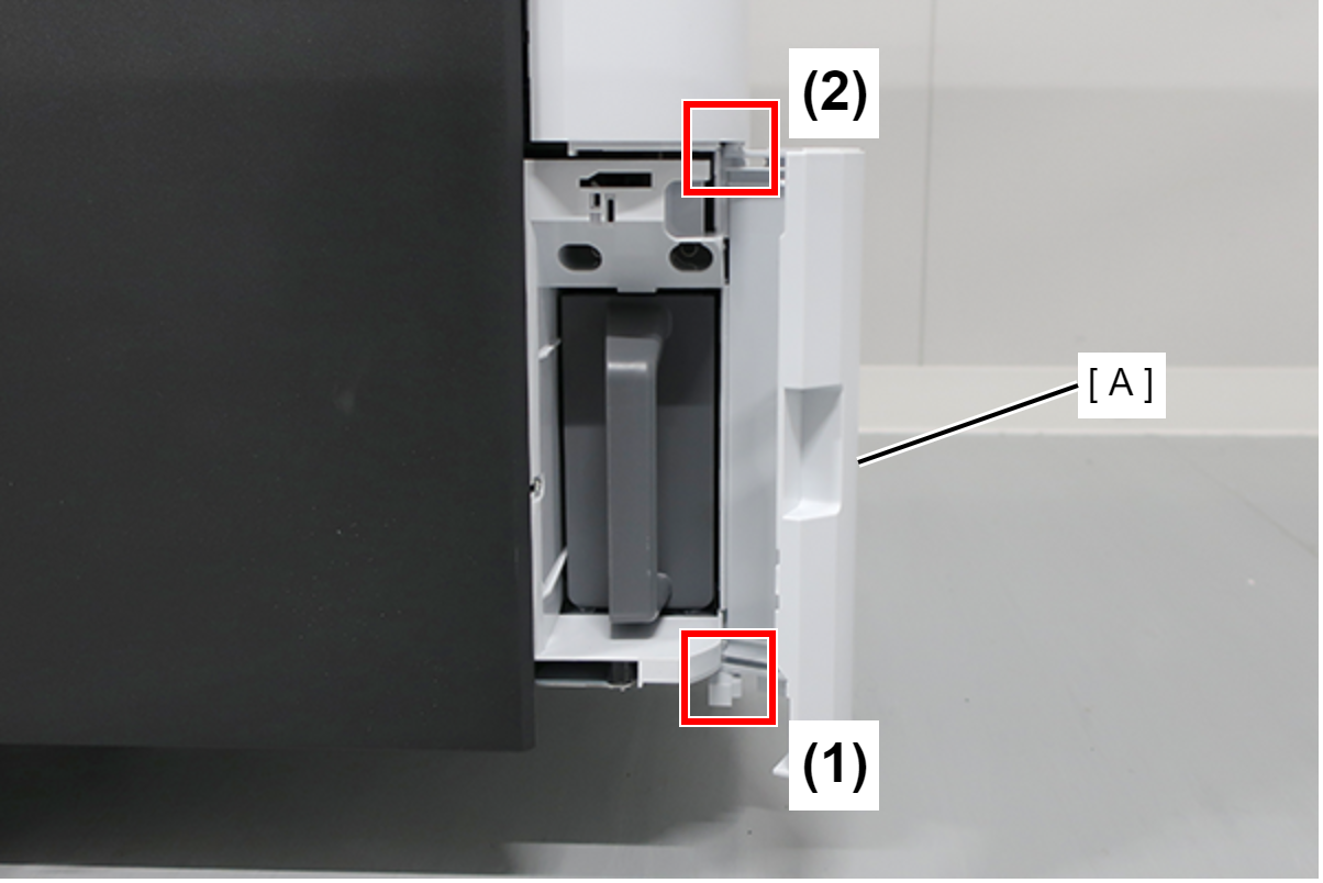
- Release the 2 tabs of the Maintenance Box Cover (A) in the order shown in the figure below, and remove.
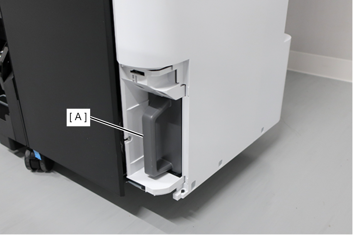
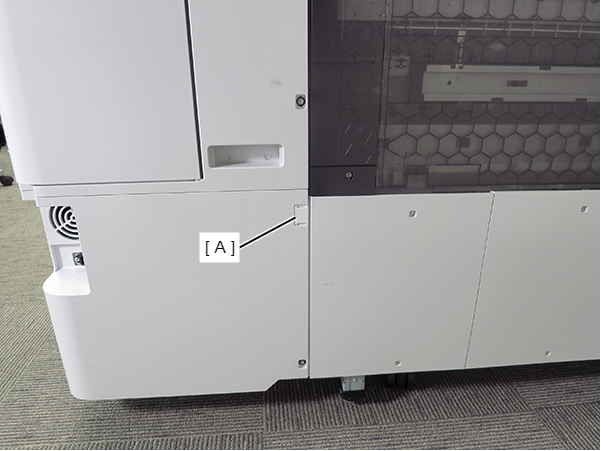
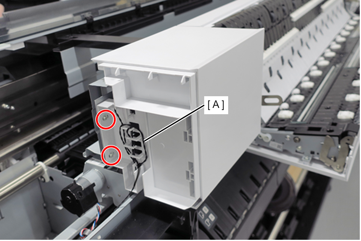
- Remove the Maintenance Box (A).
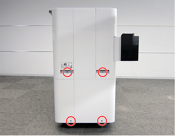
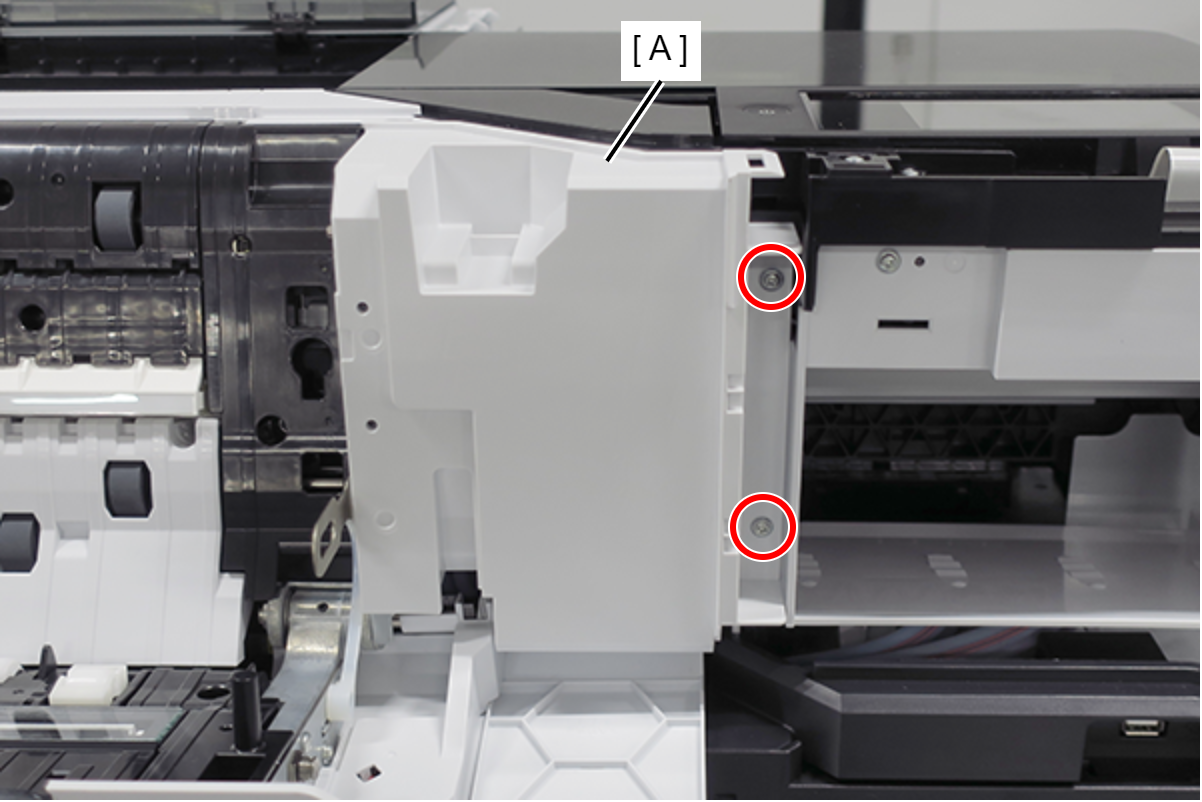
- Remove the screw.
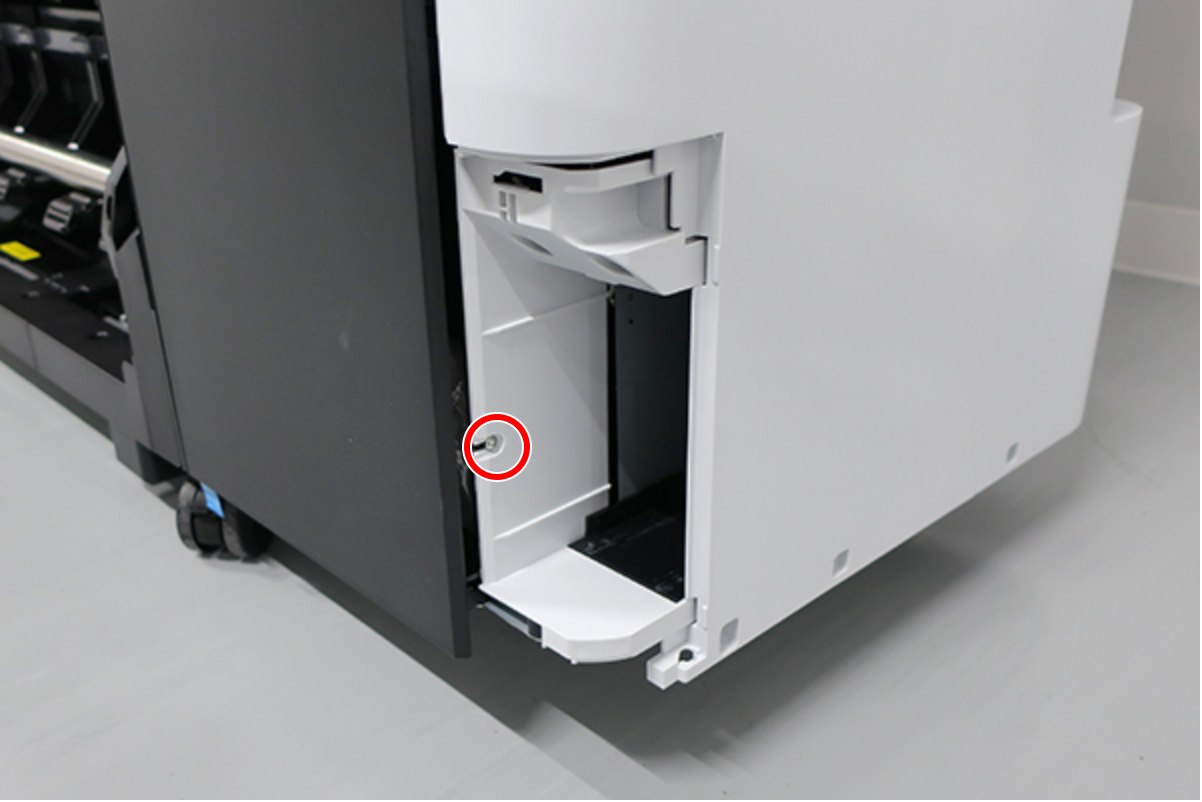
 : : Silver M3x8 Cup S-tite screw
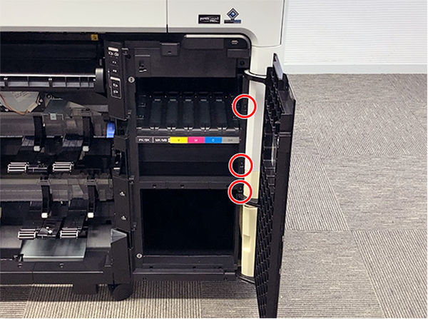
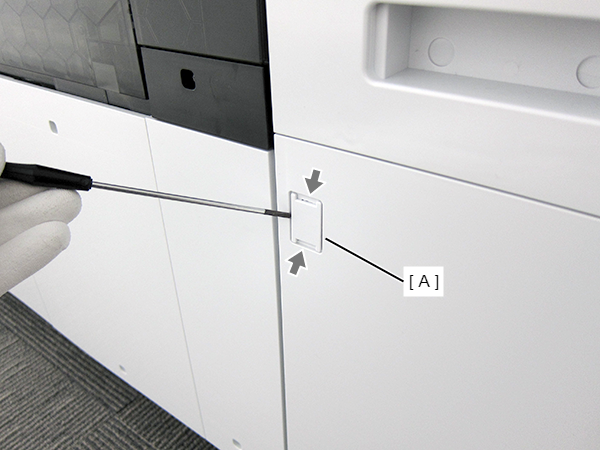
- Insert a flathead screwdriver and release the 2 hooks each, and remove the two screw cover (A).
- Insert a flathead screwdriver and release the 2 hooks, and remove the screw cover (A).
- Remove the three screws at the front side.
- : Black M3x8 Cup P-tite screw
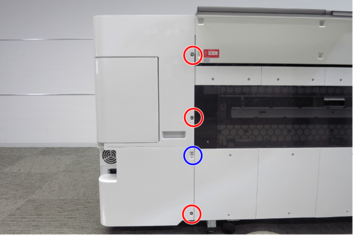
- Remove the five screws at the right side.
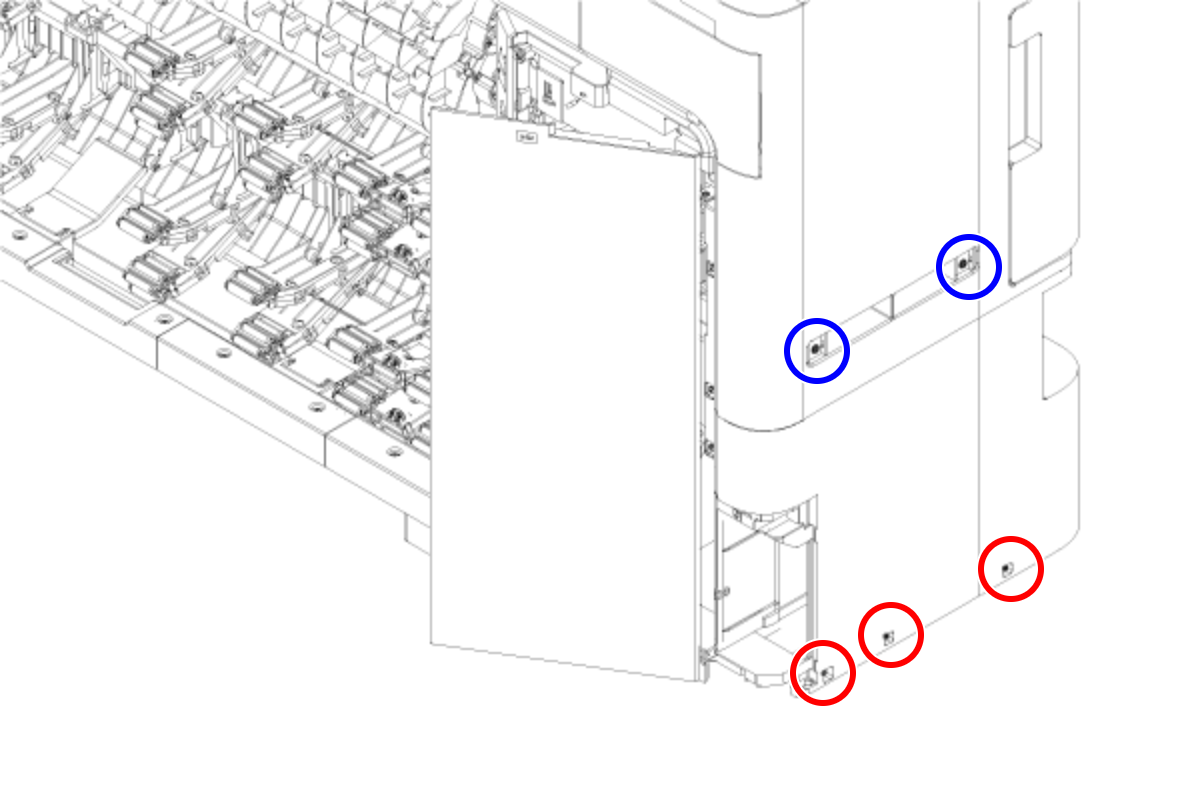
- : Silver M3x8 Cup S-tite screw
 : Silver/M4x8/machine screw
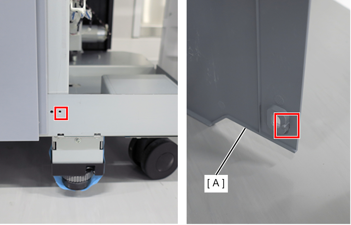
- Remove the four screws at the rear side.
- : Silver M3x8 Cup S-tite screw with plastic washer
- : : Silver M3x8 Cup S-tite screw
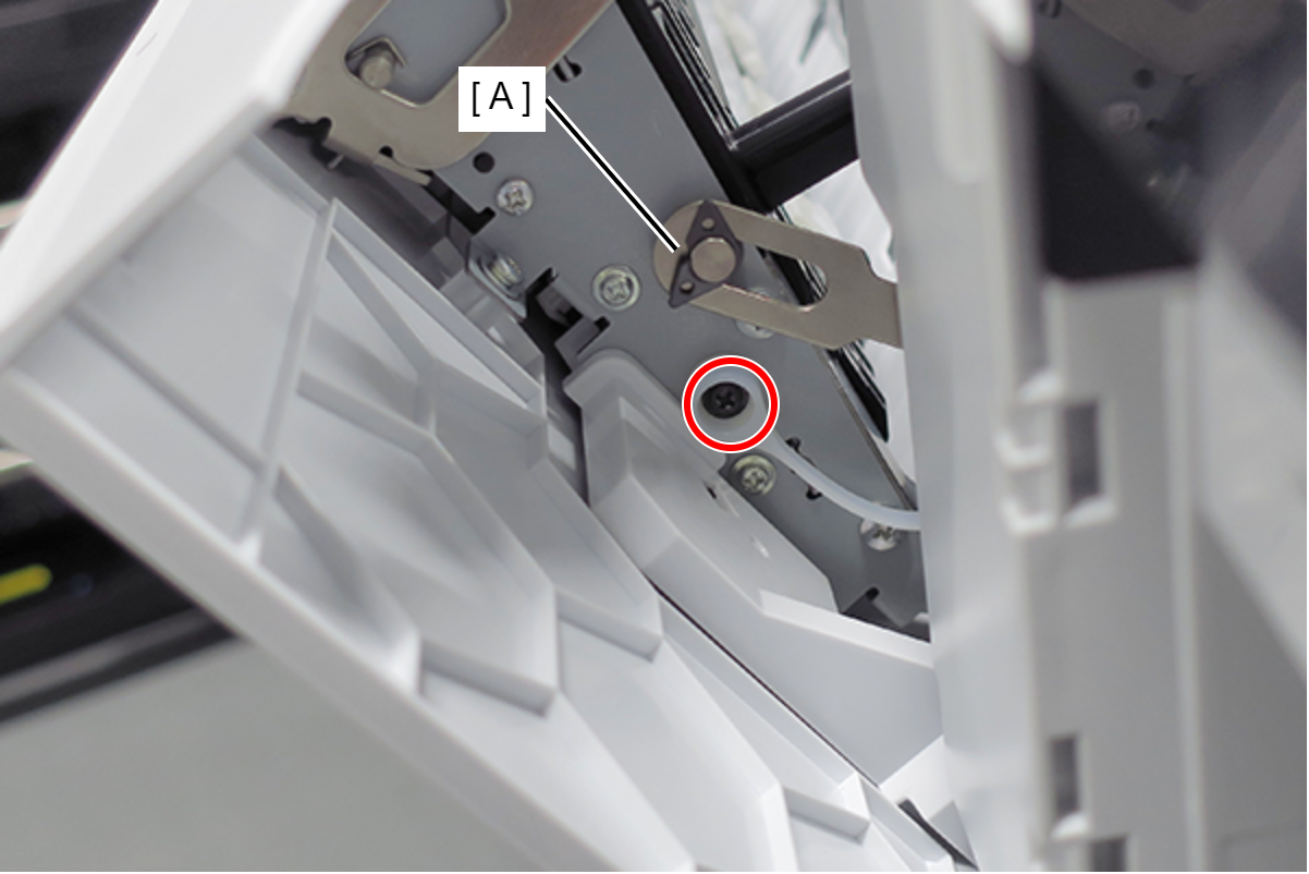
- On the printer rear side, release the dowel of the Home Side Cover Unit (A).
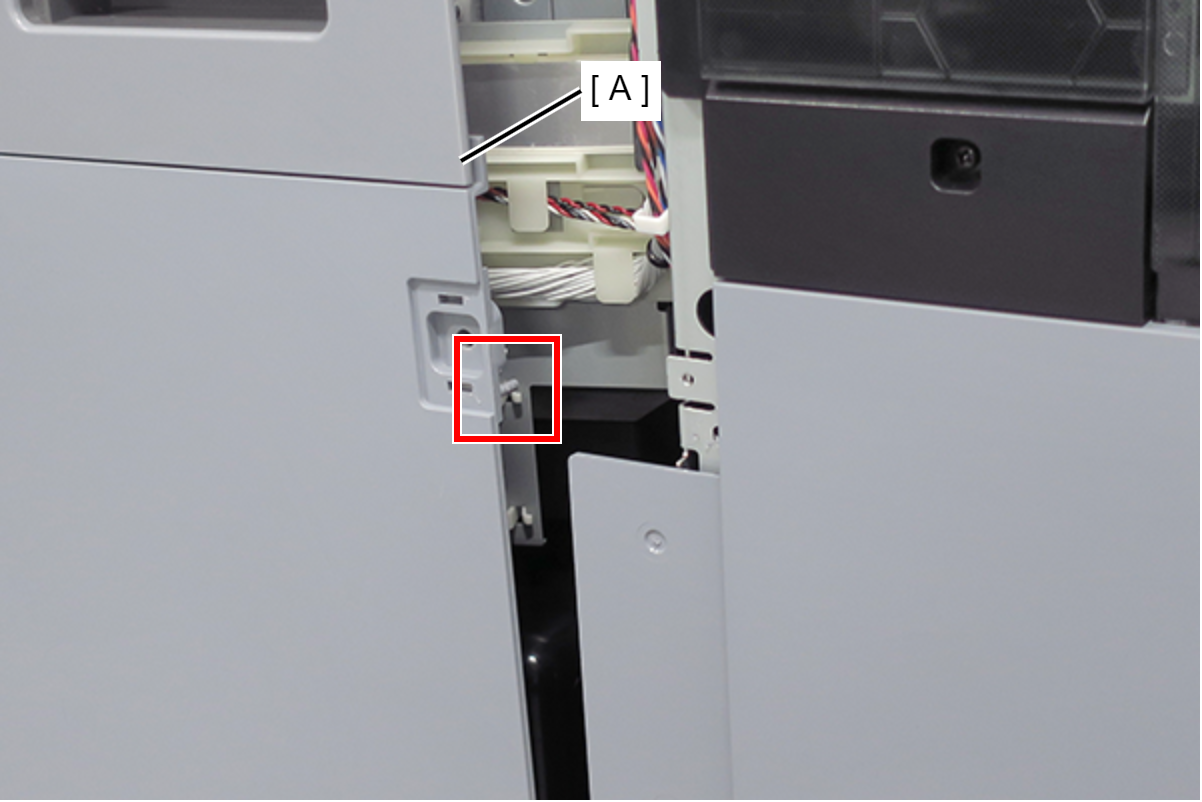
- Insert a flathead screwdriver and release the 2 tabs each, and remove the Home Side Cover Unit (A) in the direction of the arrow.
- Insert a flathead screwdriver and release the two hooks, and remove the screw cover (A).
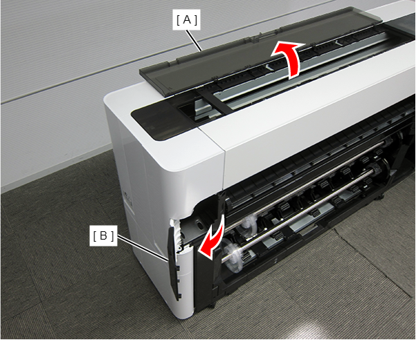
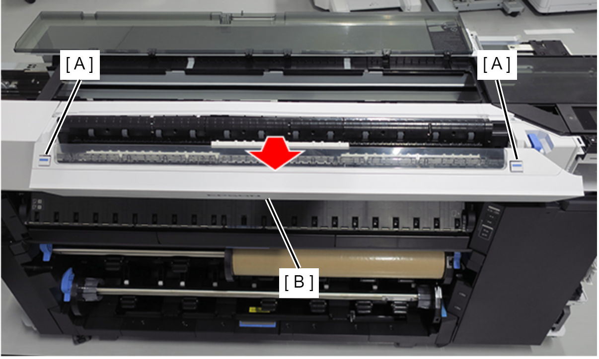
- Open the Printer Cover (A) and the Cutter Cover (B).
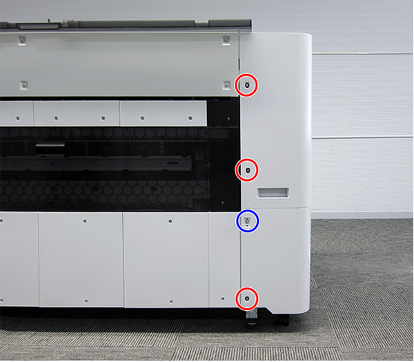
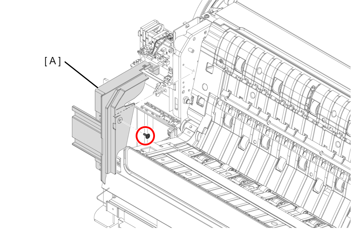
- Remove the three screws at the front side.
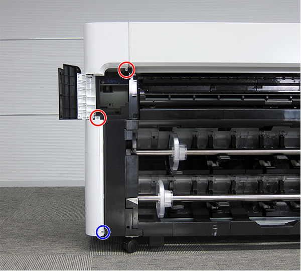
- : Silver M3x10 Cup P-tite screw
- : : Silver M3x8 Cup S-tite screw
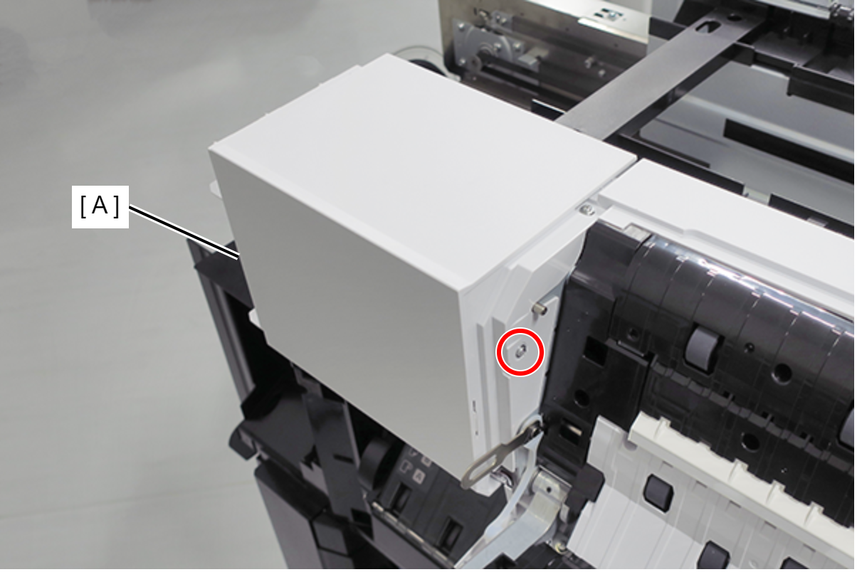
- Remove the screw at the top side.
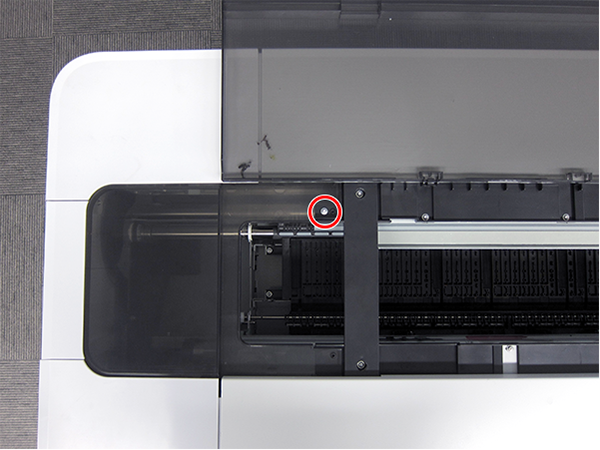
- : : Silver M3x8 Cup S-tite screw
- Remove the four screws at the rear side.
- : Silver M3x8 Cup S-tite screw with plastic washer
- : : Silver M3x8 Cup S-tite screw
- Remove the four screws at the left side.
- : Silver M3x8 Cup S-tite screw
- : Silver/M4x8/machine screw
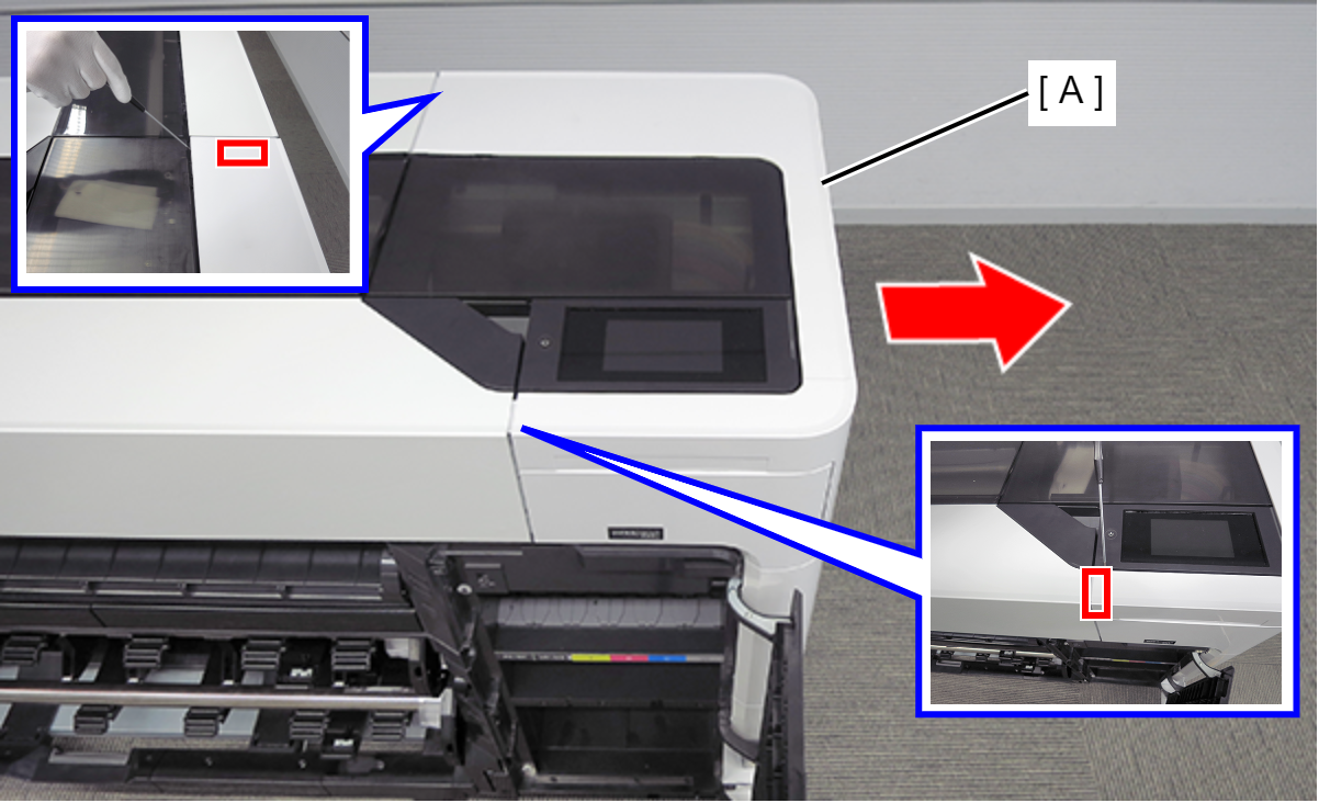
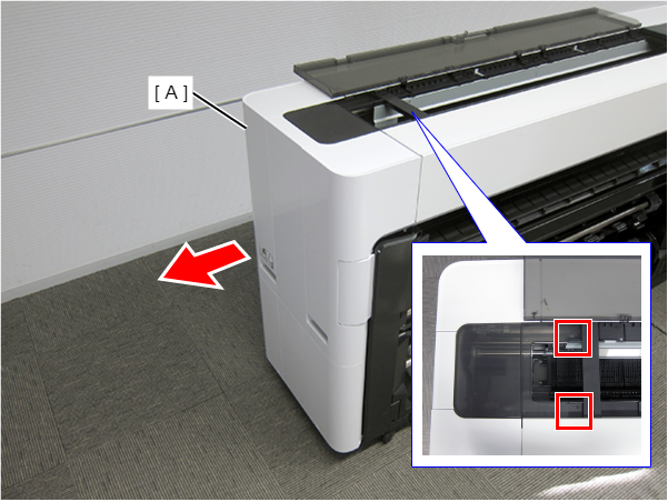
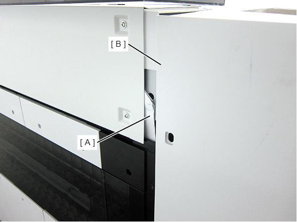
On the printer rear side, release the dowel of the Full Side Cover Unit (A).
Remove the Full Side Cover Unit (A) from the dowels, and remove it while it in the direction of the arrow.
 Assemble / 組み立て
When installing the Full Side Cover Unit (B), carefully the Head FFC (A) so that it does not damage.
- Remove the Button (A). (Only perform for SC-P8500DM series/SC-T7700DM series/SC-T5700DM series)
- Remove the two screws, and then remove the Scanner Home Side Cover (A). (Only perform for SC-P8500DM series/SC-T7700DM series/SC-T5700DM series)
- : Silver M3x8 Cup P-tite screw
- Push two buttons (A), and open the Scanner Unit (B). (Only perform for SC-P8500DM series/SC-T7700DM series/SC-T5700DM series)
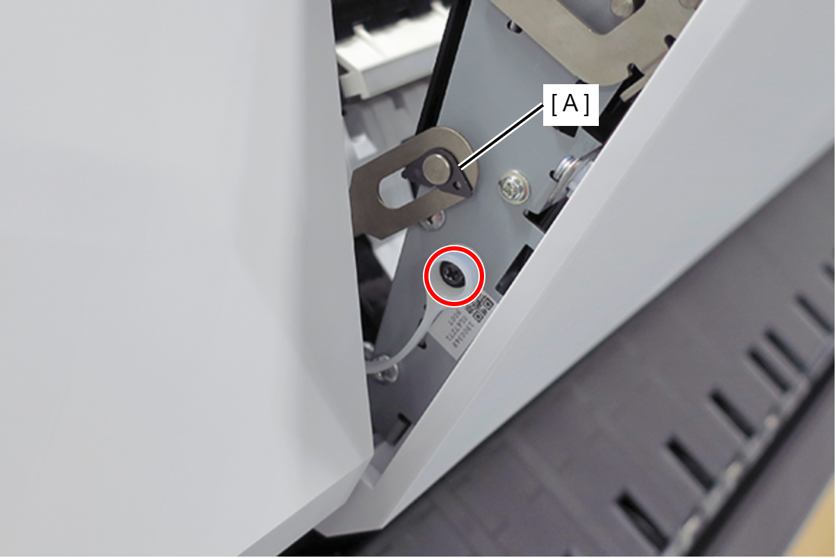
- Remove the screw on the printer home side. (Only perform for SC-P8500DM series/SC-T7700DM series/SC-T5700DM series)
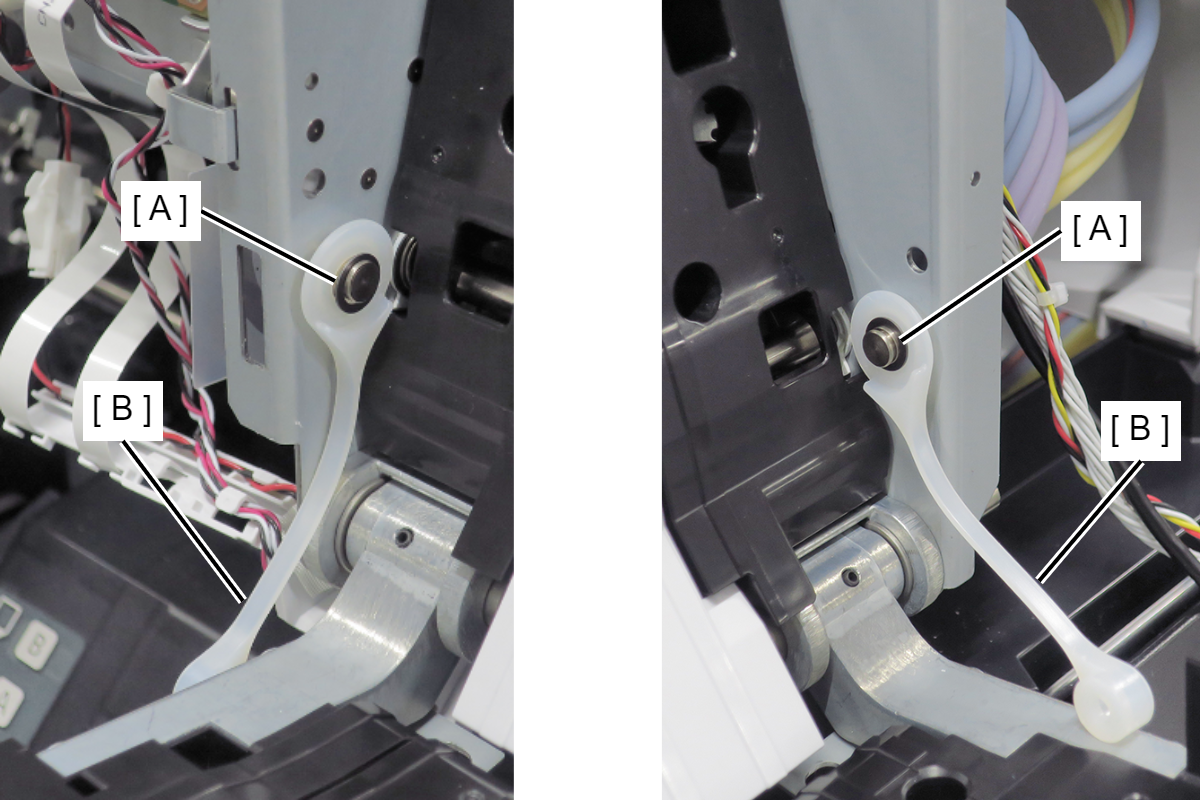
- Remove the C Shape Washer (A). (Only perform for SC-P8500DM series/SC-T7700DM series/SC-T5700DM series)
- : Black M3x4 Cup Step type S-tite screw
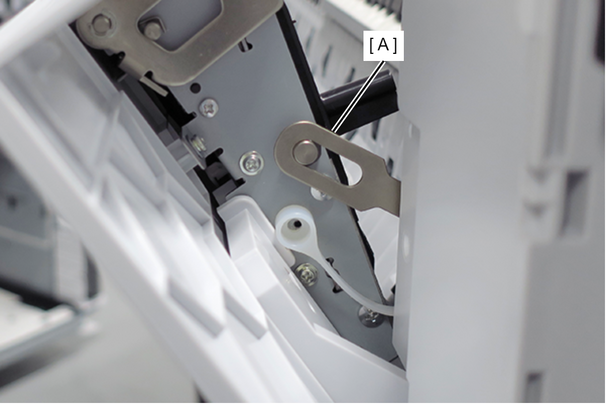
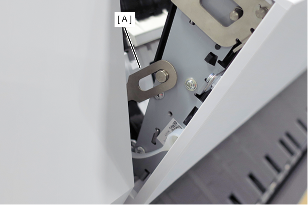
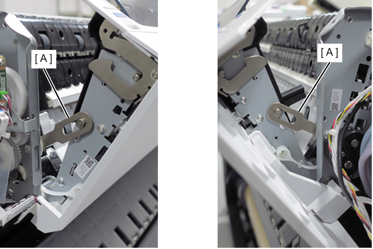
- Remove the Fixing Slider (A) from shaft. (Only perform for SC-P8500DM series/SC-T7700DM series/SC-T5700DM series)
- Remove the screw on the printer full side. (Only perform for SC-P8500DM series/SC-T7700DM series/SC-T5700DM series)
- Remove the C Shape Washer (A). (Only perform for SC-P8500DM series/SC-T7700DM series/SC-T5700DM series)
- : Black M3x4 Cup Step type S-tite screw
- Remove the Fixing Slider (A) from shaft. (Only perform for SC-P8500DM series/SC-T7700DM series/SC-T5700DM series)
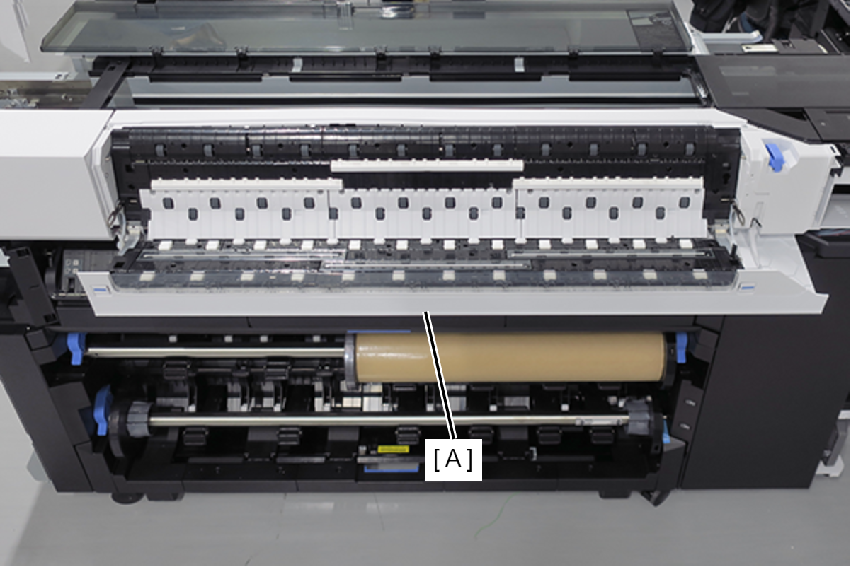
- Open the Scanner Unit (A). (Only perform for SC-P8500DM series/SC-T7700DM series/SC-T5700DM series)
- Release the sensor cable (A). (Only perform for SC-P8500DL series/SC-T7700DL series)
- Remove the two screws. (Only perform for SC-P8500DL series/SC-T7700DL series)
- : Silver M3x8 Cup S-tite screw
- Remove the screw, and then remove the Scanner Full Side Front Cover (A). (Only perform for SC-P8500DM series/SC-T7700DM series/SC-T5700DM series)
- : Silver M3x8 Cup S-tite screw
 Check Point / チェックポイント
- Scanner Full Side Front Cover of SC-T5700DM series
- Remove the C Shape Washer (A) and the Fixing Slider (B). (Only perform for SC-P8500DM series/SC-T7700DM series/SC-T5700DM series)
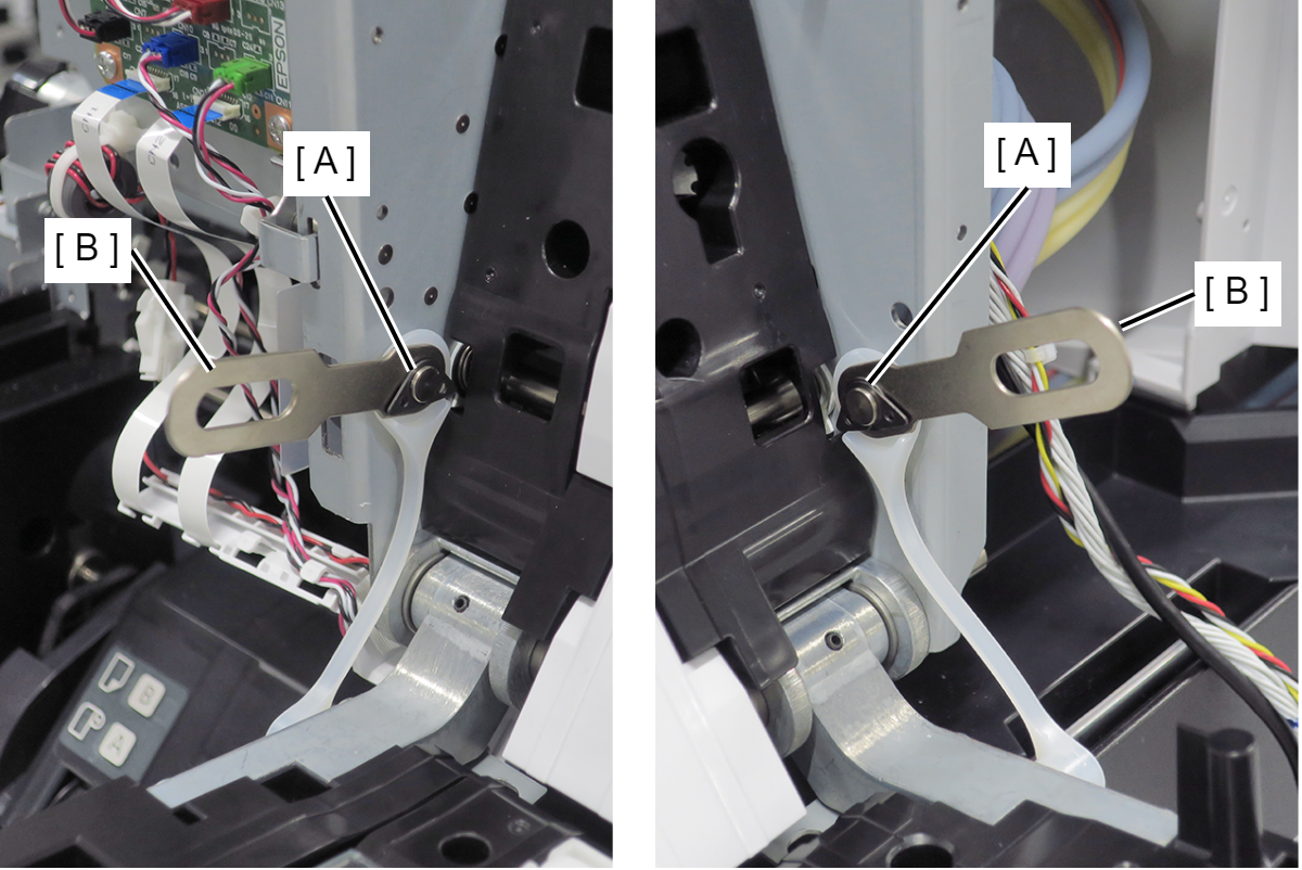
- Remove the Washer (A) and the Strap (B). (Only perform for SC-P8500DM series/SC-T7700DM series/SC-T5700DM series)
- Remove the four screws. (Only perform for SC-P8500DM series/SC-T7700DM series/SC-T5700DM series)
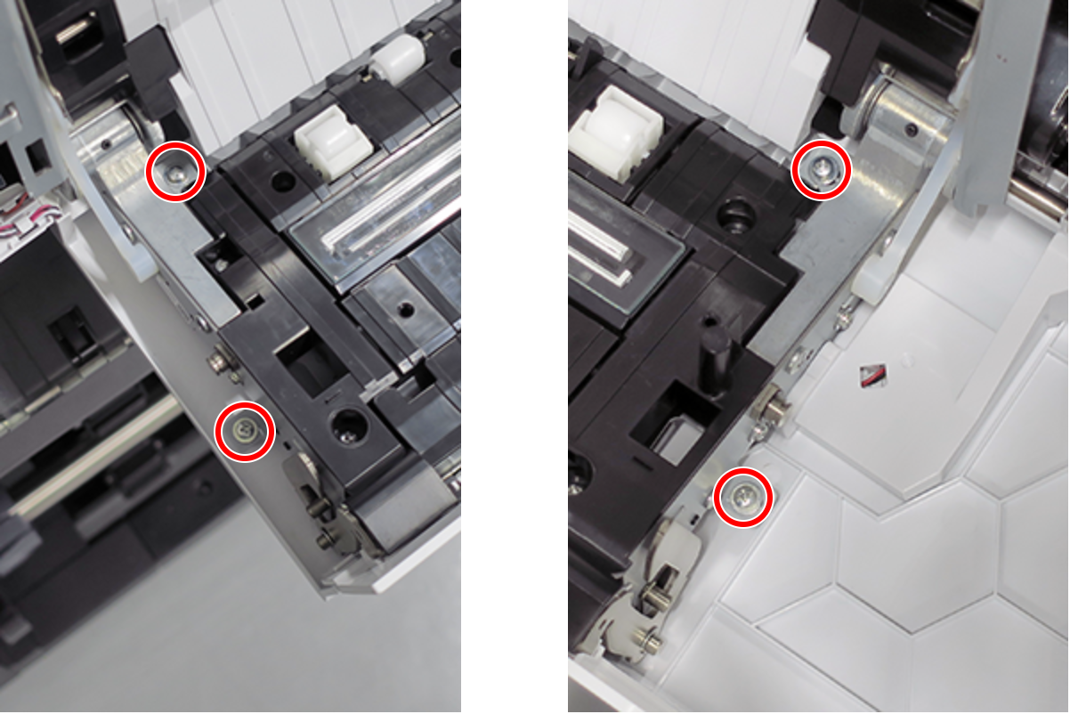
- :Silver M3x8 P-tite screw with built-in washer
- Hang each of the two fixing sliders (A) on the shaft. (Only perform for SC-P8500DM series/SC-T7700DM series/SC-T5700DM series)
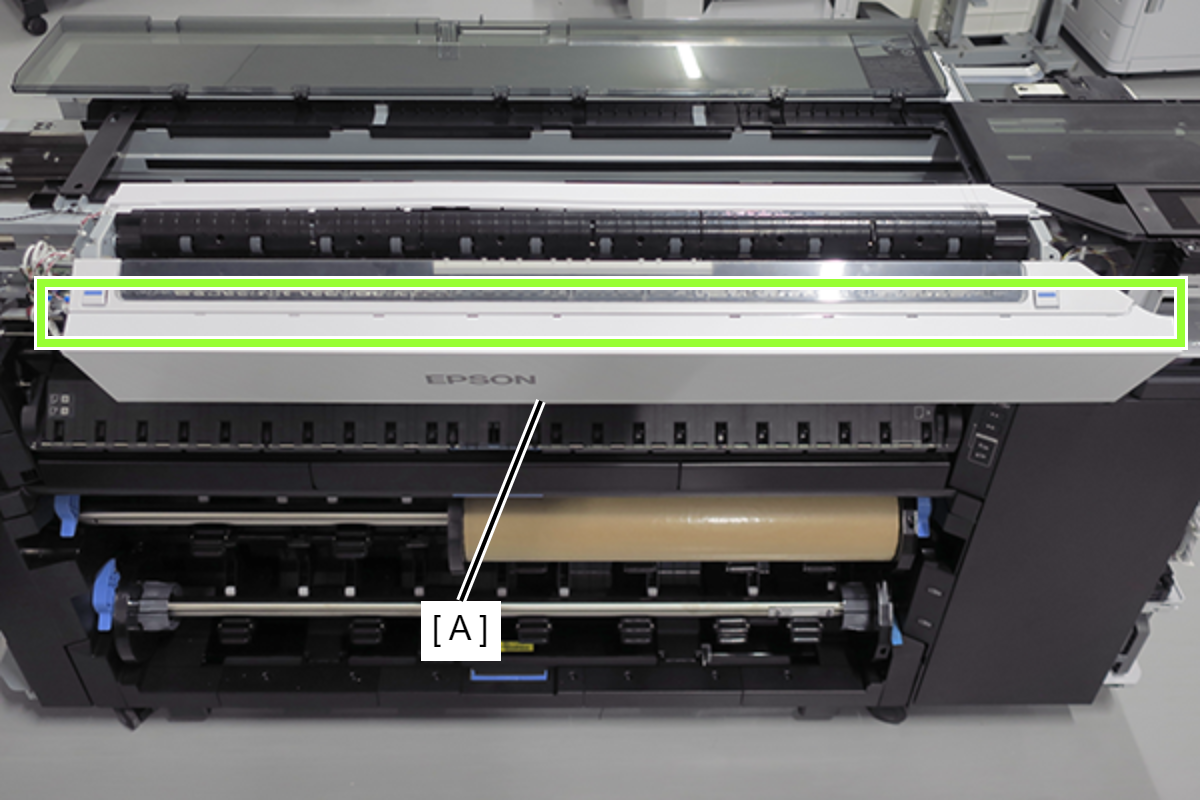
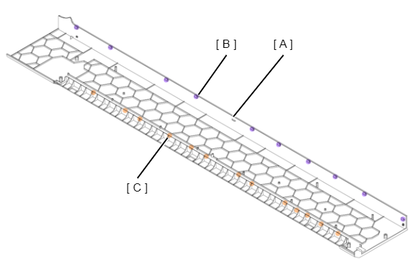
Release the 10 hooks and remove the Scanner Front Cover (A). (Only perform for SC-P8500DM series/SC-T7700DM series/SC-T5700DM series)
 Assembly / 組み立て
- Install the Scanner Front Cover (A) while engaging its 10 hooks (B) and 13 tabs (C) with the positioning points on the scanner.
- Install the Scanner Front Cover (A) while engaging its 10 hooks (B) and 13 tabs (C) with the positioning points on the scanner.
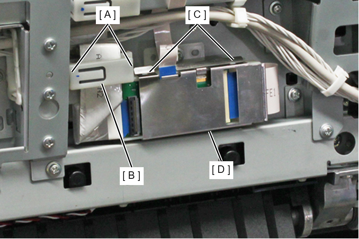
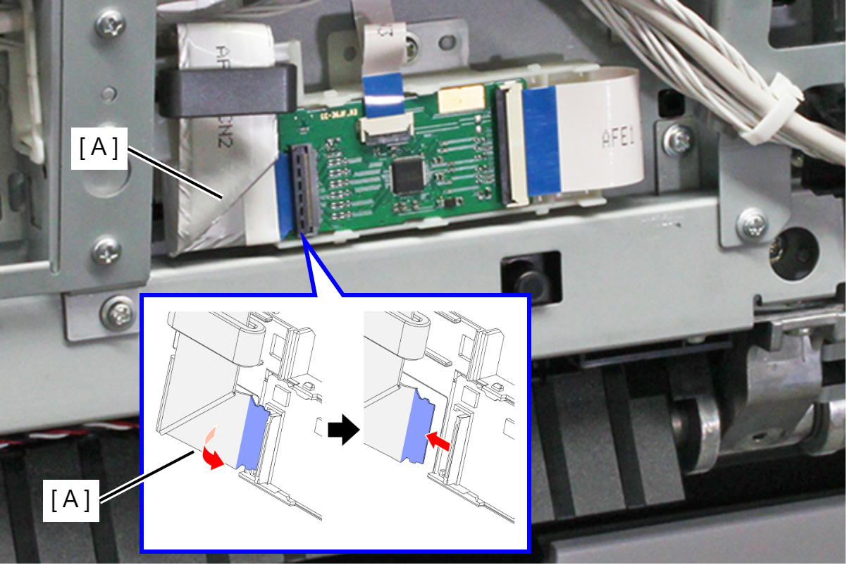
- Disengage the two hooks (A), and remove the ferrite core holder (B).
- Disengage the two hooks (C), and remove the shield plate (D).
- Lift and release the three FFC connector locks (A), and remove the screws.
- Disconnect the CIS Module Home Side FFC (B) and relay FFC (C) from the connectors on the CIS Module Home Side Board.
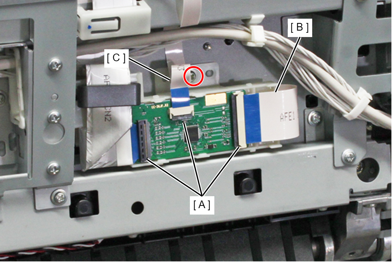
- : Silver M3x6 Cup S-tite screw
 Caution / 注意
- Because there is a risk of damage to the FFC terminal, when connecting/removing the CIS Module Home Side Board FFC to/from the connector, do not move the connector up or down.
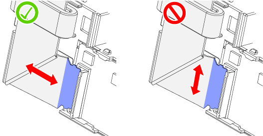
- The two protrusions on the CIS Module Home Side Board FFC (A) connector can easily break when removing the FFC, therefore care is required.
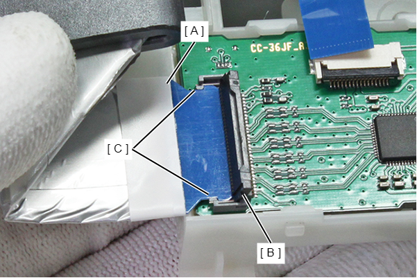
- Lift the CIS Module Home Side Board FFC (A) so that it rotates with its tip as a fulcrum, remove from the two connector protrusions, and pull the FFC straight out.
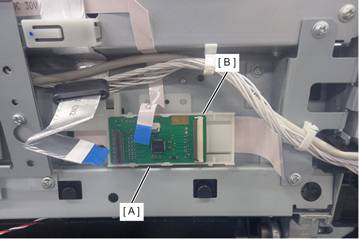
- Remove the CIS Module Home Side Board (A) and holder (B) together.
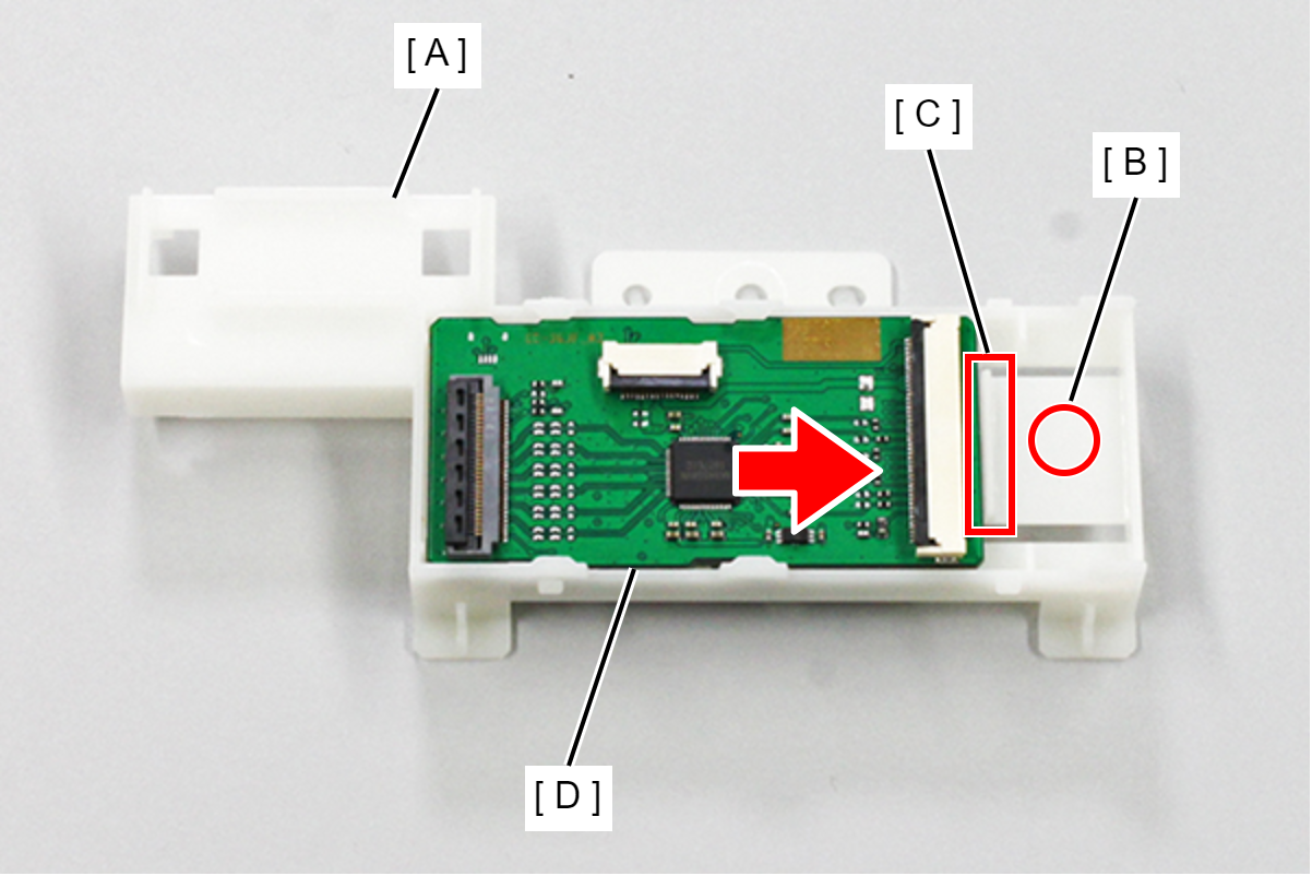
Push the CIS Module Home Side Holder (A) part A (B) and release the hook (C), then slide out the CIS Module Home Side Board (D) in the direction of the arrow to remove.
 Caution / 注意
- When replaced the CIS Module Home Side Board, make sure to replace the CIS Module Center Board and the CIS Module Full Side Board together.
- After replacing the CIS Module Home Side Board, make sure to perform firmware update.