CH83 Main-B Circuit Board Unit
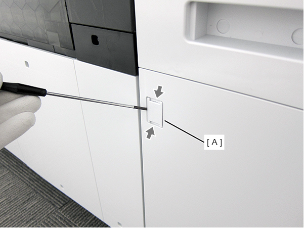
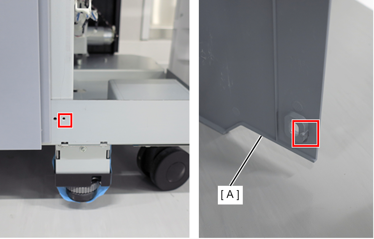
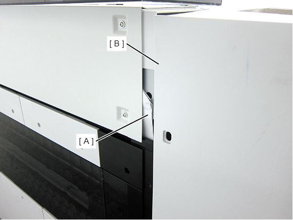
- Insert a flathead screwdriver and release the two hooks, and remove the screw cover (A).
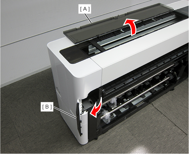
- Open the Printer Cover (A) and the Cutter Cover (B).
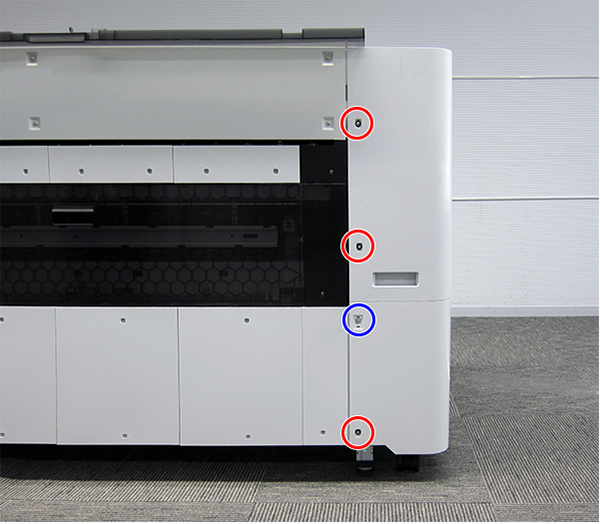
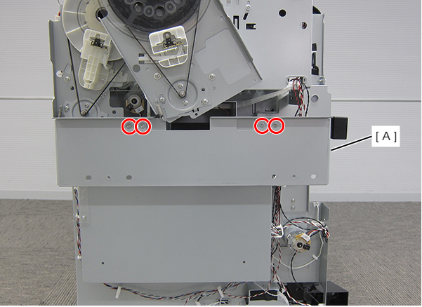
- Remove the three screws at the front side.
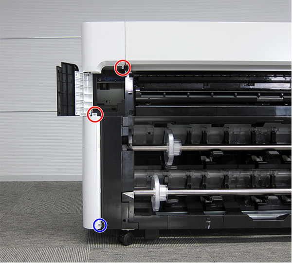
 : Silver M3x10 Cup P-tite screw
 : : Silver M3x8 Cup S-tite screw
- Remove the screw at the top side.
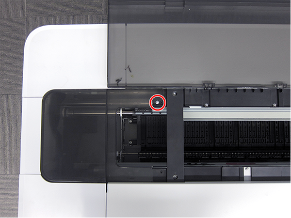
- : : Silver M3x8 Cup S-tite screw
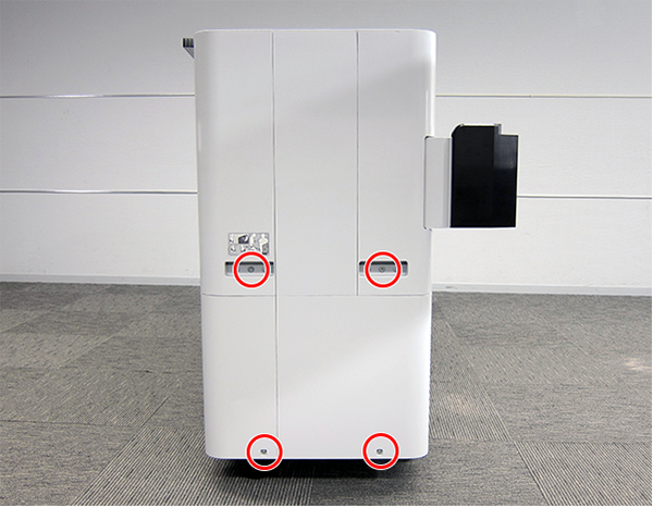
- Remove the four screws at the rear side.
- : Silver M3x8 Cup S-tite screw with plastic washer
- : : Silver M3x8 Cup S-tite screw
- Remove the four screws at the left side.
- : Silver M3x8 Cup S-tite screw
- : Silver/M4x8/machine screw
On the printer rear side, release the dowel of the Full Side Cover Unit (A).
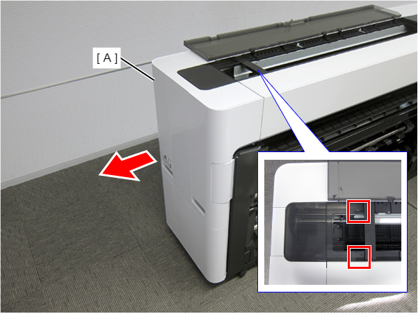
Remove the Full Side Cover Unit (A) from the dowels, and remove it while it in the direction of the arrow.
 Assemble / 組み立て
When installing the Full Side Cover Unit (B), carefully the Head FFC (A) so that it does not damage.
- Remove the four screws and then remove the Housing Support Plate.
- : Silver M3x8 Cup S-tite screw
- Remove the seven screws and then remove the CH83 Main-B Board Cover (A).
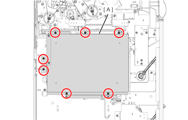
- : Silver M3x8 Cup S-tite screw
Assemble / 組み立てTake care that the cables do not get pinched.
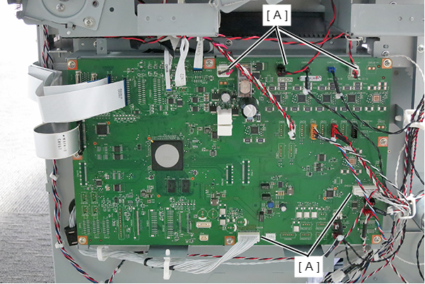
- Unlock the connectors (A) and then disconnect the two FFCs.
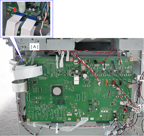
- Disengage the hooks, and disconnect the cables from the connectors (A) (CN408、CN500、CN503、CN506、CN522).
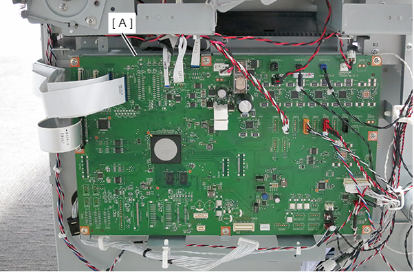
- Disconnect the remaining FFCs and cables that connected the CH83 Main-B Circuit Board (A).
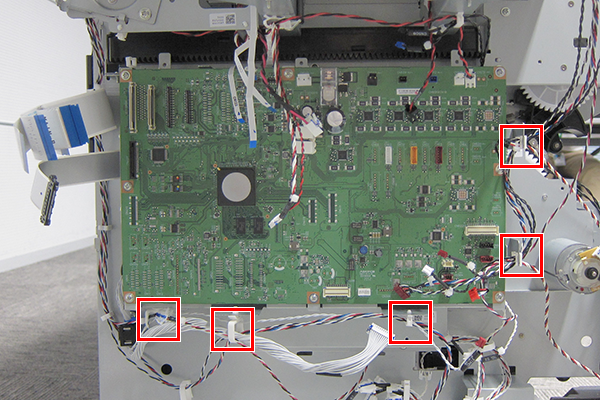
- Release cable from five clamps.
- Remove the seven screws, and remove the CH83 Main-B Circuit Board Unit (A).
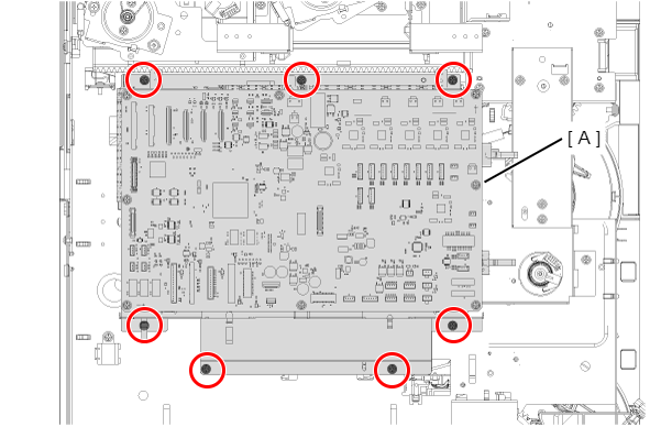
- : Silver M3x8 Cup S-tite screw
 Adjustment / 調整
Take care that the cables do not get pinched.