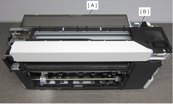
Front Paper Guide Middle
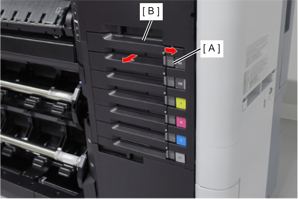
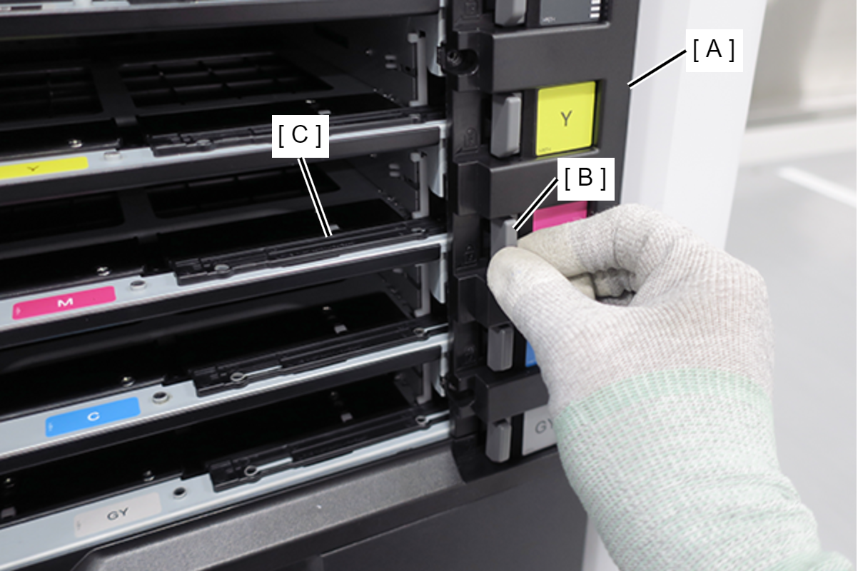
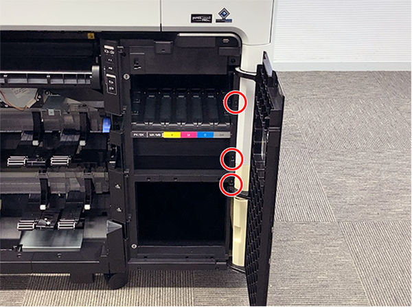
- Release the 6 locks (A), and remove the 6 Ink Pack Trays (B). (Only perform for SC-P8500DL series/SC-T7700DL series)
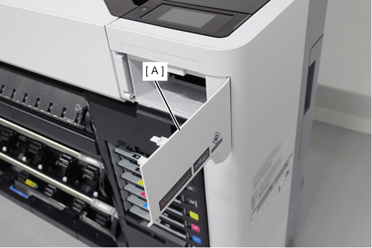
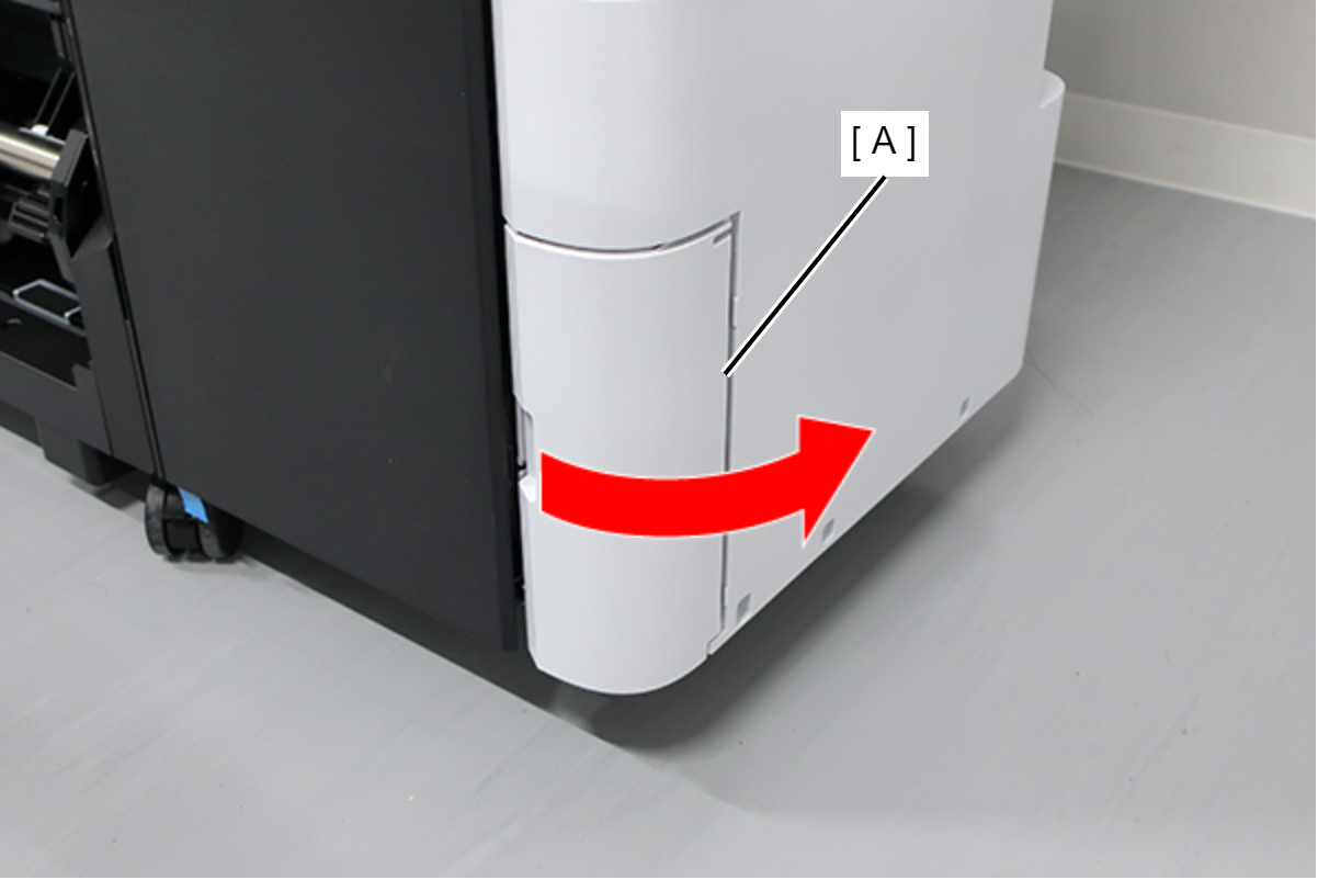
Open the Maintenance Cover (A). (Only perform for SC-P8500DL series/SC-T7700DL series)
- Remove the screw. (Only perform for SC-P8500DL series/SC-T7700DL series)
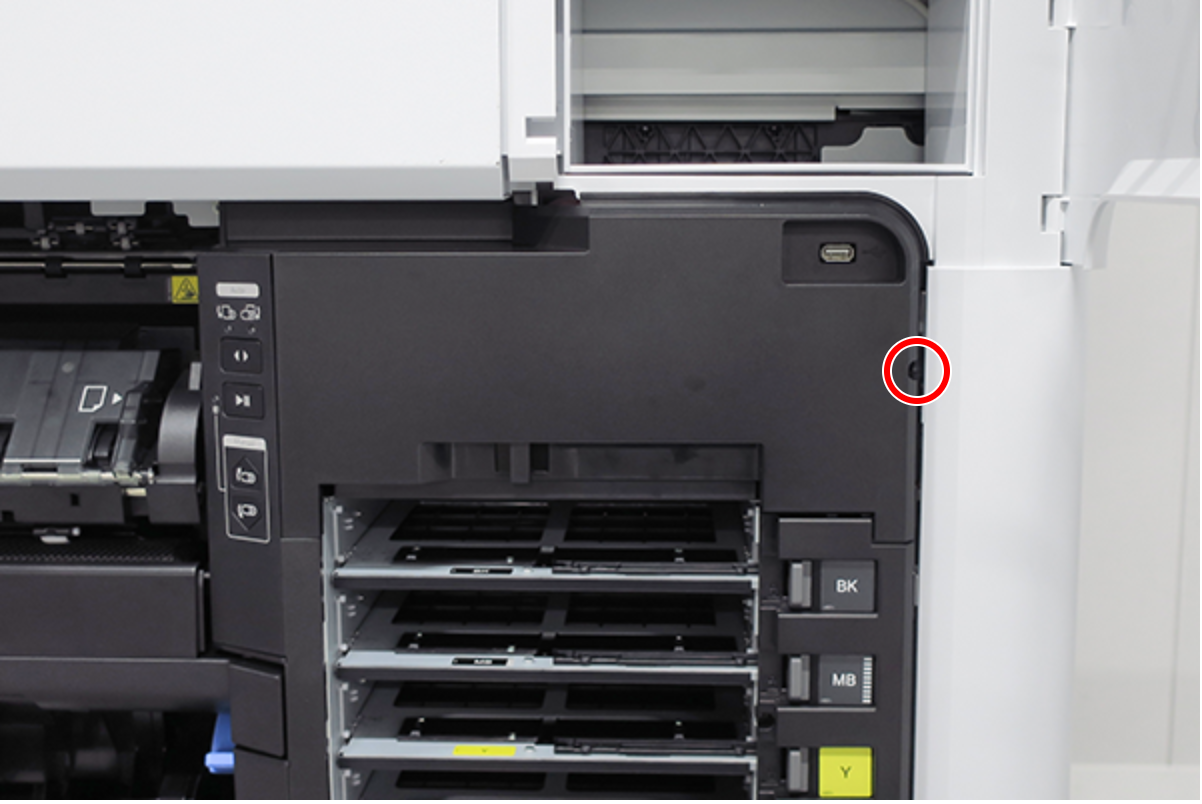
 :Black M3x8 S-tite screw
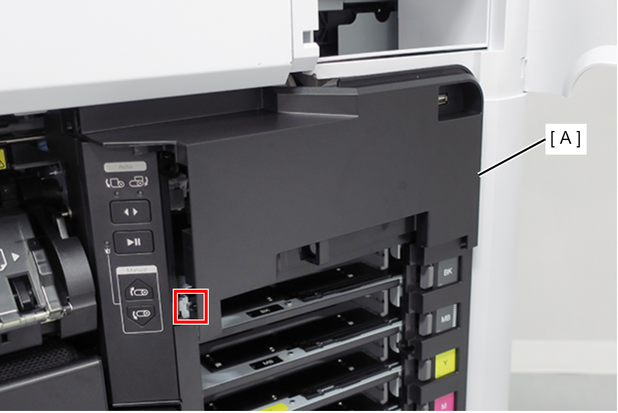
Release the hook, and remove the Ink Holder (RIPS) Upper Cover (A). (Only perform for SC-P8500DL series/SC-T7700DL series)
 Assembly / 組み立て
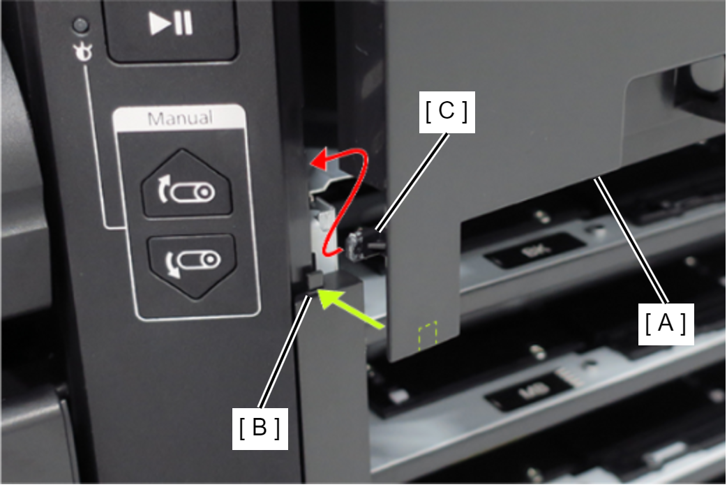
- Insert the Ink Holder (RIPS) Upper Cover (A) tab (B).
- Insert the Ink Holder (RIPS) Upper Cover (A) hook (C).
Remove the two screws, and remove the USB cable (A). (Only perform for SC-P8500DL series/SC-T7700DL series)
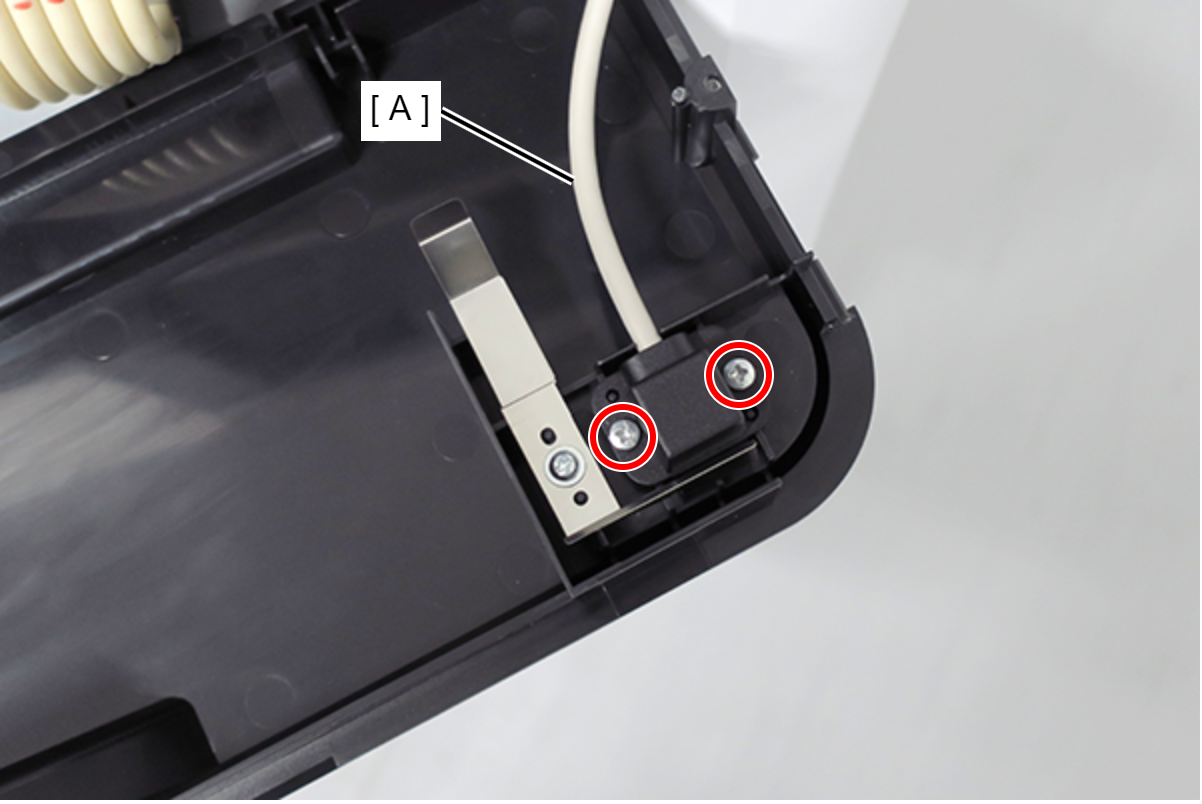
- : Silver M3x8 P-tite screw
Remove the two screws. (Only perform for SC-P8500DL series/SC-T7700DL series)
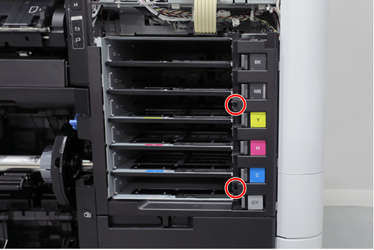
- : Silver M3x8 S-tite screw
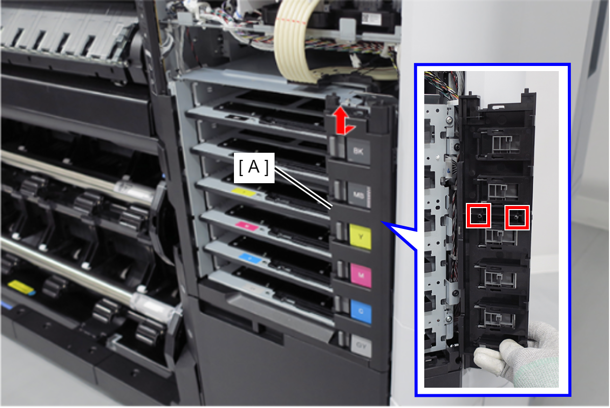
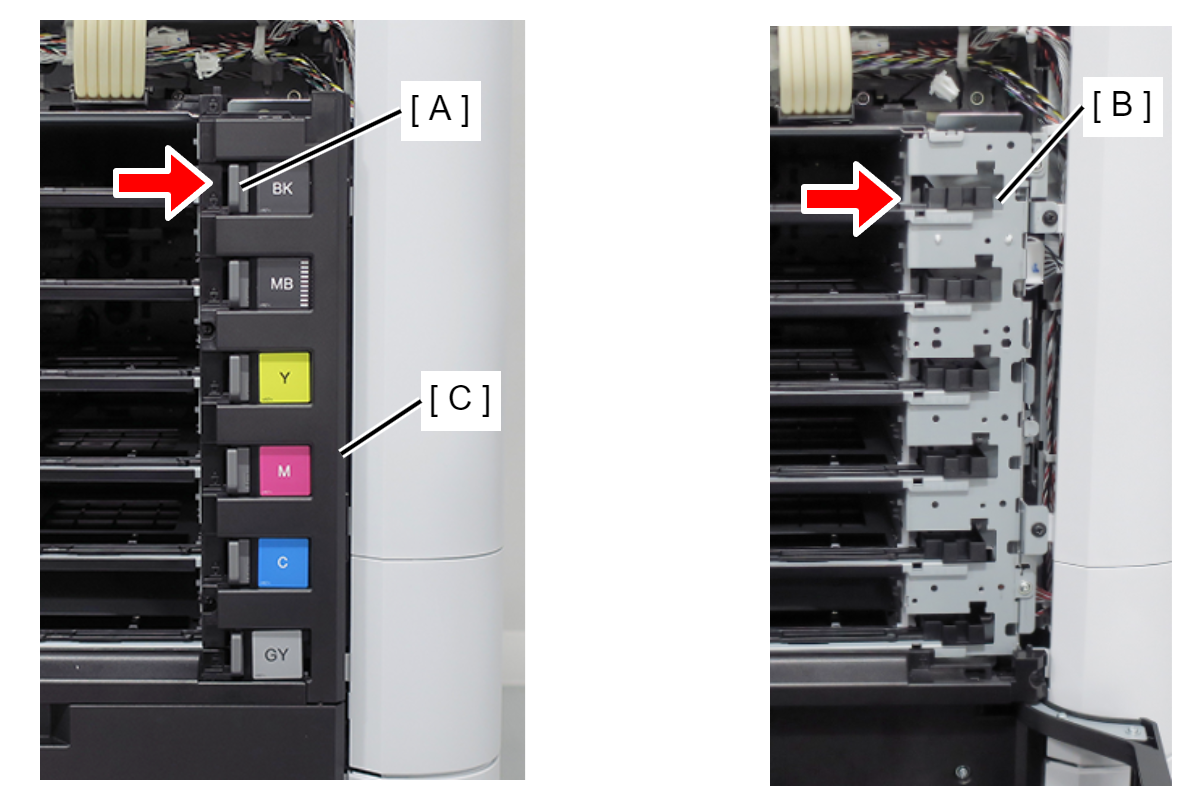
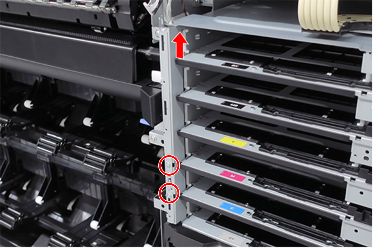
- Pull the Ink Pack Tray Right Side (A) slightly forward and release the 2 dowels. (Only perform for SC-P8500DL series/SC-T7700DL series)
Slide the Ink Pack Tray Right Side (A) upwards to remove. (Only perform for SC-P8500DL series/SC-T7700DL series)
 Assembly / 組み立て
- The gray lock lever (A) and ink plate (B) will come off when removing the Ink Pack Tray Right Side (C). Install them after installing the Ink Pack Tray Right Side (C) in the main unit.
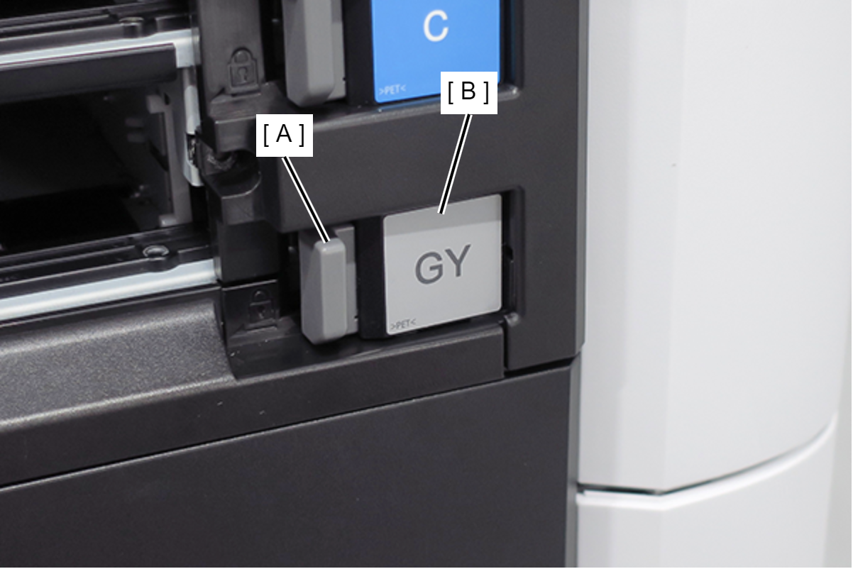
- With the lock lever (A) and tray lever (B) moved to the right side, install the Ink Pack Tray Right Side (C).
- After installing the Ink Pack Tray Right Side (A), move the lock lever (B) and confirm that the tray lever (C) moves in conjunction.
- The gray lock lever (A) and ink plate (B) will come off when removing the Ink Pack Tray Right Side (C). Install them after installing the Ink Pack Tray Right Side (C) in the main unit.
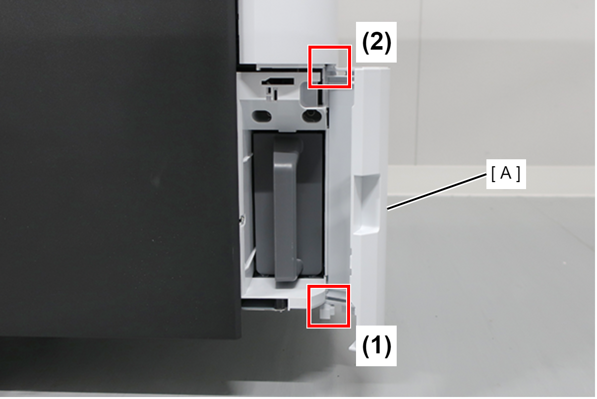
- Open the Maintenance Box Cover (A).
- Release the 2 tabs of the Maintenance Box Cover (A) in the order shown in the figure below, and remove.
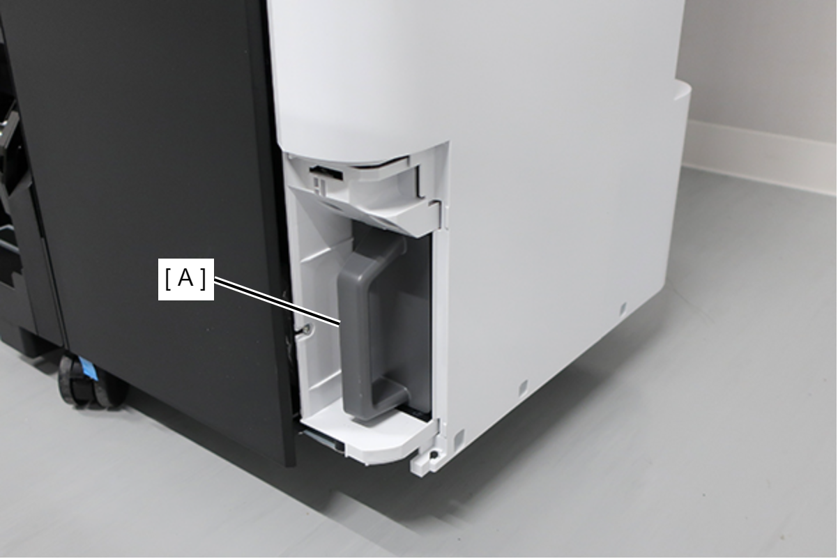
- Remove the Maintenance Box (A).
- Remove the screw.
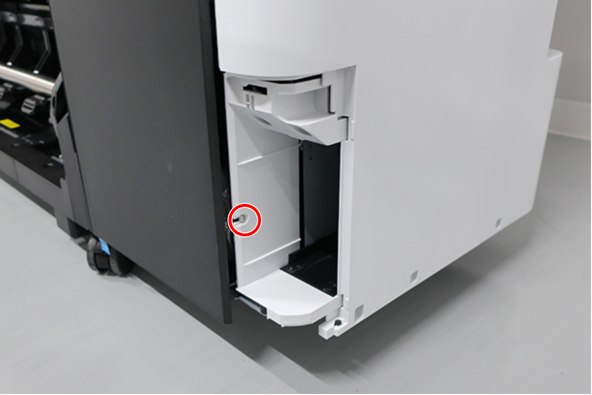
- : : Silver M3x8 Cup S-tite screw
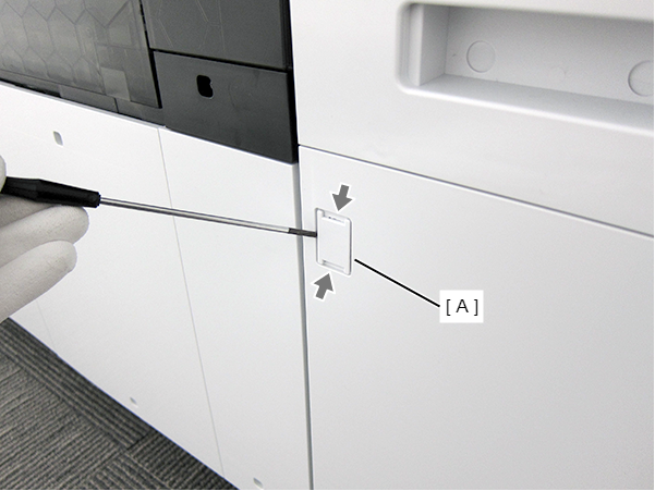
- Insert a flathead screwdriver and release the 2 hooks each, and remove the two screw cover (A).
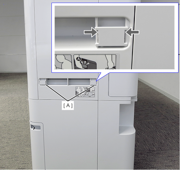
- Insert a flathead screwdriver and release the 2 hooks, and remove the screw cover (A).
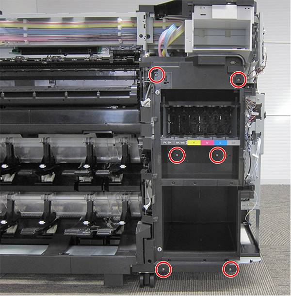
- Remove the three screws at the front side.
- : Black M3x8 Cup P-tite screw
- Remove the five screws at the right side.
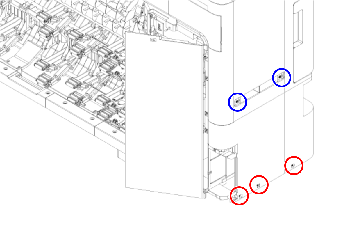
- : Silver M3x8 Cup S-tite screw
 : Silver/M4x8/machine screw
- Remove the four screws at the rear side.
- : Silver M3x8 Cup S-tite screw with plastic washer
- : : Silver M3x8 Cup S-tite screw
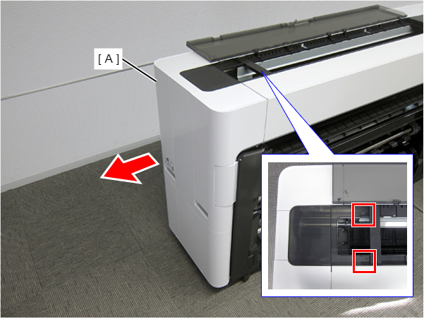
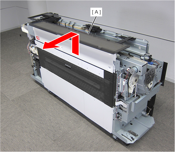
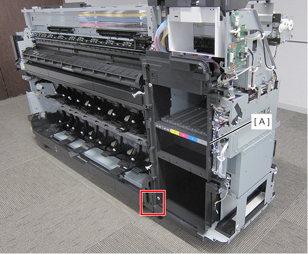
- On the printer rear side, release the dowel of the Home Side Cover Unit (A).
- Insert a flathead screwdriver and release the 2 tabs each, and remove the Home Side Cover Unit (A) in the direction of the arrow.
- Insert a flathead screwdriver and release the two hooks, and remove the screw cover (A).
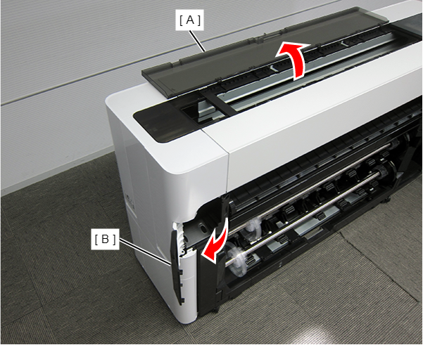
- Open the Printer Cover (A) and the Cutter Cover (B).
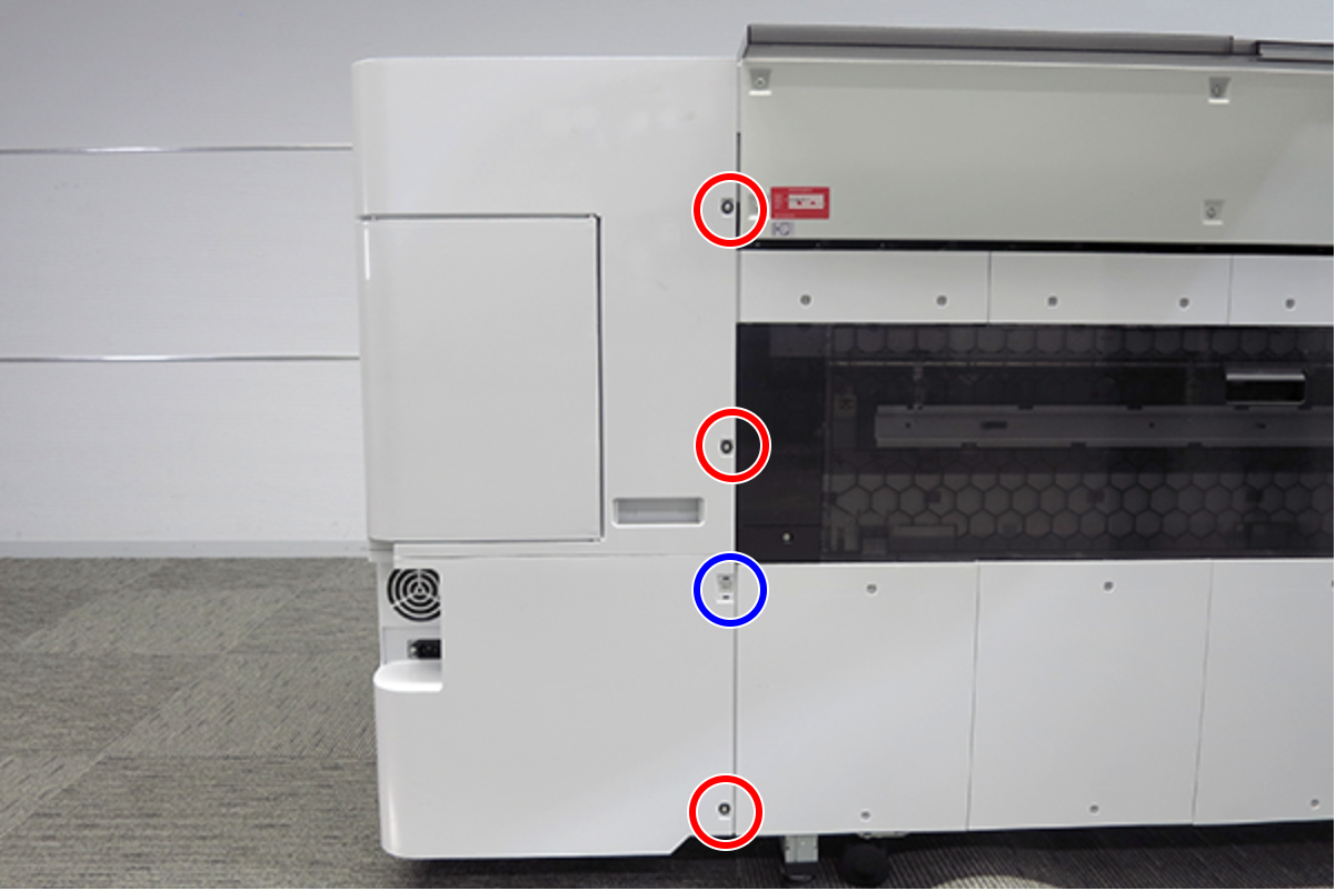
- Remove the three screws at the front side.
- : Silver M3x10 Cup P-tite screw
- : : Silver M3x8 Cup S-tite screw
- Remove the screw at the top side.
- : : Silver M3x8 Cup S-tite screw
- Remove the four screws at the rear side.
- : Silver M3x8 Cup S-tite screw with plastic washer
- : : Silver M3x8 Cup S-tite screw
- Remove the four screws at the left side.
- : Silver M3x8 Cup S-tite screw
- : Silver/M4x8/machine screw
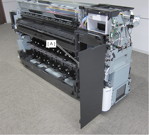
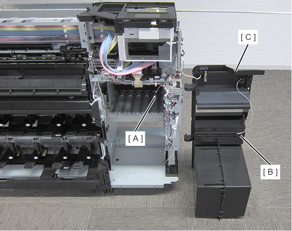
On the printer rear side, release the dowel of the Full Side Cover Unit (A).
Remove the Full Side Cover Unit (A) from the dowels, and remove it while it in the direction of the arrow.
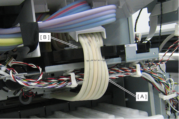
 Assemble / 組み立て
When installing the Full Side Cover Unit (B), carefully the Head FFC (A) so that it does not damage.
- Release the sensor cable (A). (Only perform for SC-P8500D series/SC-T7700D series/SC-T5700D series/SC-P6500D series/SC-P6500DE series/SC-T3700D series/SC-T3700DE series/SC-P6500E series/SC-T3700E series/SC-P8500DL series/SC-T7700DL series)
- Open the Printer Cover (A). (Only perform for SC-P8500D series/SC-T7700D series/SC-T5700D series/SC-P6500D series/SC-P6500DE series/SC-T3700D series/SC-T3700DE series/SC-P6500E series/SC-T3700E series/SC-P8500DL series/SC-T7700DL series)
Remove the Home Side Top Cover (B). (Only perform for SC-P8500D series/SC-T7700D series/SC-T5700D series/SC-P6500D series/SC-P6500DE series/SC-T3700D series/SC-T3700DE series/SC-P6500E series/SC-T3700E series/SC-P8500DL series/SC-T7700DL series)
Remove the four screws at the front side. (Only perform for SC-P8500D series/SC-T7700D series/SC-T5700D series/SC-P6500D series/SC-P6500DE series/SC-T3700D series/SC-T3700DE series/SC-P6500E series/SC-T3700E series/SC-P8500DL series/SC-T7700DL series)
- (Right):Silver M3x8 Cup S-tite screw
- (Left):SC-P8500D series/SC-T7700D series/SC-P8500DL series/SC-T7700DL series: Silver M3x8 Cup S-tite screw, SC-T5700D series/SC-P6500D series/SC-P6500DE series/SC-T3700D series/SC-T3700DE series/SC-P6500E series/SC-T3700E series: Silver M4x6 Shoulder Screw
 : Silver M3x10 Cup P-tite screw
Assemble / 組み立てTighten the right green screw with the grounding cable. (SC-P8500D series/SC-T7700D series/SC-P8500DL series/SC-T7700DL series only)
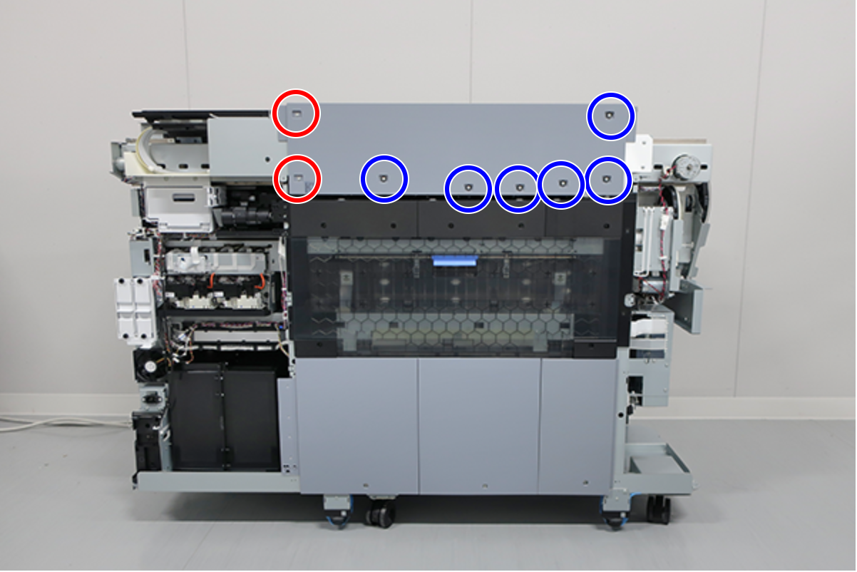
- Remove the screws on the top. (Only perform for SC-P8500D series/SC-T7700D series/SC-T5700D series/SC-P6500D series/SC-P6500DE series/SC-T3700D series/SC-T3700DE series/SC-P6500E series/SC-T3700E series/SC-P8500DL series/SC-T7700DL series)
SC-P8500D series/SC-T7700D series/SC-P8500DL series/SC-T7700DL series: 6 pcs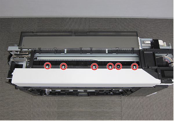
- : Black M3x8 Cup S-tite screw
- : Black M3x8 Cup S-tite screw
- : Black M3x8 Cup S-tite screw
- Remove the Front Top Cover (A) frontward. (Only perform for SC-P8500D series/SC-T7700D series/SC-T5700D series/SC-P6500D series/SC-P6500DE series/SC-T3700D series/SC-T3700DE series/SC-P6500E series/SC-T3700E series/SC-P8500DL series/SC-T7700DL series)
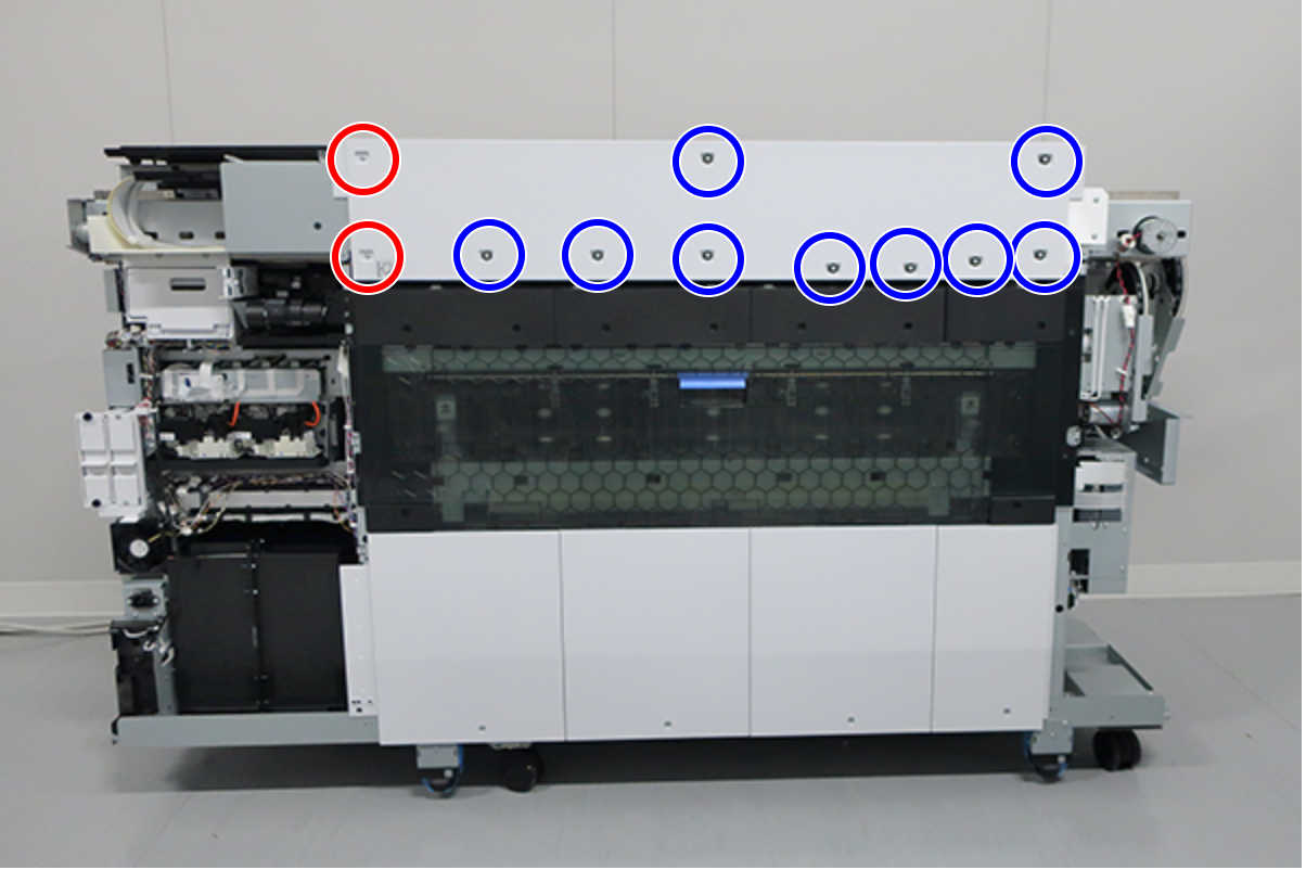
- Remove the screws on the top.
SC-P8500D series/SC-T7700D series/SC-P8500DL series/SC-T7700DL series/SC-P8500DM series/SC-T7700DM series: 8 pcs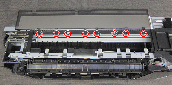
- : Silver M3x8 Cup S-tite screw
- : Silver M3x8 Cup S-tite screw
- : Silver M3x8 Cup S-tite screw
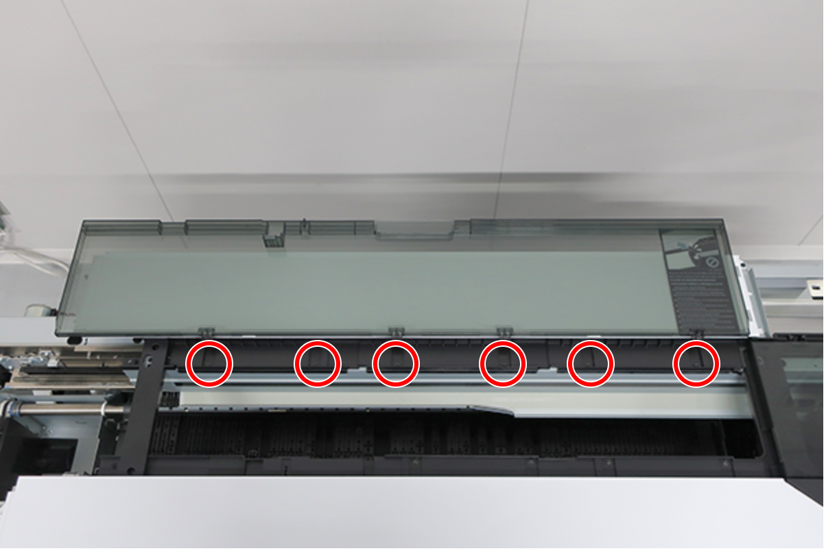
- Remove the screws on the back.
SC-P8500D series/SC-T7700D series/SC-P8500DL series/SC-T7700DL series/SC-P8500DM series/SC-T7700DM series: 6 pcs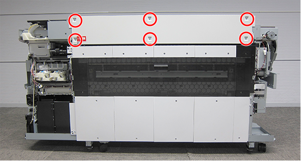
- : Silver M3x8 Cup S-tite screw
- : Silver M3x8 Cup S-tite screw
- : Silver M3x8 Cup S-tite screw with plastic washer
- : Silver M3x8 Cup S-tite screw
 : Silver M3x8 Cup S-tite screw with plastic washer
- Remove the Printer Cover Unit backward.
- Open the IH Cover Unit (A). (Only perform for SC-P8500DL series/SC-T7700DL series)
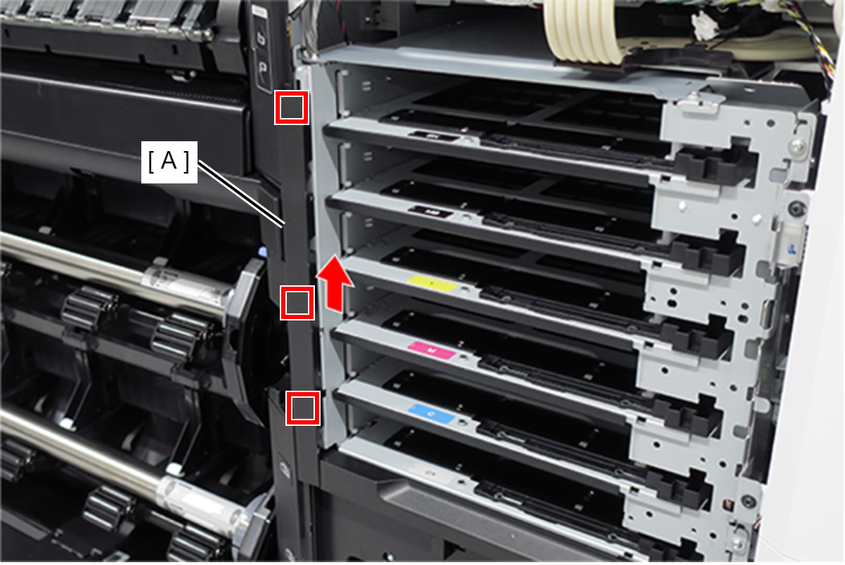
- Slide the Ink Pack Tray Left Side (A) upwards and release the 3 hooks to remove. (Only perform for SC-P8500DL series/SC-T7700DL series)
- Open the Ink Cartridge Cover (A). (Only perform for SC-P8500D series/SC-T7700D series/SC-T5700D series/SC-P6500D series/SC-P6500DE series/SC-T3700D series/SC-T3700DE series/SC-P6500E series/SC-T3700E series/SC-P8500DM series/SC-T7700DM series/SC-T5700DM series)
- Remove the two screws.
- Release the 2 hooks and then remove the Take-up Button Board Cover (A).
- : Black M3x10 Cup P-tite screw (SC-P8500D series/SC-T7700D series/SC-T5700D series/SC-P6500D series/SC-P6500DE series/SC-T3700D series/SC-T3700DE series/SC-P6500E series/SC-T3700E series/SC-P8500DM series/SC-T7700DM series/SC-T5700DM series only)
- : Black M3x10 Cup P-tite screw (SC-P8500D series/SC-T7700D series/SC-T5700D series/SC-P6500D series/SC-P6500DE series/SC-T3700D series/SC-T3700DE series/SC-P6500E series/SC-T3700E series/SC-P8500DM series/SC-T7700DM series/SC-T5700DM series)
- :Black M3x6 Cup S-tite screw (SC-P8500DL series/SC-T7700DL series)
- Remove the cable (A) from the connector.
- Open the Ink Cartridge Cover (A). (Only perform for SC-P8500D series/SC-T7700D series/SC-T5700D series/SC-P6500D series/SC-P6500DE series/SC-T3700D series/SC-T3700DE series/SC-P6500E series/SC-T3700E series/SC-P8500DM series/SC-T7700DM series/SC-T5700DM series)
- Remove the two screws.
- Release the 2 hooks and then remove the Roll Removal Board Cover (A).
- : Black M3x10 Cup P-tite screw (SC-P8500D series/SC-T7700D series/SC-T5700D series/SC-P6500D series/SC-P6500DE series/SC-T3700D series/SC-T3700DE series/SC-P6500E series/SC-T3700E series/SC-P8500DM series/SC-T7700DM series/SC-T5700DM series)
- :Black M3x6 Cup S-tite screw (SC-P8500DL series/SC-T7700DL series)
- Remove the cable (A) from the connector.
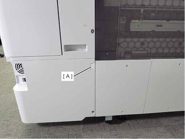
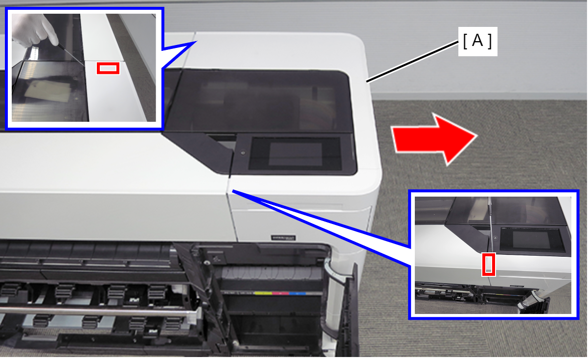
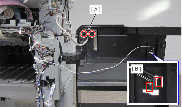
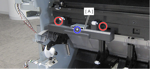
Remove the two screws, and remove the Maintenance Cover (A).
- : : Silver M3x8 Cup S-tite screw
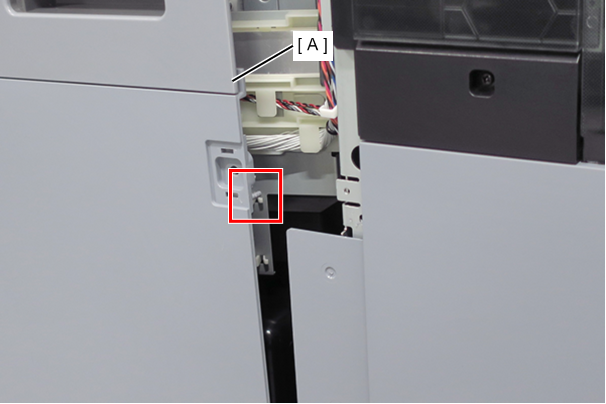
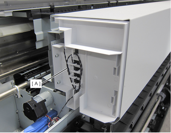
- Remove the cable (B) from the relay connector (A).
Release the cable (B) from three clamps.
 Check Point / チェックポイント
If the cable/clamp is covered with a plastic sheet, work while avoiding the plastic sheet.
Assemble / 組み立て- Push the two dowels (A) of the Maintenance Cover (A) in the positioning holes of the case.
- Push the two dowels (A) of the Maintenance Cover (A) in the positioning holes of the case.
- Detach the Ink Ink Cartridge Cover (A) from the three shafts. (Only perform for SC-P8500D series/SC-T7700D series/SC-T5700D series/SC-P6500D series/SC-P6500DE series/SC-T3700D series/SC-T3700DE series/SC-P6500E series/SC-T3700E series/SC-P8500DM series/SC-T7700DM series/SC-T5700DM series)
- Remove the six screws. (Only perform for SC-P8500D series/SC-T7700D series/SC-T5700D series/SC-P6500D series/SC-P6500DE series/SC-T3700D series/SC-T3700DE series/SC-P6500E series/SC-T3700E series/SC-P8500DM series/SC-T7700DM series/SC-T5700DM series)
- : Silver M3x8 Cup S-tite screw
Release the dowel of the Ink Holder Housing (A), and remove it frontward. (Only perform for SC-P8500D series/SC-T7700D series/SC-T5700D series/SC-P6500D series/SC-P6500DE series/SC-T3700D series/SC-T3700DE series/SC-P6500E series/SC-T3700E series/SC-P8500DM series/SC-T7700DM series/SC-T5700DM series)
 Caution / 注意
Carefully remove the Ink Holder Housing not to pull the cables connected to the cover.
Assemble / 組み立て- When removing the Ink Holder Housing (C) to remove another part or component, remove the sensor (B) from the relay connector (A), and then place the cover beside the printer.
- If the ink tube (A) is detached from the hook of the Ink Bifurcated Flow Channel Unit (B), set the tube properly, or ink may not be supplied to the ink tube, resulting in print failure.
Remove the two screws , and remove the USB cable (A). (Only perform for SC-P8500D series/SC-T7700D series/SC-T5700D series/SC-P6500D series/SC-P6500DE series/SC-T3700D series/SC-T3700DE series/SC-P6500E series/SC-T3700E series)
- Disengage the sensor (B) from the two hooks. (Only perform for SC-P8500D series/SC-T7700D series/SC-T5700D series/SC-P6500D series/SC-P6500DE series/SC-T3700D series/SC-T3700DE series/SC-P6500E series/SC-T3700E series)
- : Silver M3x8 P-tite screw
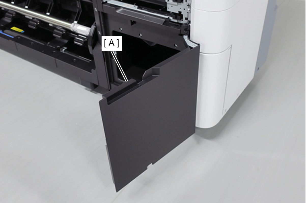
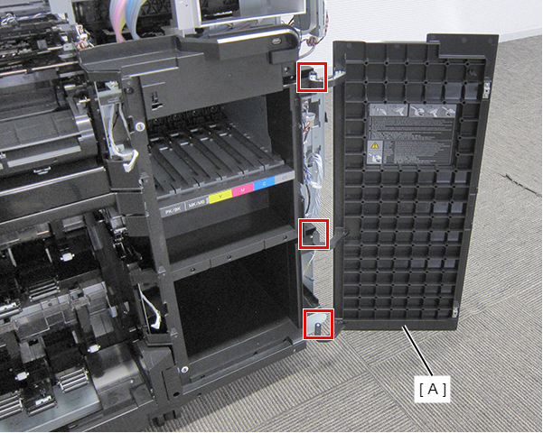
- Open the Front Cover (A). (Only perform for SC-P6550E series/SC-T3750E series)
- Release the dowels of the Front Cover (A) in the order shown in the figure below, and remove. (Only perform for SC-P6550E series/SC-T3750E series)
- Remove the four screw, and remove the Rear Cover (A). (Only perform for SC-P6550E series/SC-T3750E series)
- : Black M3x8 Cup S-tite screw with plastic washer
- : Black M3x8 Cup S-tite screw
- Remove the 2 screws and remove the Left Cover (A) in the direction of the arrow. (Only perform for SC-P6550E series/SC-T3750E series)
- : Black M3x8 Cup S-tite screw
- Remove the 2 screws and remove the Right Cover (A). (Only perform for SC-P6550E series/SC-T3750E series)
- : Black M3x8 Cup S-tite screw
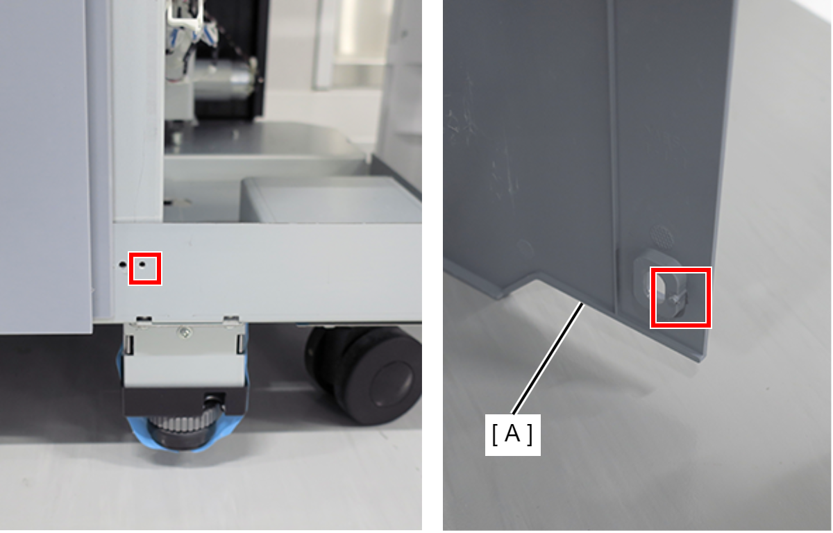
- Pull out the Lower Spindle Holder (A).
- Pull out the Inner Home Side Lower Cover (B) to the front to remove.
- : Silver M3x8 Cup S-tite screw
- Remove the screw.
- : Silver M3x8 Cup S-tite screw
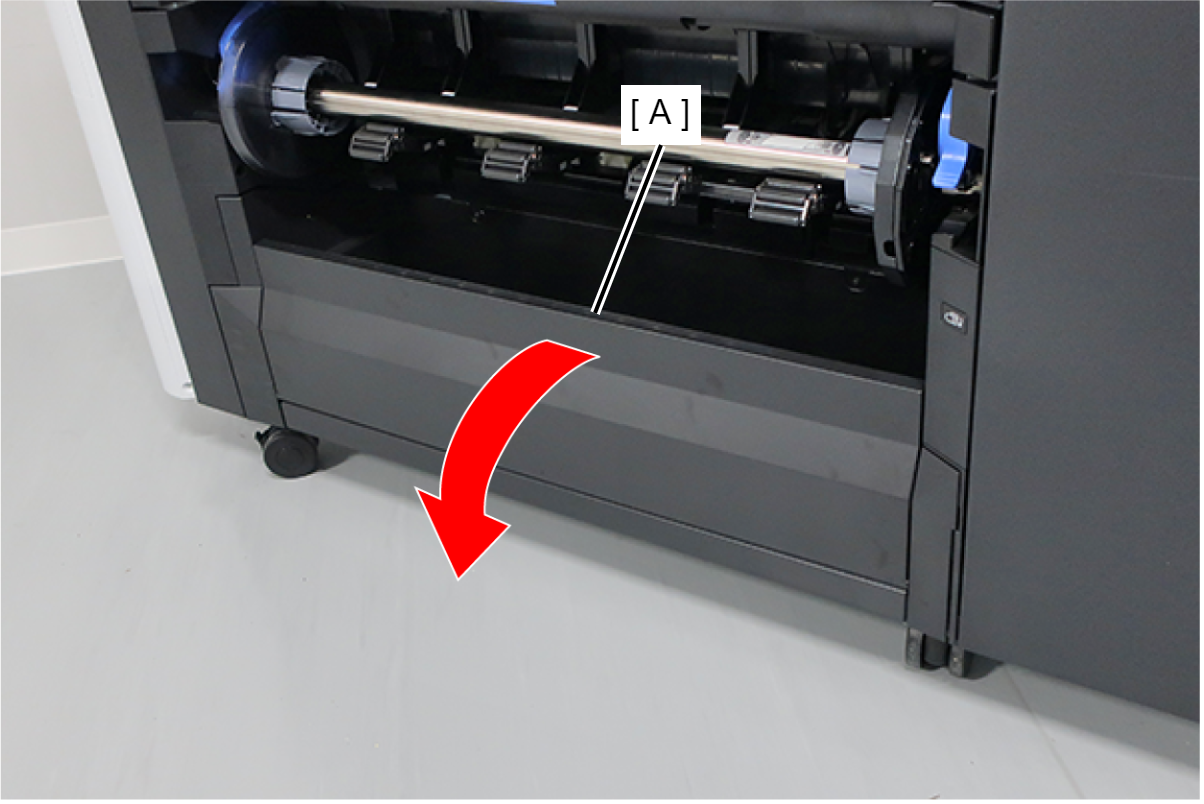
- Raise the paper guide (A), and remove the screw.
- : Silver M3x8 Cup S-tite screw
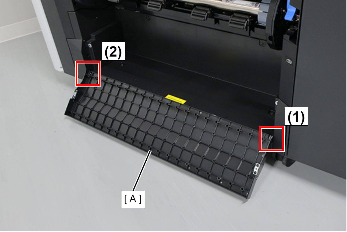
- Pull out the Paper Basket Unit (A).
- Pull out the Inner Home Side Upper Cover (B) to the front to remove.
- Pull out the Lower Spindle Holder (A).
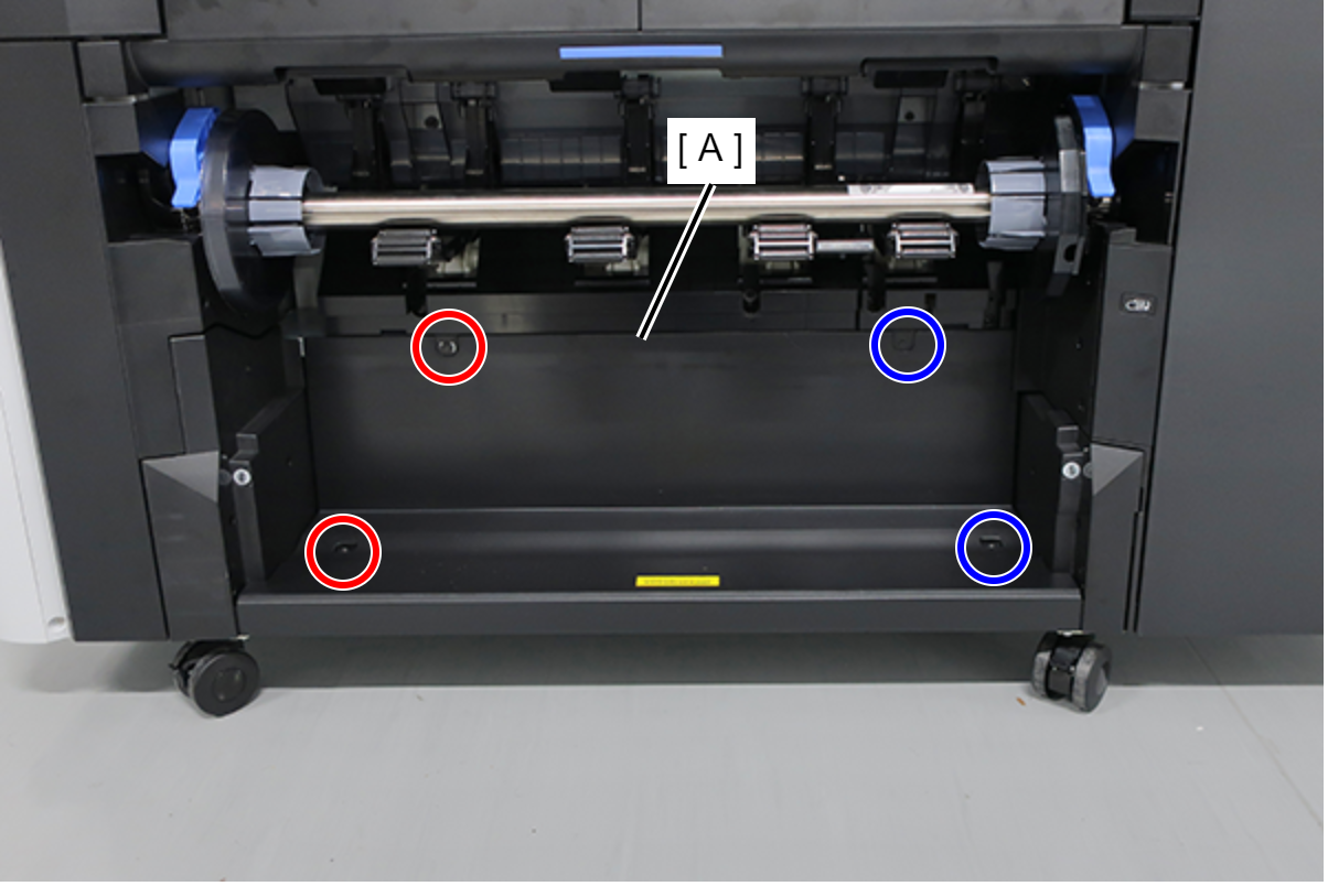
- Remove the 5 screws.
- : Silver M3x8 Cup S-tite screw
- Raise the paper support (A), and remove the screw.
- : Silver M3x8 Cup S-tite screw
- Pull out the Inner Full Side Cover (A) to the front to remove.
- Remove the four screws and then remove the Housing Support Plate.
- : Silver M3x8 Cup S-tite screw
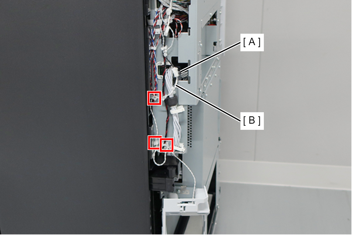
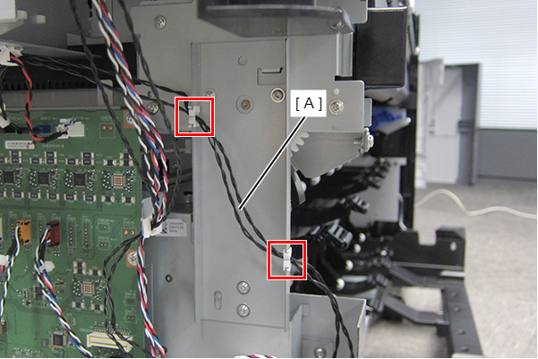
Release the cable (A) from two clamps.
- Remove the four screws, and remove the Grounding Plate (A).
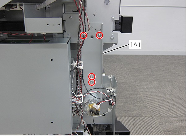
- : Silver M3x8 Cup S-tite screw
- Remove the two screws and remove the frame (A). (SC-P8500DL series/SC-T7700DL series only)
- : Silver M3x4 Bind machine screw
- Remove the four screws.
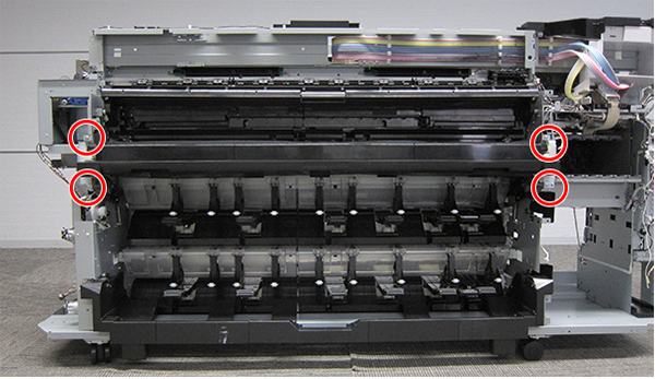
- : Silver M4x8 Cup S-tite screw
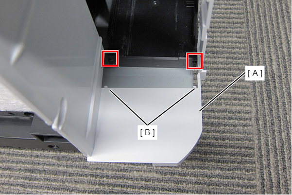
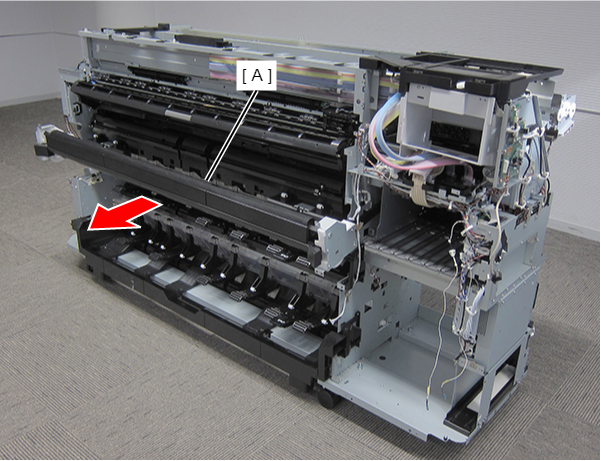
Remove the Paper Basket Unit (A) frontward.
 Assemble / 組み立て
- Remove the two pieces of blue tape (A) from both sides before attaching the new Paper Basket Unit to the printer.
- Remove the three polyethylene sheets (B) after attaching the Paper Basket Unit to the printer.
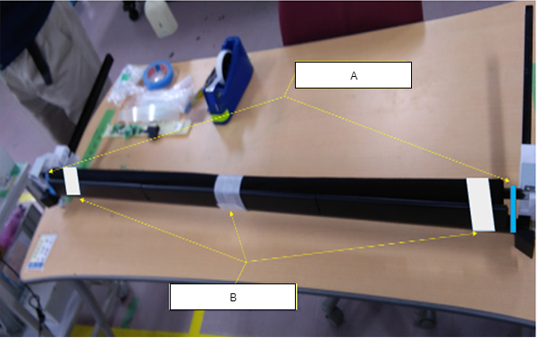
- Insert the Paper Basket Unit horizontally into the printer.
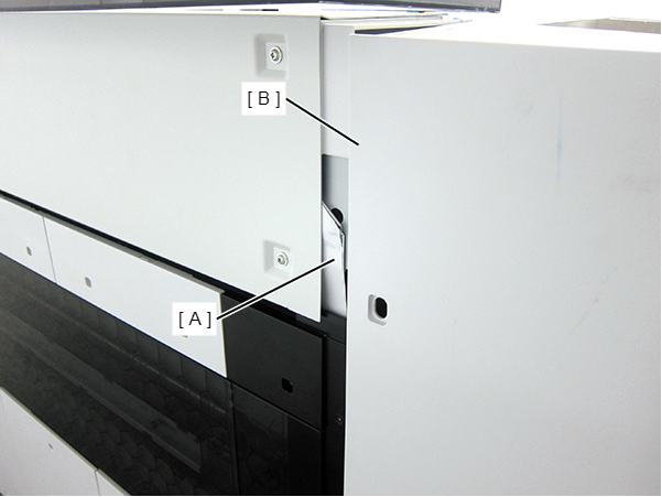
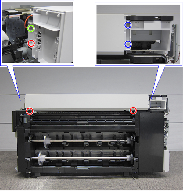
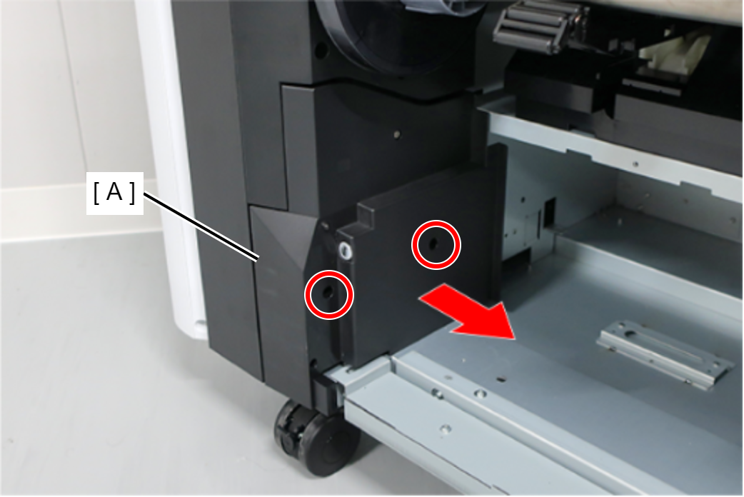
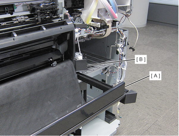
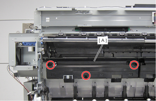
- Remove the three screws and remove the Front Paper Guide Left Support (A).
- : Silver M3x10 Cup P-tite screw
- : Silver M3x8 Cup S-tite screw
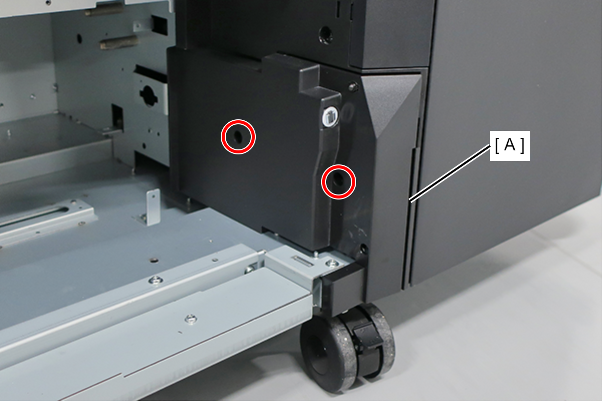
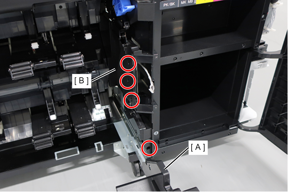
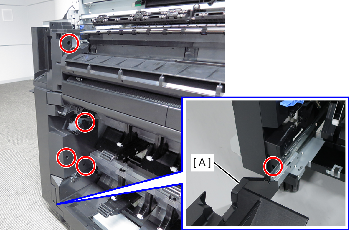
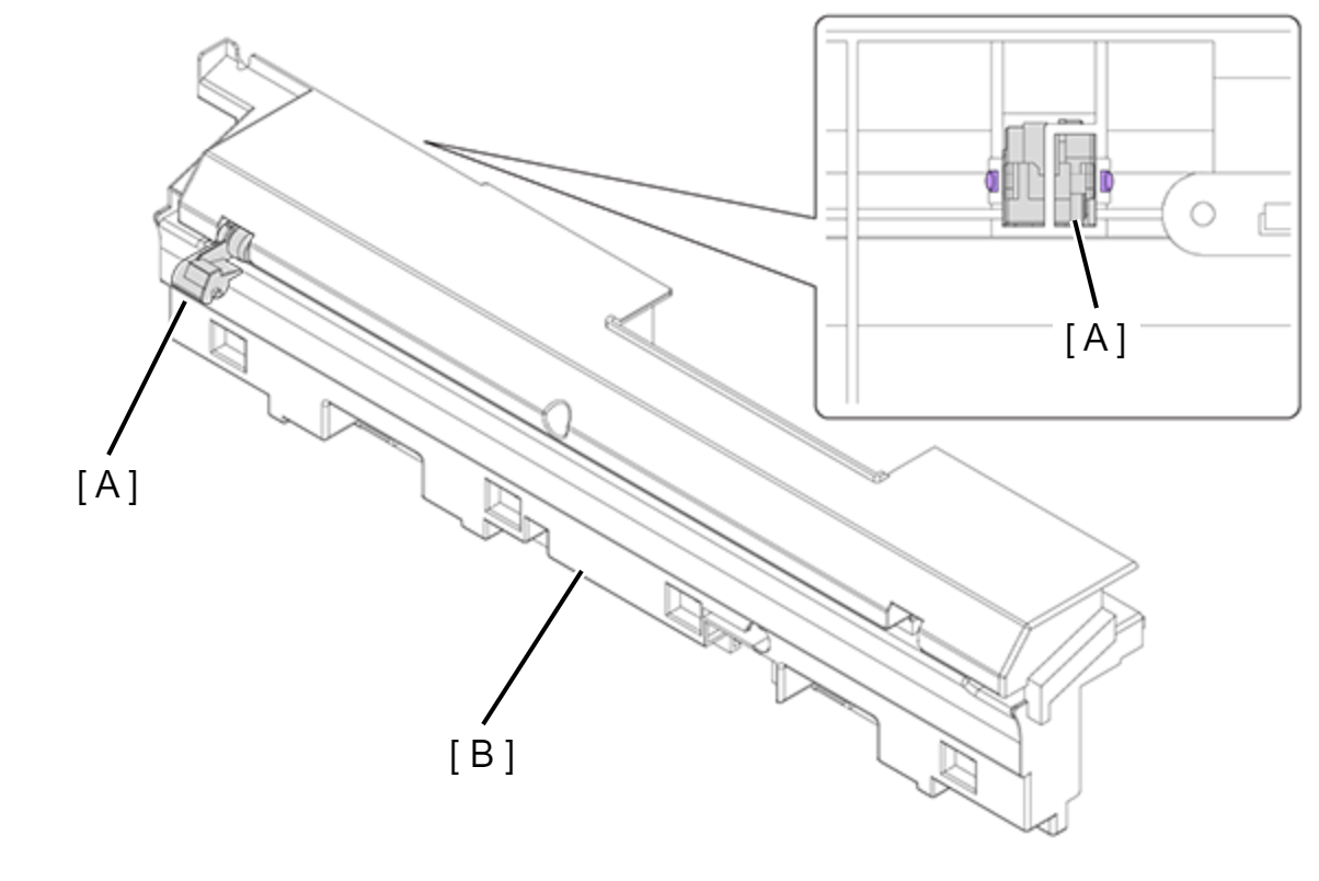
- Remove the three screws and remove the Front Paper Guide Left (A).
- : Silver M3x8 Cup S-tite screw
Caution / 注意When the roller (A) is removed from the Front Paper Guide Left (B), align the 2 dowels of the roller (A) with the Front Paper Guide Left (B) positioning holes to install.
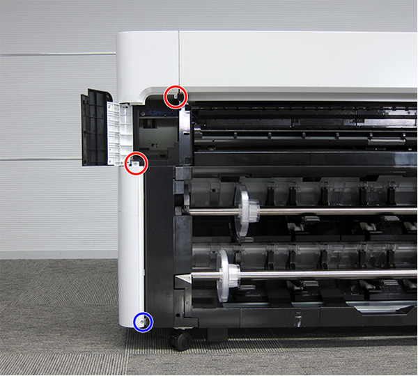
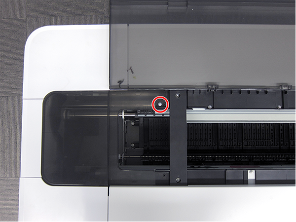
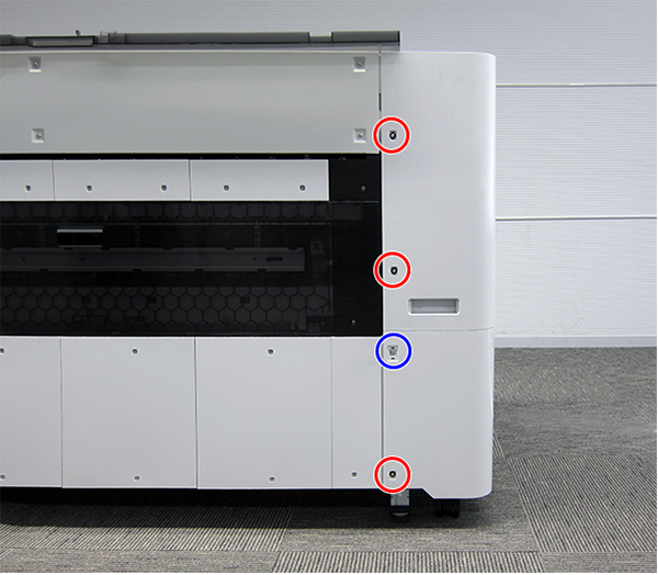
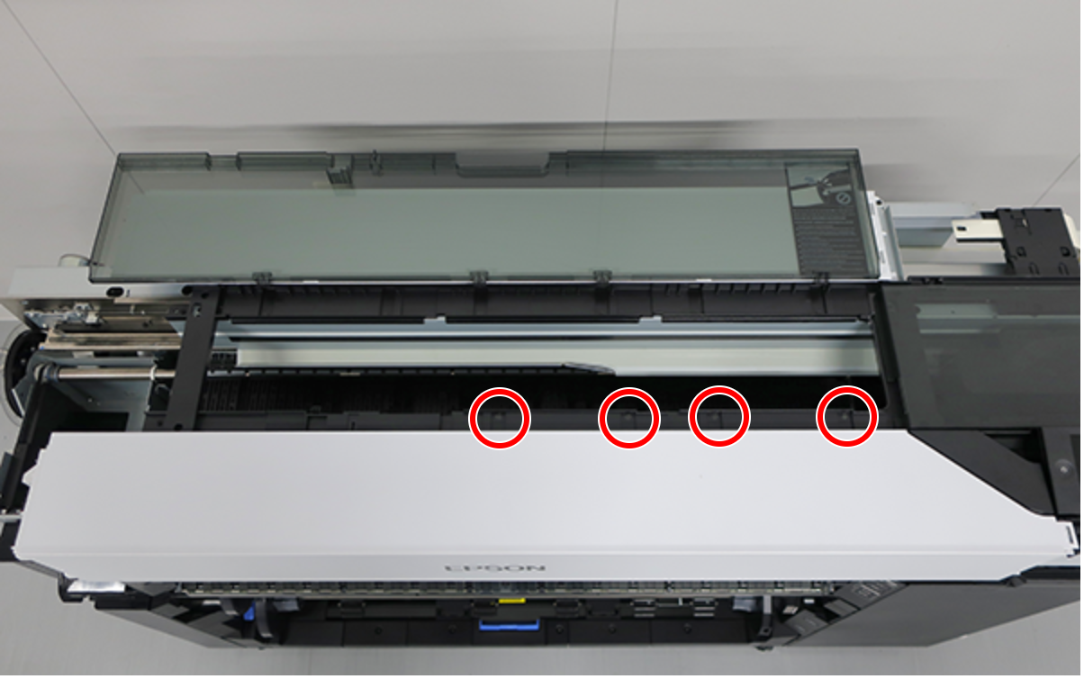
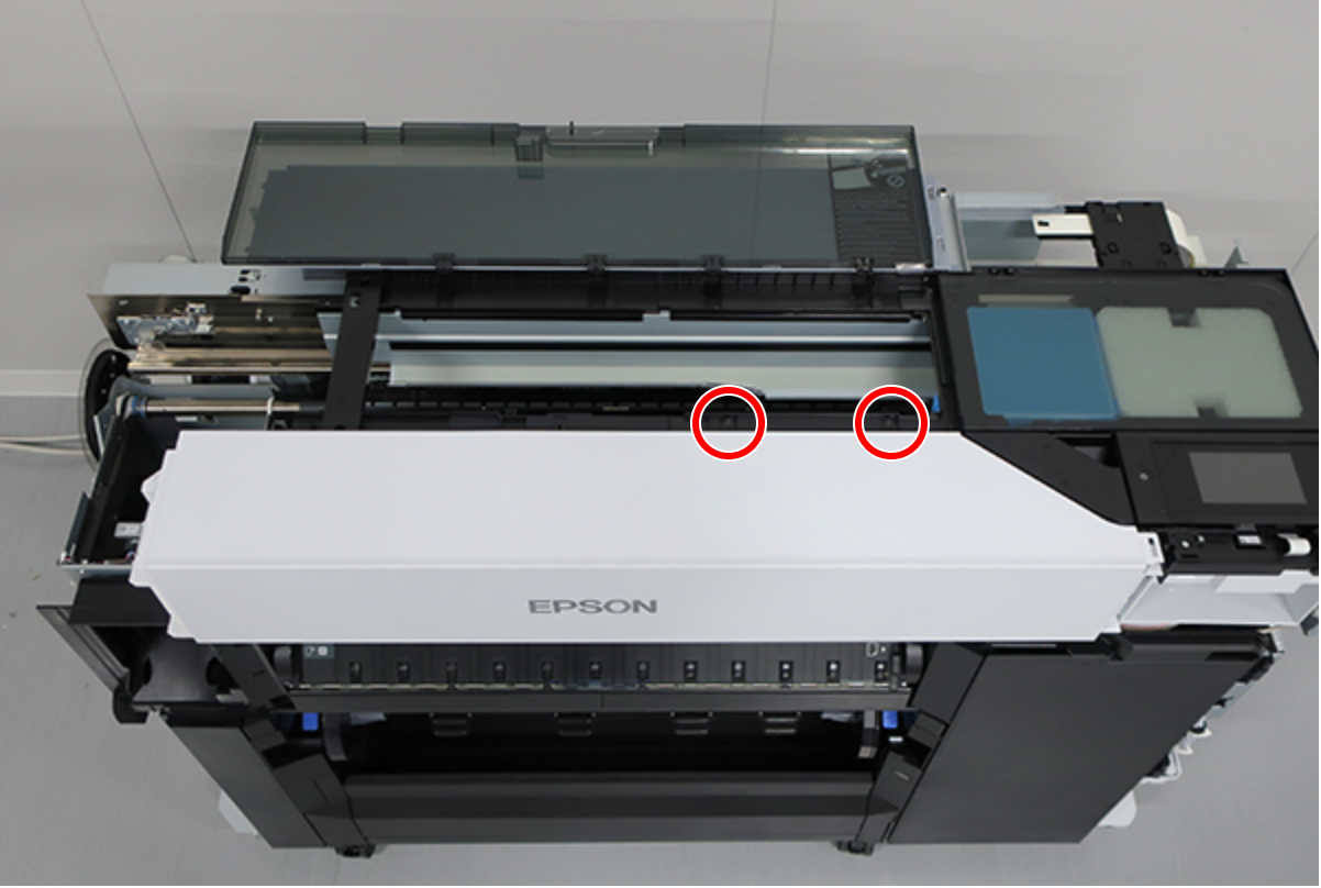
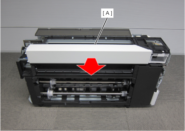
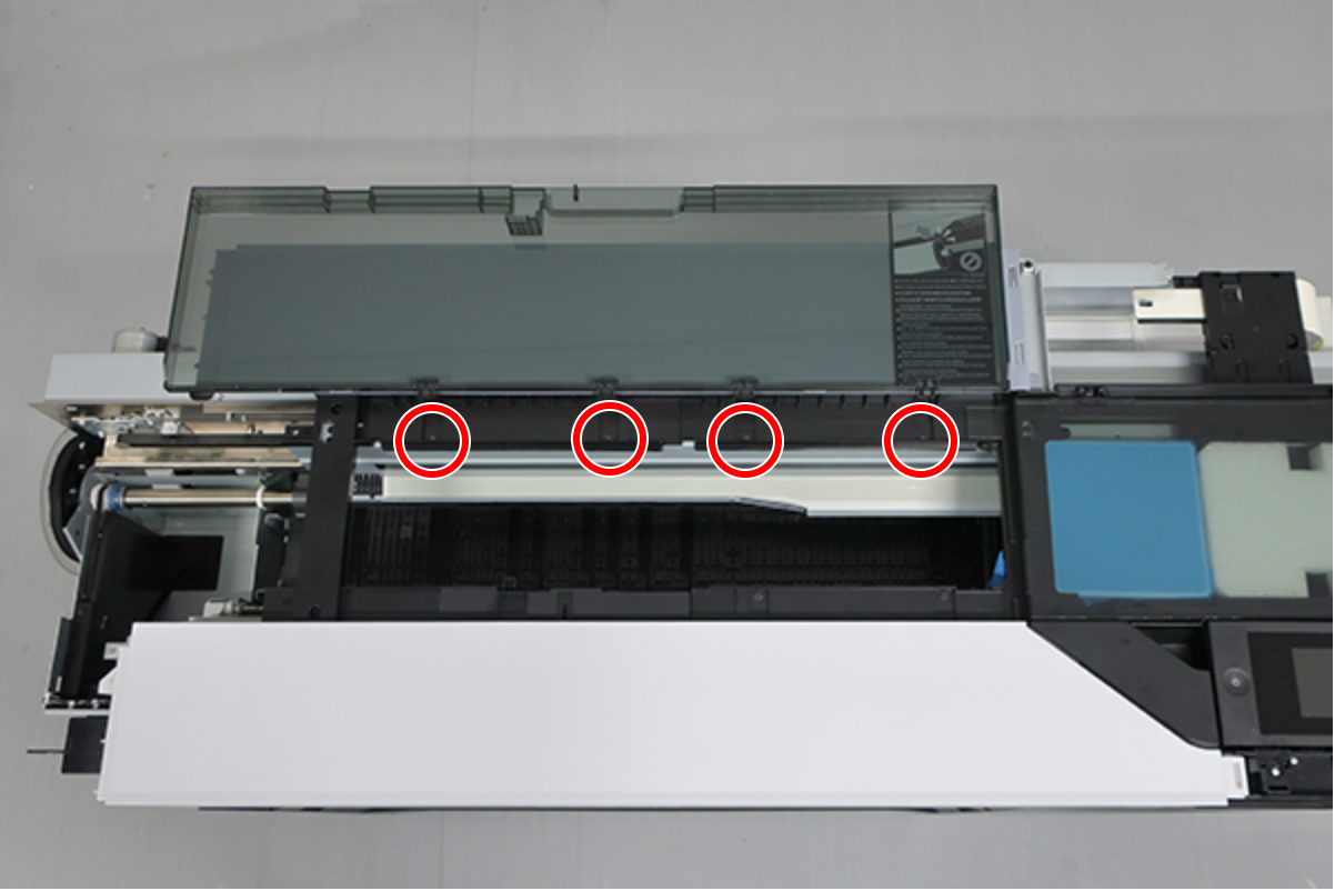
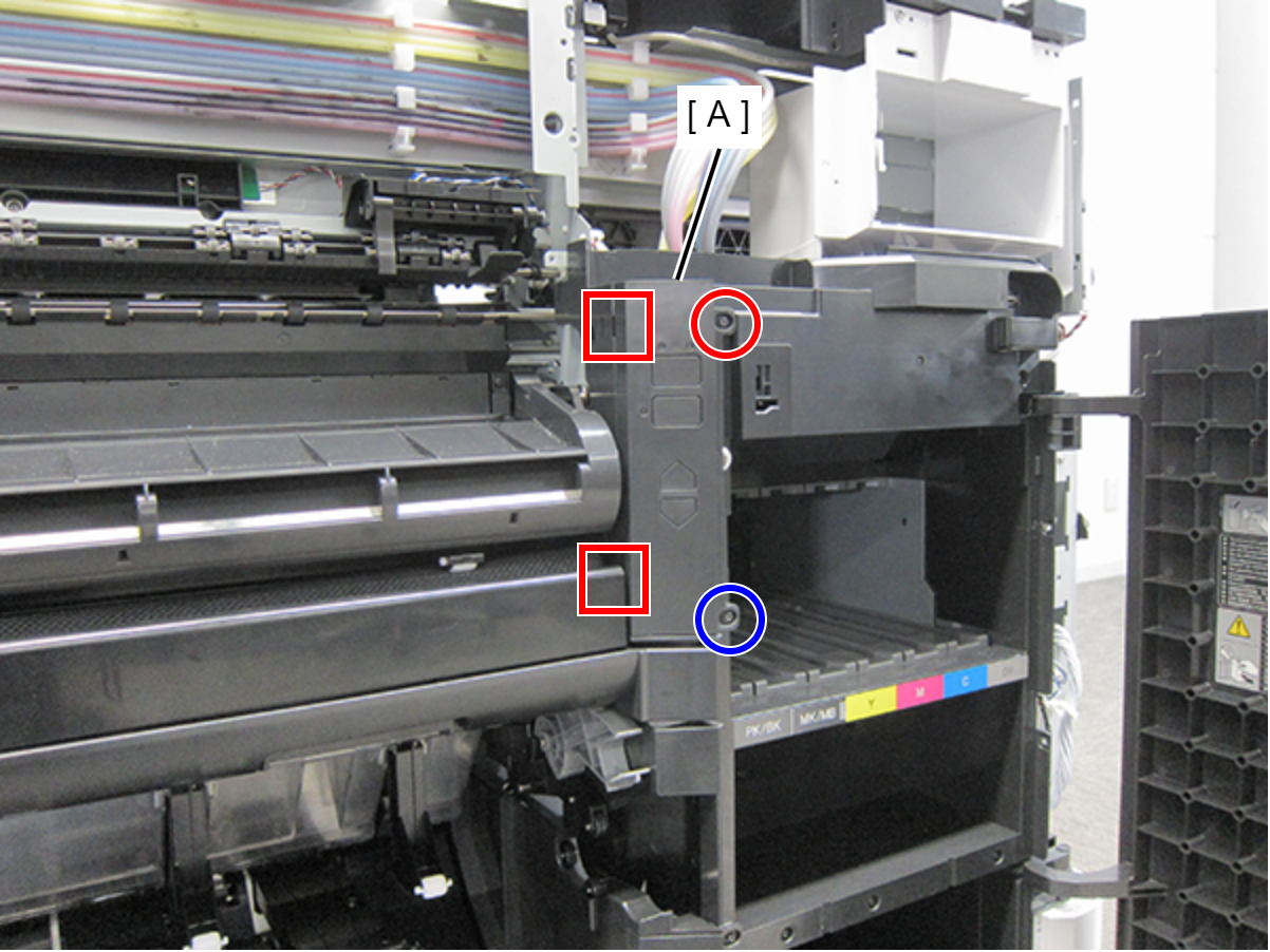
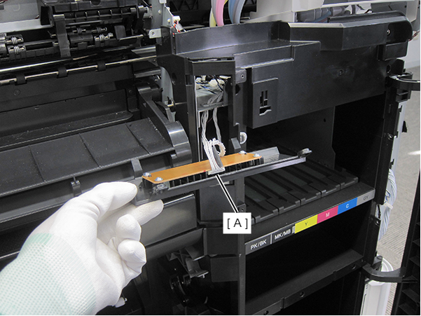
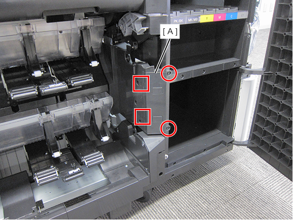
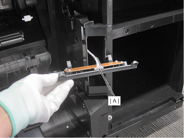
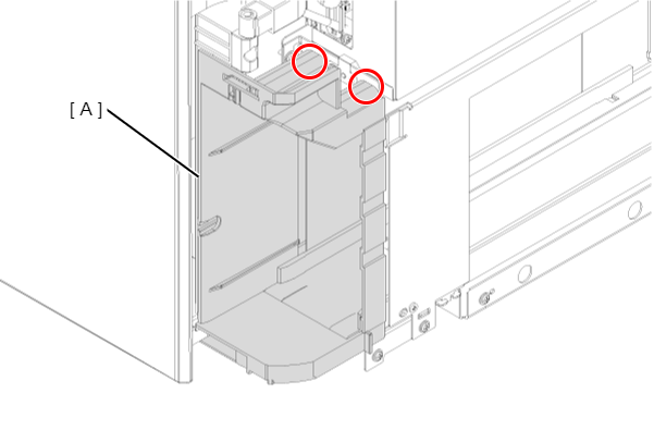
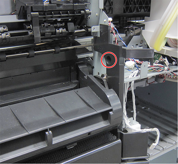
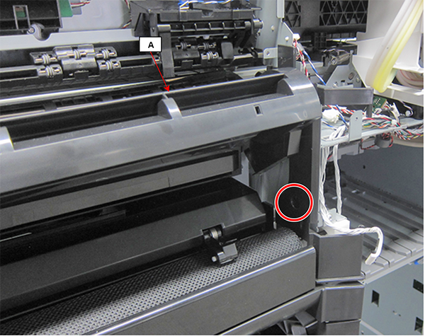
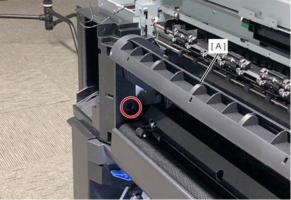
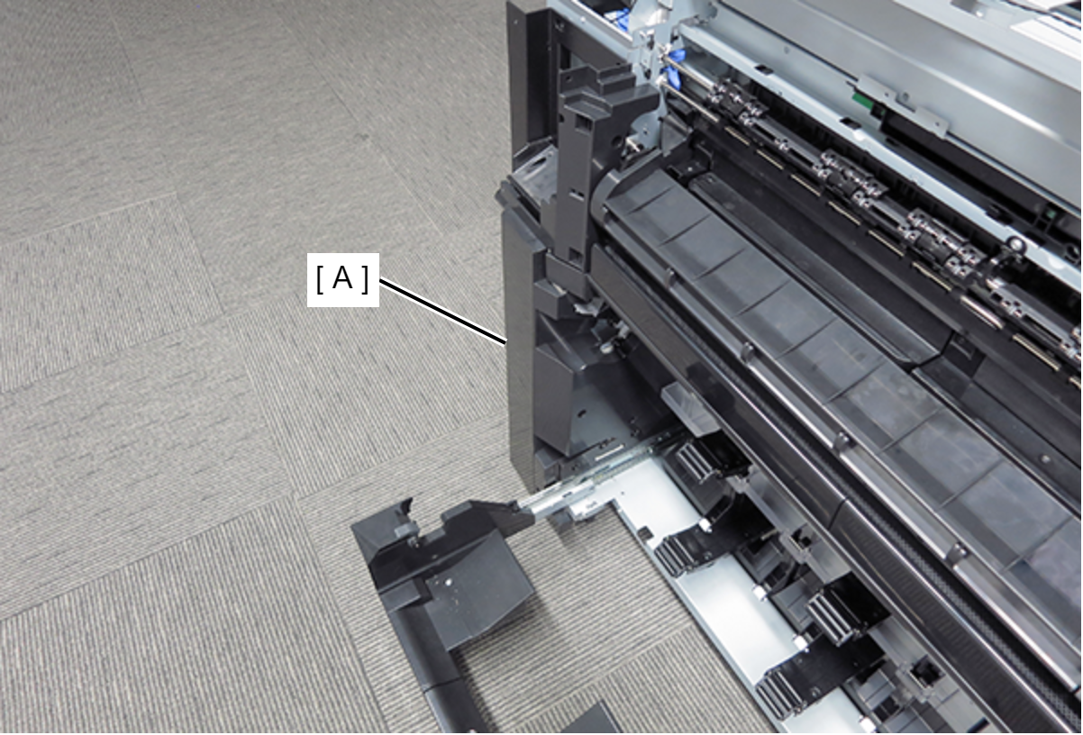
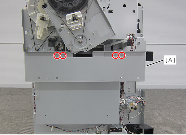
- Remove the two screws and remove the Front Paper Guide Middle (A).
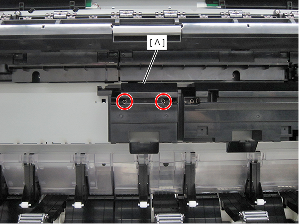
- : Silver M3x8 Cup S-tite screw