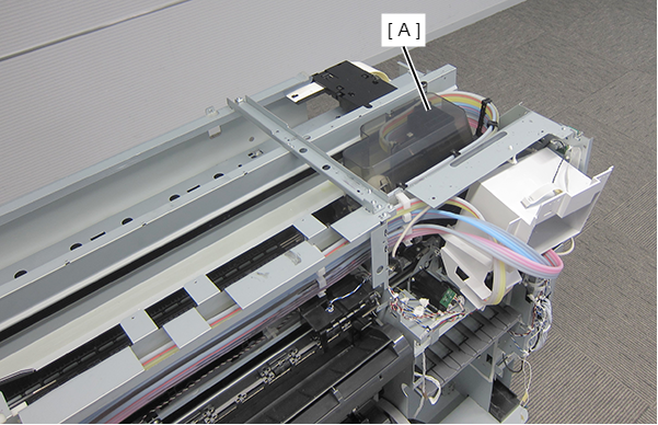
CR Encoder
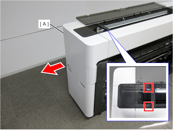
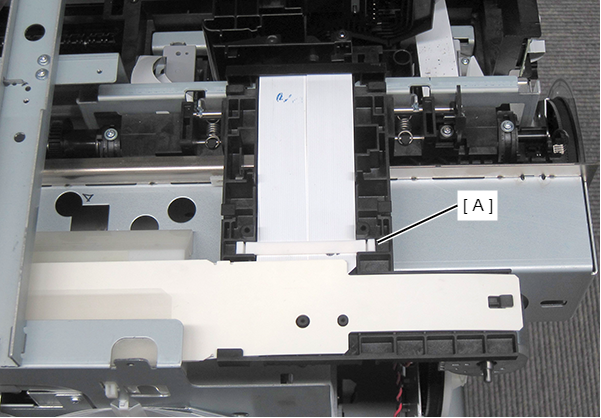
- Remove the single screw and remove the cover (A).
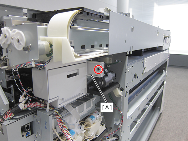
 : Silver M3x10 Cup P-tite screw
- Insert a screwdriver and rotate the CR Manual Unlock Gear (A) counter-clockwise.
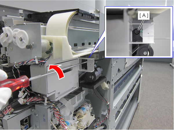
CR locked state
CR unlocked state
- Move the CR Unit (A) to the Full side.
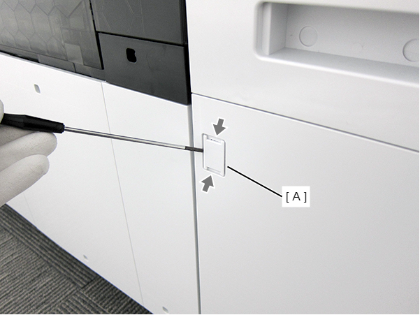
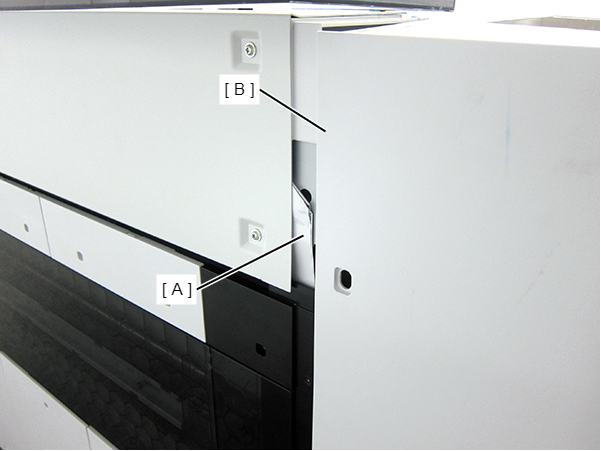
- Insert a flathead screwdriver and release the two hooks, and remove the screw cover (A).
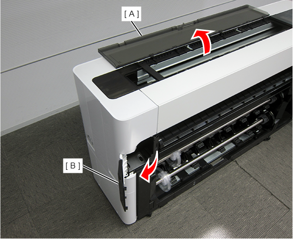
- Open the Printer Cover (A) and the Cutter Cover (B).
- Remove the three screws at the front side.
- : Silver M3x10 Cup P-tite screw
 : : Silver M3x8 Cup S-tite screw
- Remove the screw at the top side.
- : : Silver M3x8 Cup S-tite screw
- Remove the four screws at the rear side.
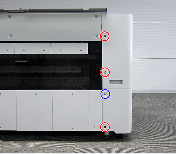
- : Silver M3x8 Cup S-tite screw with plastic washer
- : : Silver M3x8 Cup S-tite screw
- Remove the four screws at the left side.
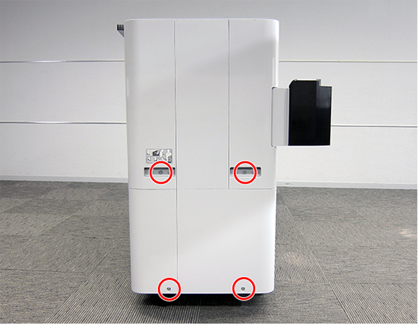
- : Silver M3x8 Cup S-tite screw
- : Silver/M4x8/machine screw
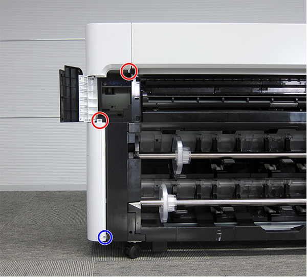
On the printer rear side, release the dowel of the Full Side Cover Unit (A).
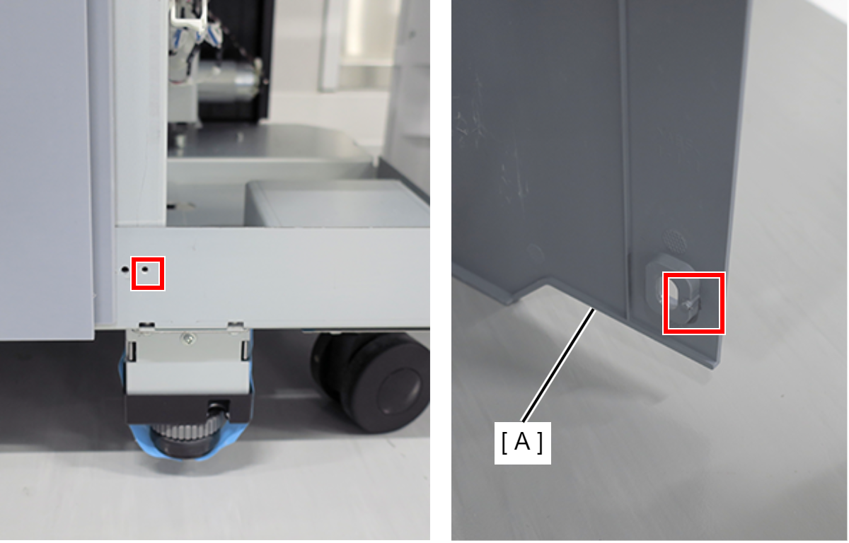
Remove the Full Side Cover Unit (A) from the dowels, and remove it while it in the direction of the arrow.
 Assemble / 組み立て
When installing the Full Side Cover Unit (B), carefully the Head FFC (A) so that it does not damage.
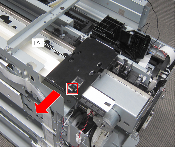
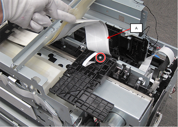
Lift up the tab, and remove the Head FFC Connector Clamp (A) in the direction of the arrow.
 Assemble / 組み立て
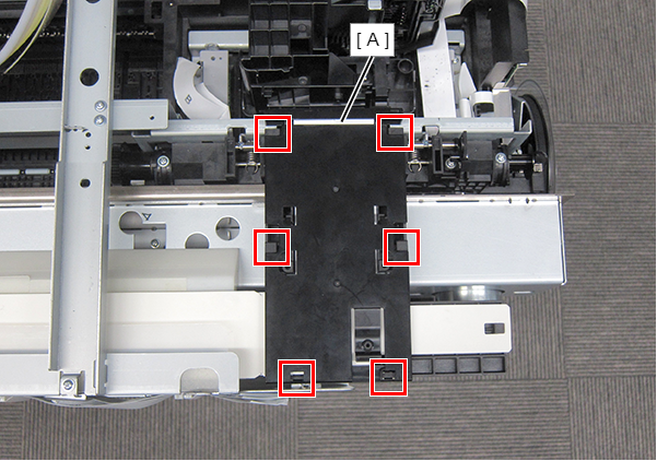
Insert the 6 Head FFC Clamp (A) tabs into the CR Unit positioning holes.
- Remove the Head FFC Control Clamp (A).
- Move the CR Unit to the right side.
- Detach the FFC protection sheets from the four positioning points.
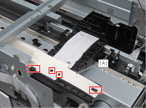
- Lift the Head FFC (A).
- Remove the screw.
- : Silver M3x8 Cup P-tite screw
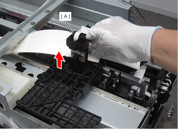
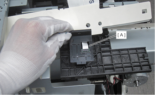
- Remove the CR Encoder Unit (A) upward.
- Remove the FFC (A) from the connector.
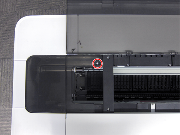
- Remove the two screws, and then remove the CR Encoder (A).
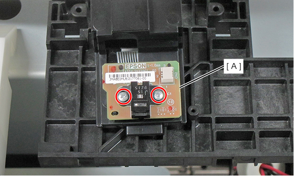
- : Silver M2x10 P-tite screw
 Adjustment / 調整 Adjustment / 調整 |
When removing/replacing this part, refer to following page and make sure to perform the specified operations including required adjustment. |