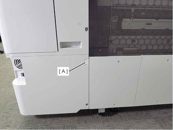
Panel Lower Cover
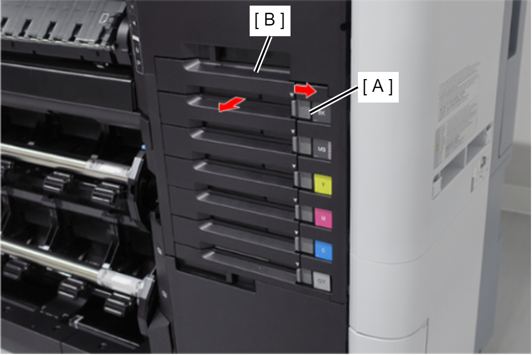
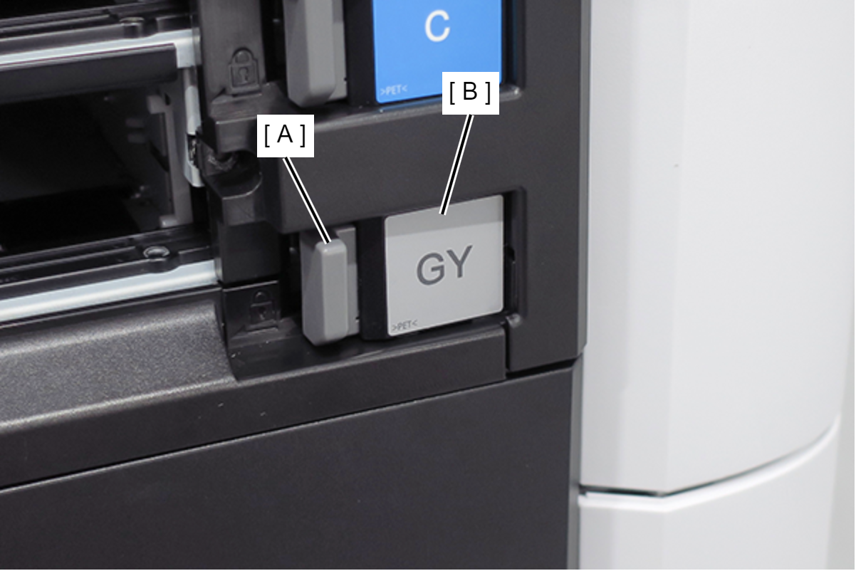
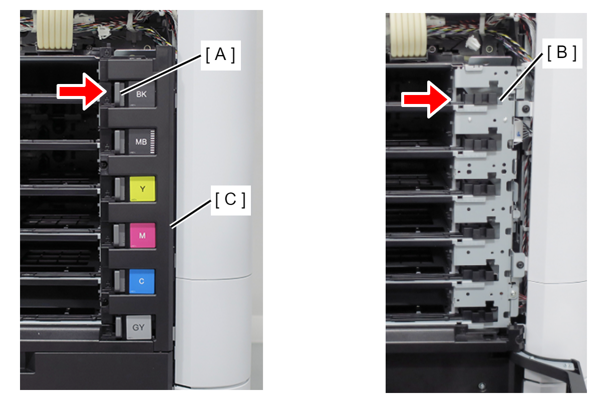
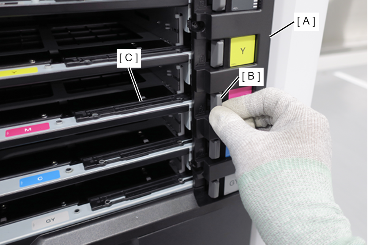
- Release the 6 locks (A), and remove the 6 Ink Pack Trays (B). (Only perform for SC-P8500DL series/SC-T7700DL series)
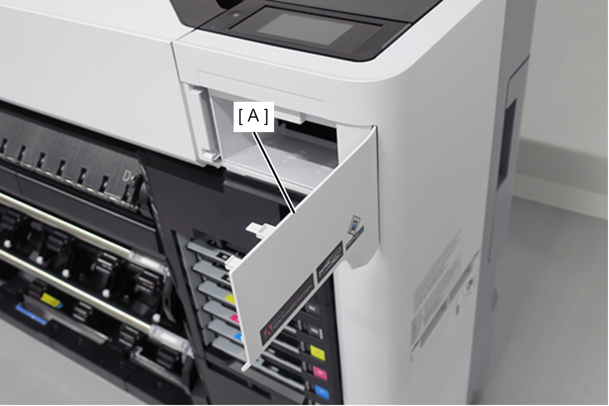
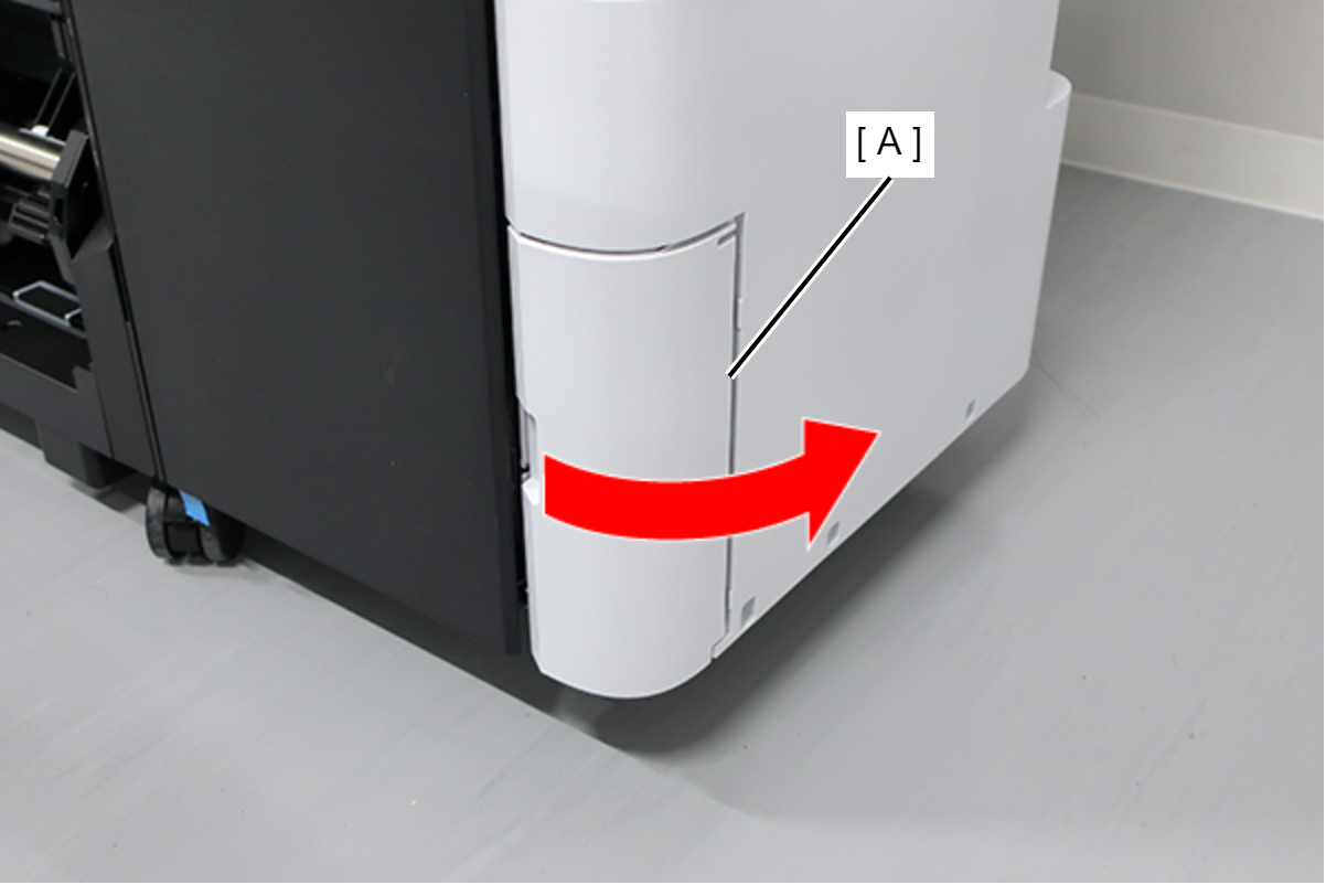
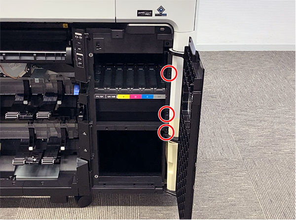
Open the Maintenance Cover (A). (Only perform for SC-P8500DL series/SC-T7700DL series)
- Remove the screw. (Only perform for SC-P8500DL series/SC-T7700DL series)
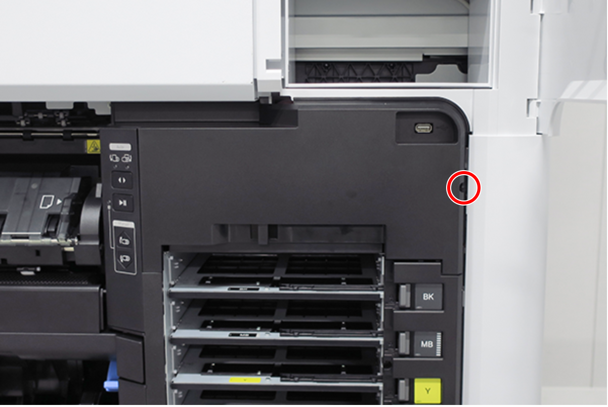
 :Black M3x8 S-tite screw
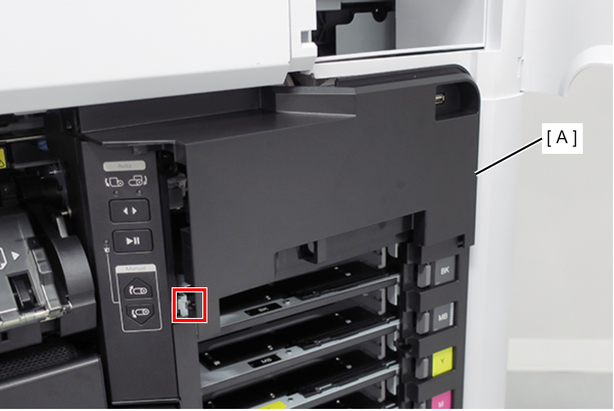
Release the hook, and remove the Ink Holder (RIPS) Upper Cover (A). (Only perform for SC-P8500DL series/SC-T7700DL series)
 Assembly / 組み立て
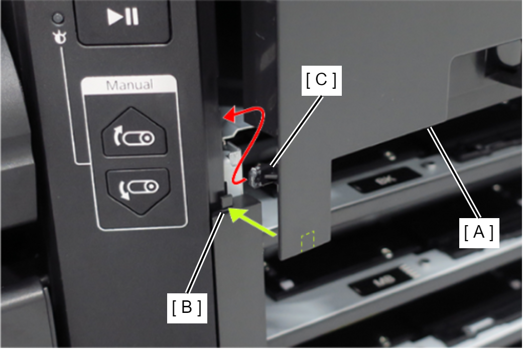
- Insert the Ink Holder (RIPS) Upper Cover (A) tab (B).
- Insert the Ink Holder (RIPS) Upper Cover (A) hook (C).
Remove the two screws, and remove the USB cable (A). (Only perform for SC-P8500DL series/SC-T7700DL series)
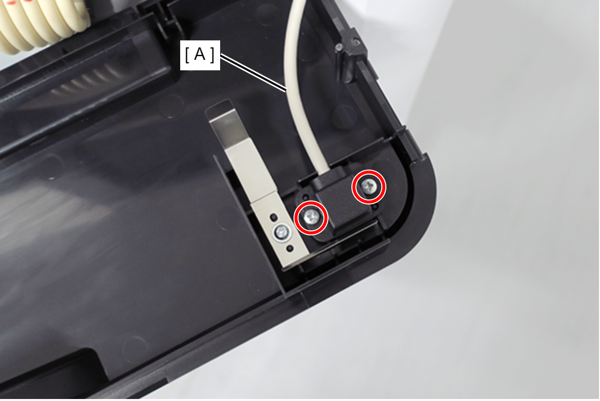
- : Silver M3x8 P-tite screw
Remove the two screws. (Only perform for SC-P8500DL series/SC-T7700DL series)
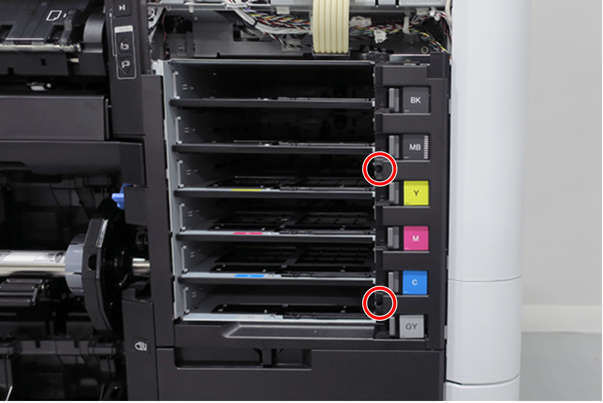
- : Silver M3x8 S-tite screw
- Pull the Ink Pack Tray Right Side (A) slightly forward and release the 2 dowels. (Only perform for SC-P8500DL series/SC-T7700DL series)
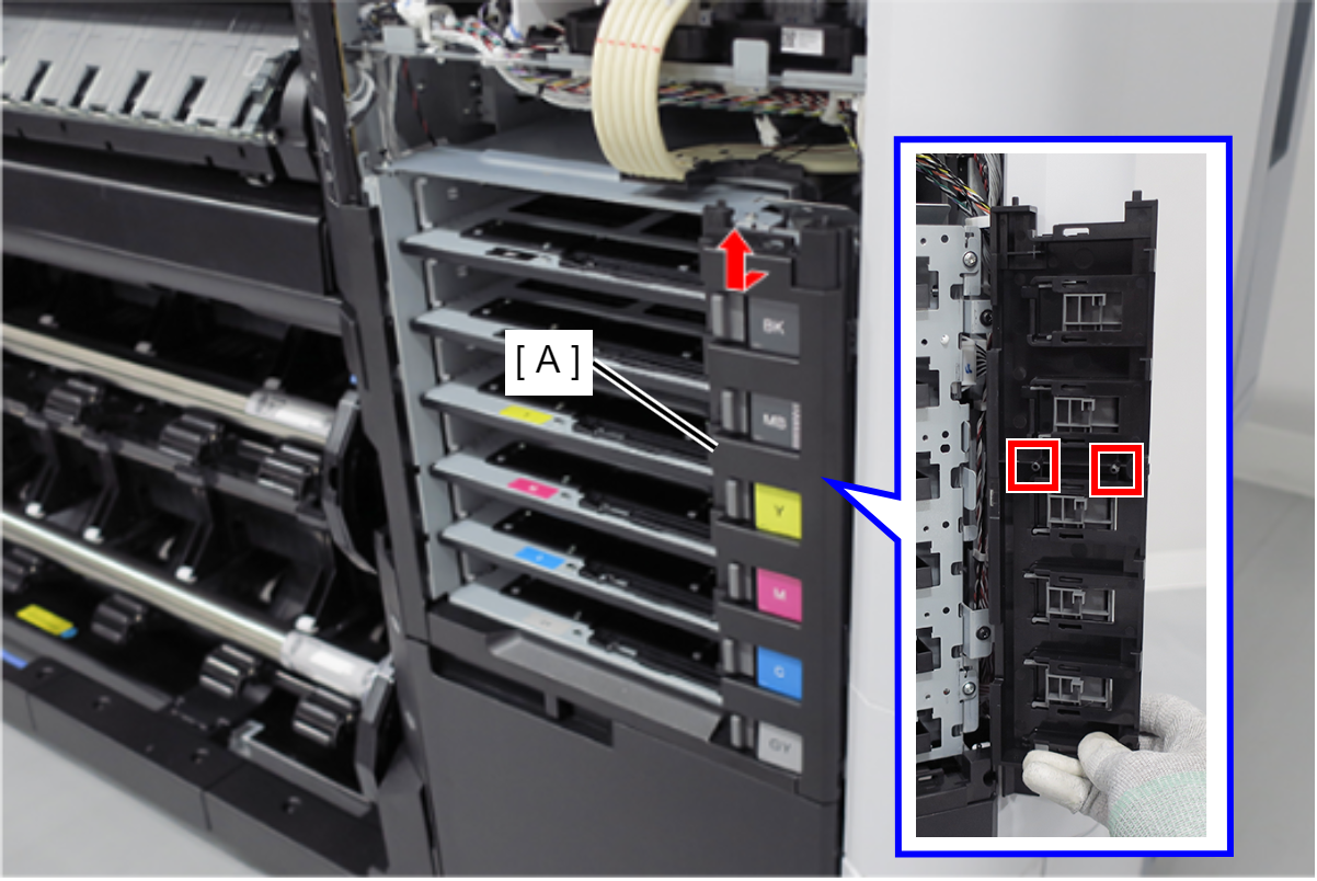
Slide the Ink Pack Tray Right Side (A) upwards to remove. (Only perform for SC-P8500DL series/SC-T7700DL series)
 Assembly / 組み立て
- The gray lock lever (A) and ink plate (B) will come off when removing the Ink Pack Tray Right Side (C). Install them after installing the Ink Pack Tray Right Side (C) in the main unit.
- With the lock lever (A) and tray lever (B) moved to the right side, install the Ink Pack Tray Right Side (C).
- After installing the Ink Pack Tray Right Side (A), move the lock lever (B) and confirm that the tray lever (C) moves in conjunction.
- The gray lock lever (A) and ink plate (B) will come off when removing the Ink Pack Tray Right Side (C). Install them after installing the Ink Pack Tray Right Side (C) in the main unit.
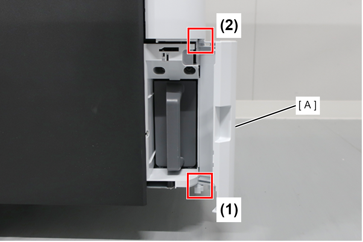
- Open the Maintenance Box Cover (A).
- Release the 2 tabs of the Maintenance Box Cover (A) in the order shown in the figure below, and remove.
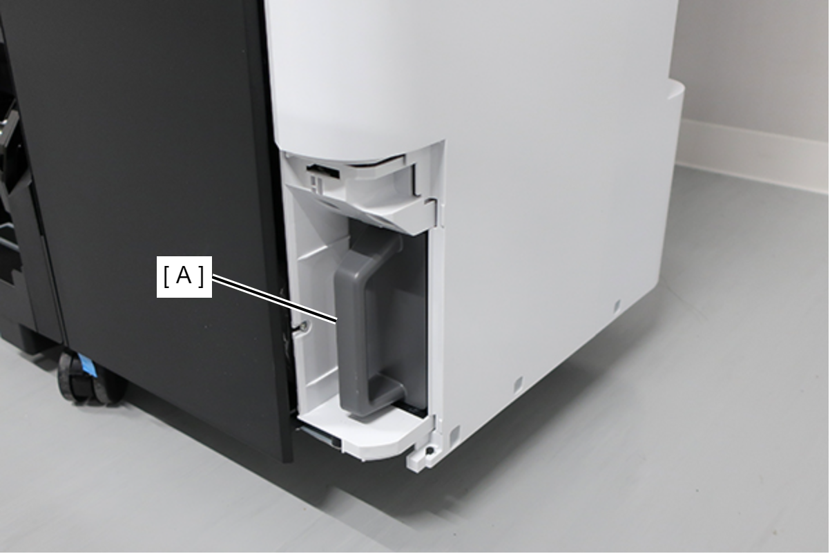
- Remove the Maintenance Box (A).
- Remove the screw.
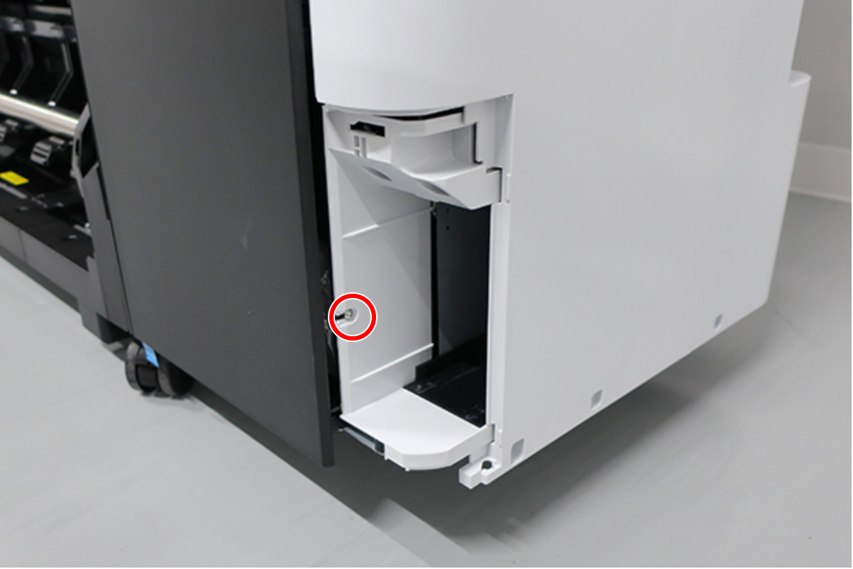
- : : Silver M3x8 Cup S-tite screw
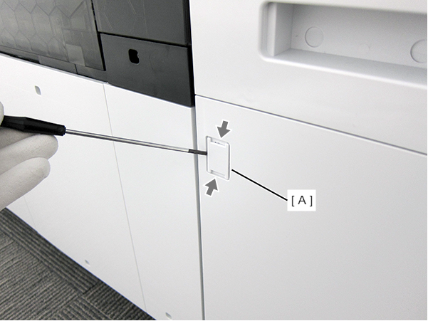
- Insert a flathead screwdriver and release the 2 hooks each, and remove the two screw cover (A).
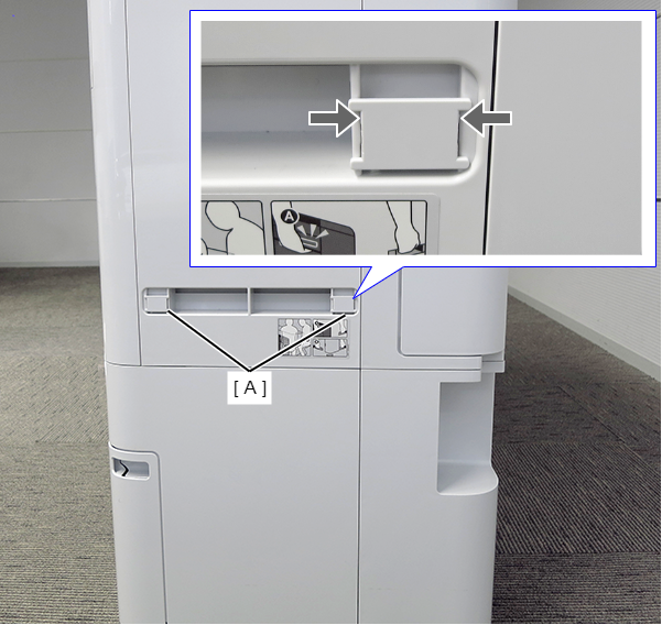
- Insert a flathead screwdriver and release the 2 hooks, and remove the screw cover (A).
- Remove the three screws at the front side.
- : Black M3x8 Cup P-tite screw
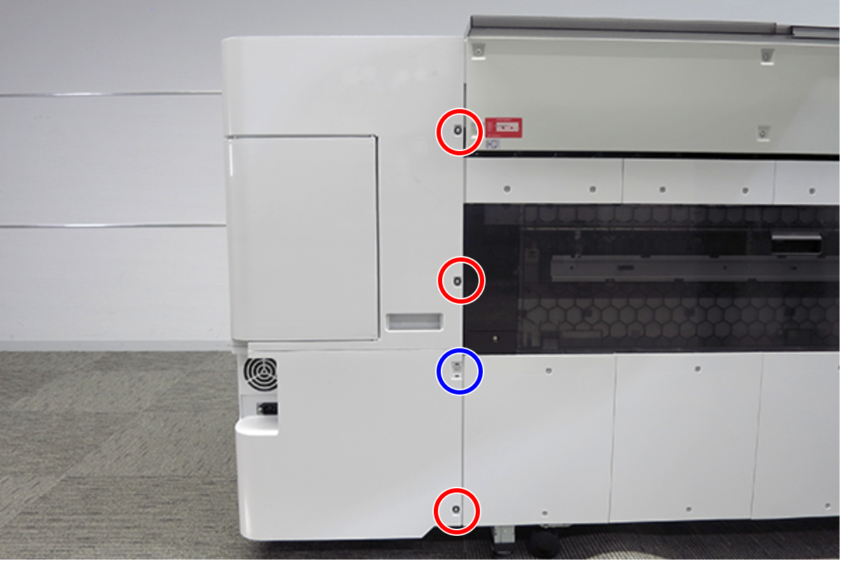
- Remove the five screws at the right side.
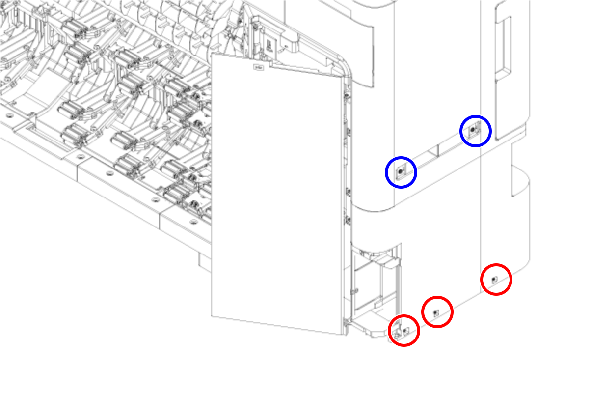
- : Silver M3x8 Cup S-tite screw
 : Silver/M4x8/machine screw
- Remove the four screws at the rear side.
- : Silver M3x8 Cup S-tite screw with plastic washer
- : : Silver M3x8 Cup S-tite screw
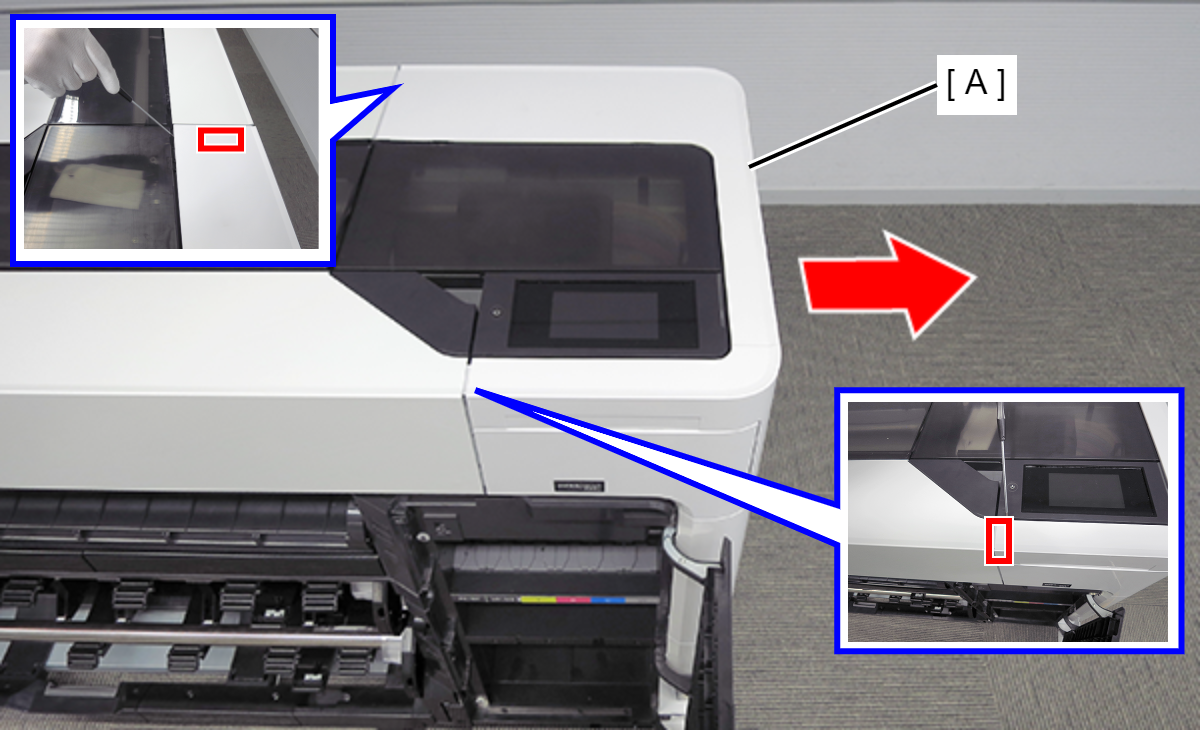
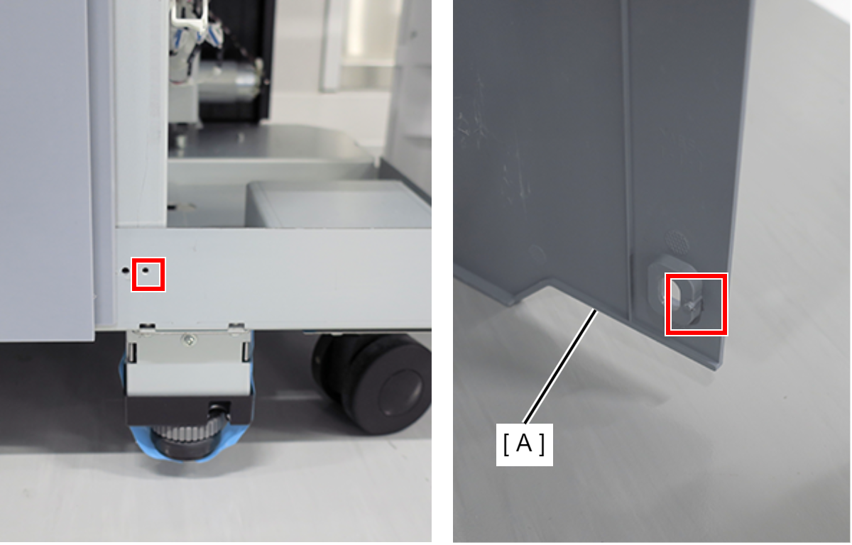
- On the printer rear side, release the dowel of the Home Side Cover Unit (A).
- Insert a flathead screwdriver and release the 2 tabs each, and remove the Home Side Cover Unit (A) in the direction of the arrow.
- Insert a flathead screwdriver and release the two hooks, and remove the screw cover (A).
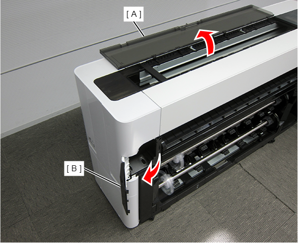
- Open the Printer Cover (A) and the Cutter Cover (B).
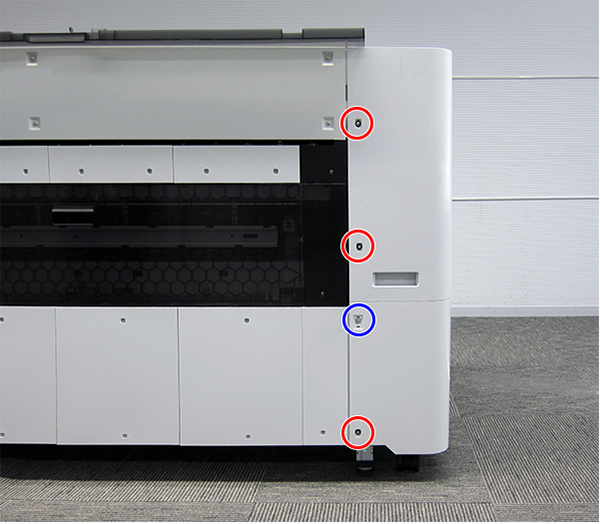
- Remove the three screws at the front side.
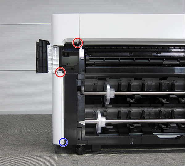
- : Silver M3x10 Cup P-tite screw
- : : Silver M3x8 Cup S-tite screw
- Remove the screw at the top side.
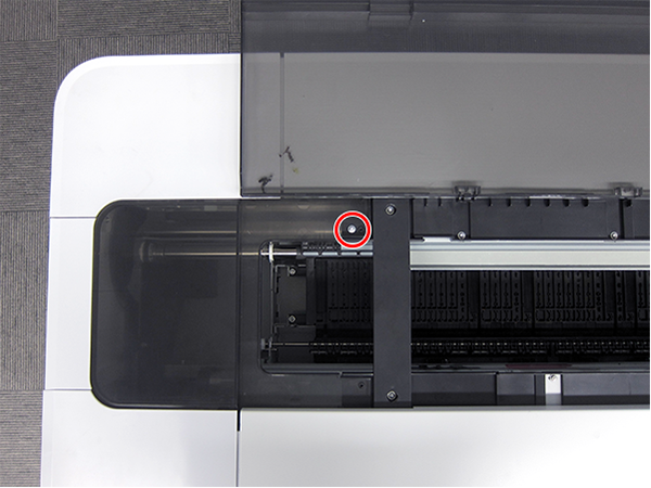
- : : Silver M3x8 Cup S-tite screw
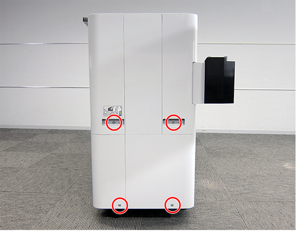
- Remove the four screws at the rear side.
- : Silver M3x8 Cup S-tite screw with plastic washer
- : : Silver M3x8 Cup S-tite screw
- Remove the four screws at the left side.
- : Silver M3x8 Cup S-tite screw
- : Silver/M4x8/machine screw
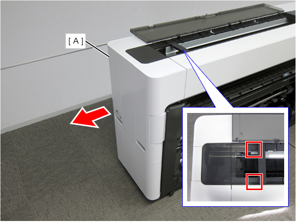
On the printer rear side, release the dowel of the Full Side Cover Unit (A).
Remove the Full Side Cover Unit (A) from the dowels, and remove it while it in the direction of the arrow.
 Assemble / 組み立て
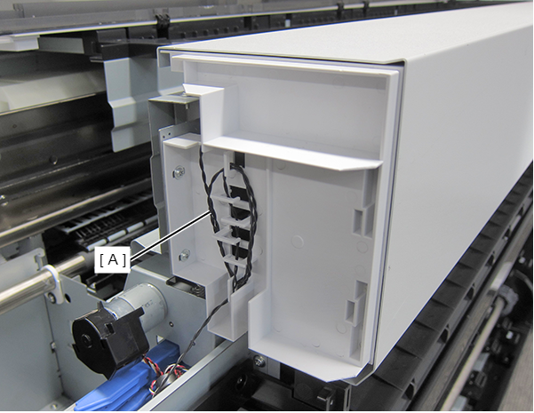
When installing the Full Side Cover Unit (B), carefully the Head FFC (A) so that it does not damage.
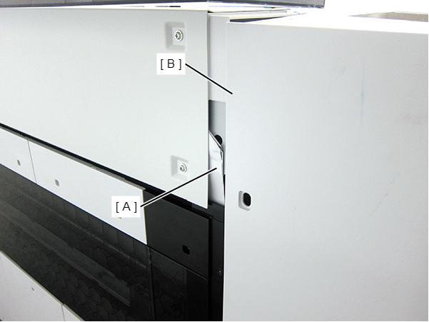
- Release the sensor cable (A). (Only perform for SC-P8500D series/SC-T7700D series/SC-T5700D series/SC-P6500D series/SC-P6500DE series/SC-T3700D series/SC-T3700DE series/SC-P6500E series/SC-T3700E series/SC-P8500DL series/SC-T7700DL series)
- Open the Printer Cover (A). (Only perform for SC-P8500D series/SC-T7700D series/SC-T5700D series/SC-P6500D series/SC-P6500DE series/SC-T3700D series/SC-T3700DE series/SC-P6500E series/SC-T3700E series/SC-P8500DL series/SC-T7700DL series)
Remove the Home Side Top Cover (B). (Only perform for SC-P8500D series/SC-T7700D series/SC-T5700D series/SC-P6500D series/SC-P6500DE series/SC-T3700D series/SC-T3700DE series/SC-P6500E series/SC-T3700E series/SC-P8500DL series/SC-T7700DL series)
Remove the four screws at the front side. (Only perform for SC-P8500D series/SC-T7700D series/SC-T5700D series/SC-P6500D series/SC-P6500DE series/SC-T3700D series/SC-T3700DE series/SC-P6500E series/SC-T3700E series/SC-P8500DL series/SC-T7700DL series)
- (Right):Silver M3x8 Cup S-tite screw
- (Left):SC-P8500D series/SC-T7700D series/SC-P8500DL series/SC-T7700DL series: Silver M3x8 Cup S-tite screw, SC-T5700D series/SC-P6500D series/SC-P6500DE series/SC-T3700D series/SC-T3700DE series/SC-P6500E series/SC-T3700E series: Silver M4x6 Shoulder Screw
 : Silver M3x10 Cup P-tite screw
Assemble / 組み立てTighten the right green screw with the grounding cable. (SC-P8500D series/SC-T7700D series/SC-P8500DL series/SC-T7700DL series only)
- Remove the screws on the top. (Only perform for SC-P8500D series/SC-T7700D series/SC-T5700D series/SC-P6500D series/SC-P6500DE series/SC-T3700D series/SC-T3700DE series/SC-P6500E series/SC-T3700E series/SC-P8500DL series/SC-T7700DL series)
SC-P8500D series/SC-T7700D series/SC-P8500DL series/SC-T7700DL series: 6 pcs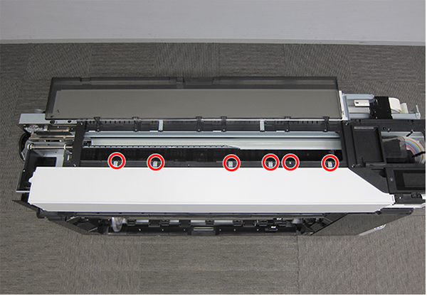
- : Black M3x8 Cup S-tite screw
- : Black M3x8 Cup S-tite screw
- : Black M3x8 Cup S-tite screw
- Remove the Front Top Cover (A) frontward. (Only perform for SC-P8500D series/SC-T7700D series/SC-T5700D series/SC-P6500D series/SC-P6500DE series/SC-T3700D series/SC-T3700DE series/SC-P6500E series/SC-T3700E series/SC-P8500DL series/SC-T7700DL series)
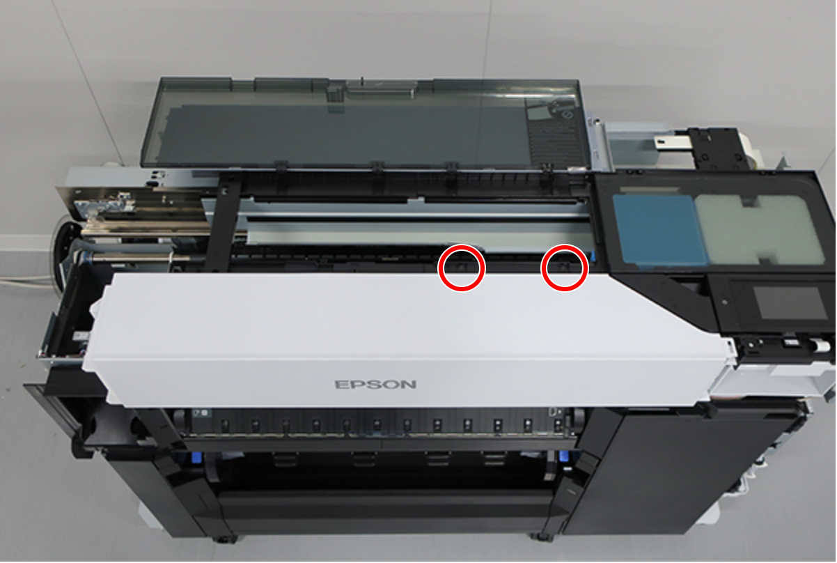
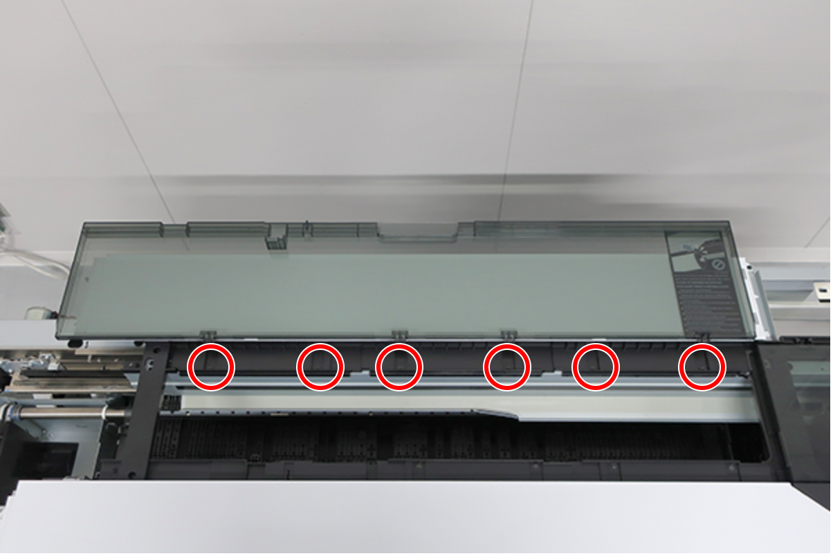
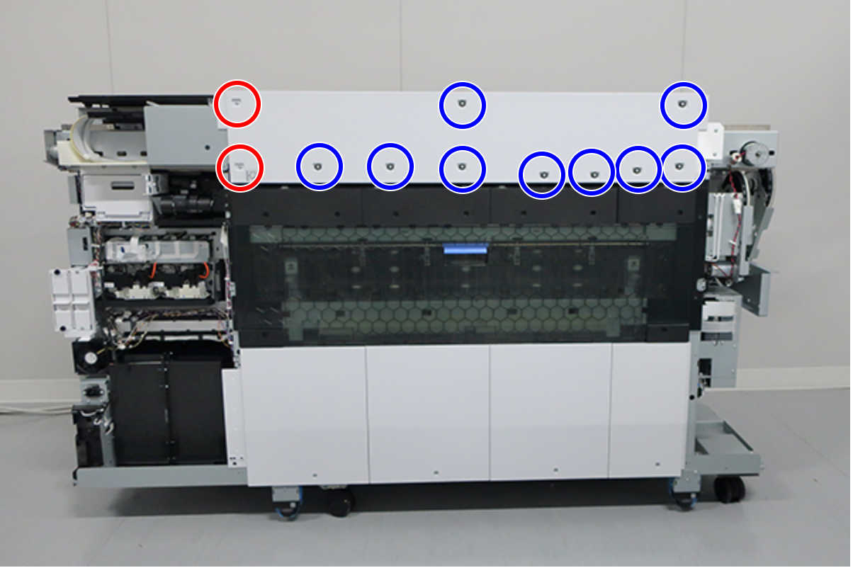
- Remove the screws on the top.
SC-P8500D series/SC-T7700D series/SC-P8500DL series/SC-T7700DL series/SC-P8500DM series/SC-T7700DM series: 8 pcs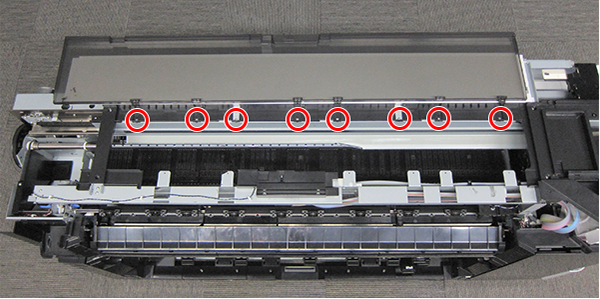
- : Silver M3x8 Cup S-tite screw
- : Silver M3x8 Cup S-tite screw
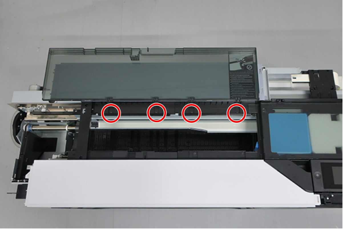
- : Silver M3x8 Cup S-tite screw
- Remove the screws on the back.
SC-P8500D series/SC-T7700D series/SC-P8500DL series/SC-T7700DL series/SC-P8500DM series/SC-T7700DM series: 6 pcs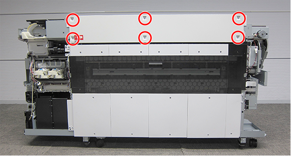
- : Silver M3x8 Cup S-tite screw
- : Silver M3x8 Cup S-tite screw
- : Silver M3x8 Cup S-tite screw with plastic washer
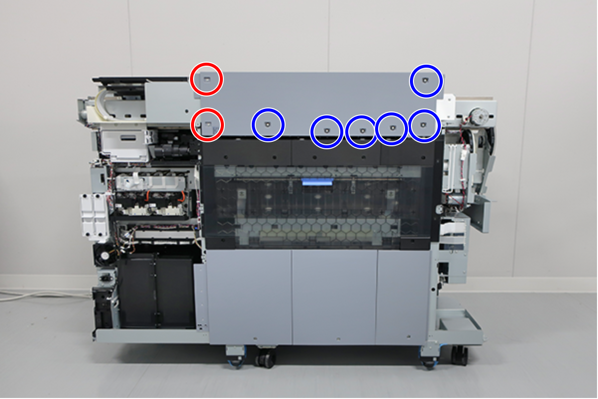
- : Silver M3x8 Cup S-tite screw
 : Silver M3x8 Cup S-tite screw with plastic washer
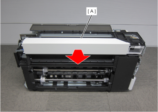
- Remove the Printer Cover Unit backward.
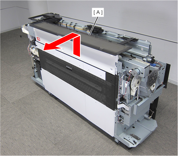
- Open the Printer Cover.
Remove the Home Side Top Cover (A).
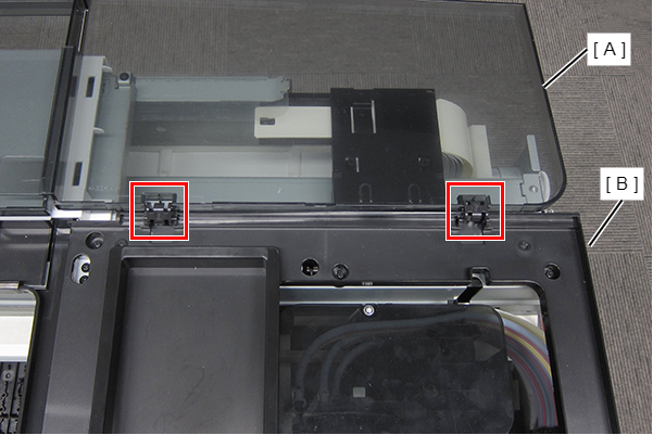
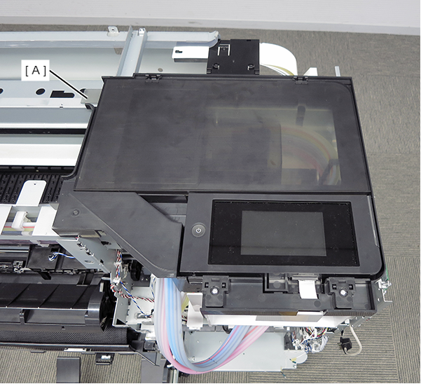 Assemble / 組み立て
Set the two hinges of the Home Side Top Cover (A) on the guides of the Panel Lower Cover (B).
- Remove the four screws and then remove the Panel Hinge Cover (A).
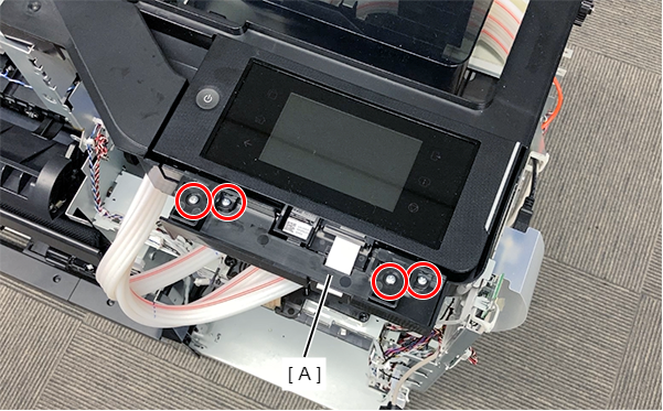
- : Silver M3x8 P-tite screw
 Lubrication / 注油
Before attaching the part, refer to the following and then lubricate.
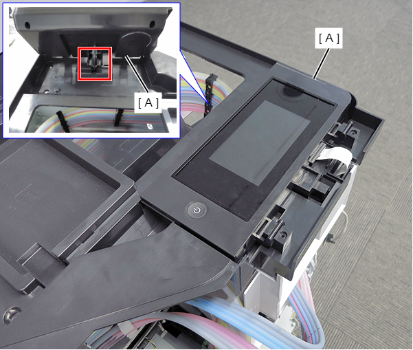
- Lift the Panel Assy (A), and release from the stopper.
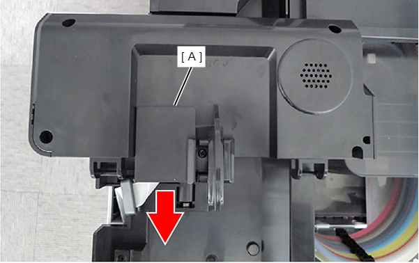
- Slide the FFC Cover (A) in the direction of the arrow to remove.
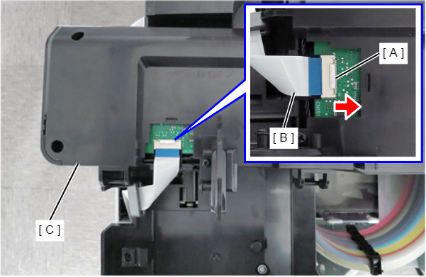
- With the connector metal part (A) pushed in the direction of the arrow, remove the FFC (B).
- Remove the Panel Assy (C).
- Open the Panel Hinge Cover.
- Remove the Printer Cover Right Unit (A).
- Remove the two screws.
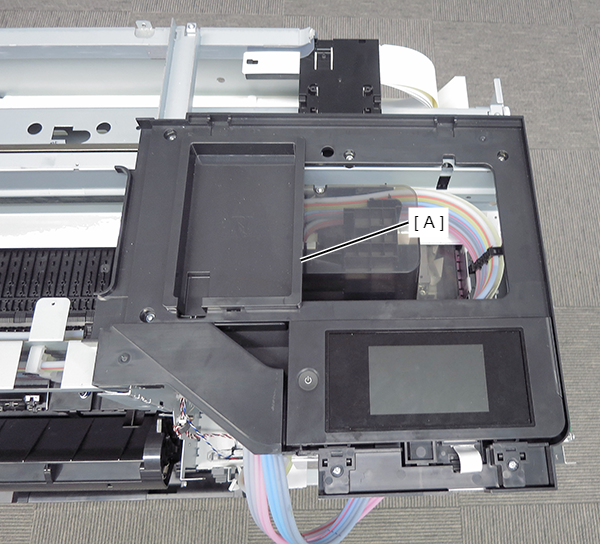
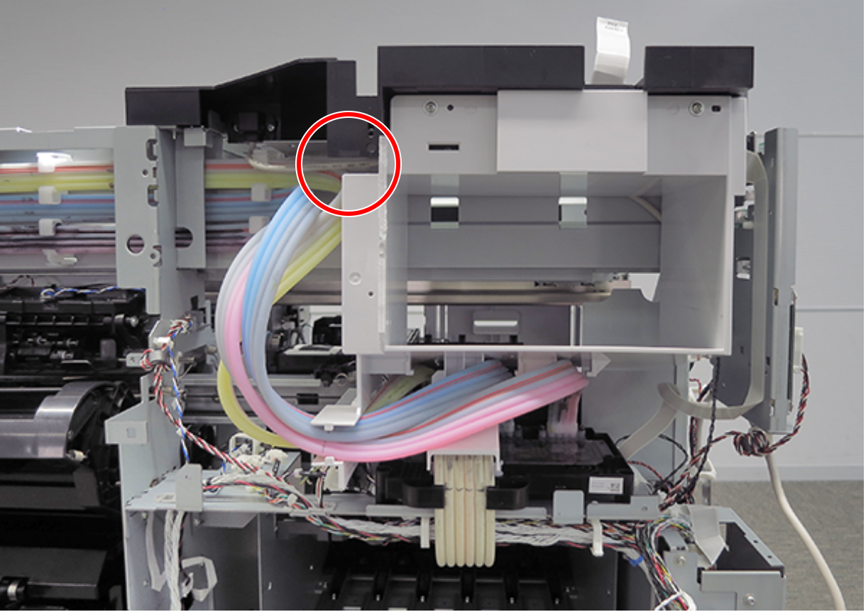
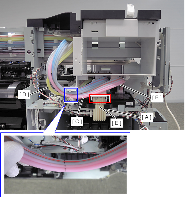
- Release the two ink tubes (B/C) from the two guides of the Head Maintenance Cover Front (A).
Release the three ink tubes (B/C/D) from the guide of the Head Maintenance Cover Front (A), and remove it.
- : Silver M3x10 Cup P-tite screw
Assembly / 組み立て- Be careful not to pinch the ink tube with the front of the head maintenance cover.
- There are two types of Head Maintenance Cover Front, and the assembly method differs depending on the shape.
- For shape A
- Route the ink tubes (A) of the Ink Bifurcated Flow Channel Unit through the guides.
- Put the marking portions (B/C/D) of the ink tubes in the guides.
- Align the marking of the ink tube (E) with top edge of the hook of the Ink Bifurcated Flow Channel Unit.
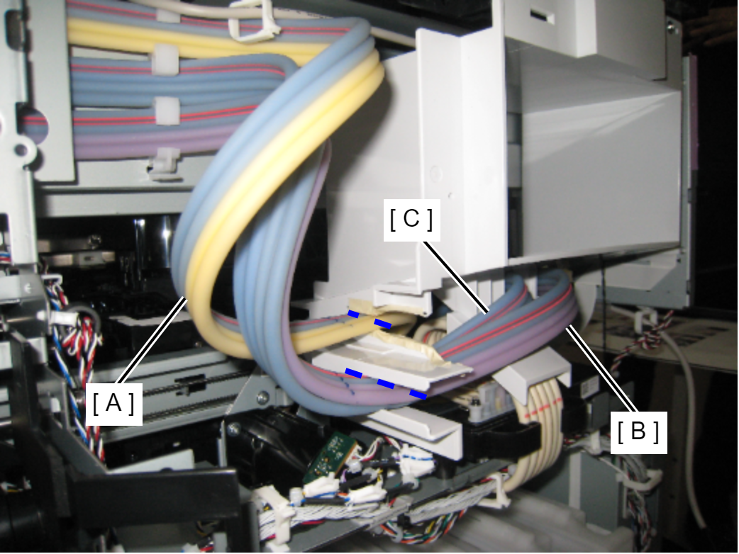
- For shape B
- Route the ink tubes of the Ink Bifurcated Flow Channel Unit through the guides.
- Place the ink tube (A) in the upper guide and the ink tube (B/C) in the lower guide.
- Align the marking of the ink tube with top edge of the hook of the Ink Bifurcated Flow Channel Unit.
- For shape A
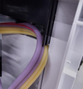
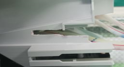
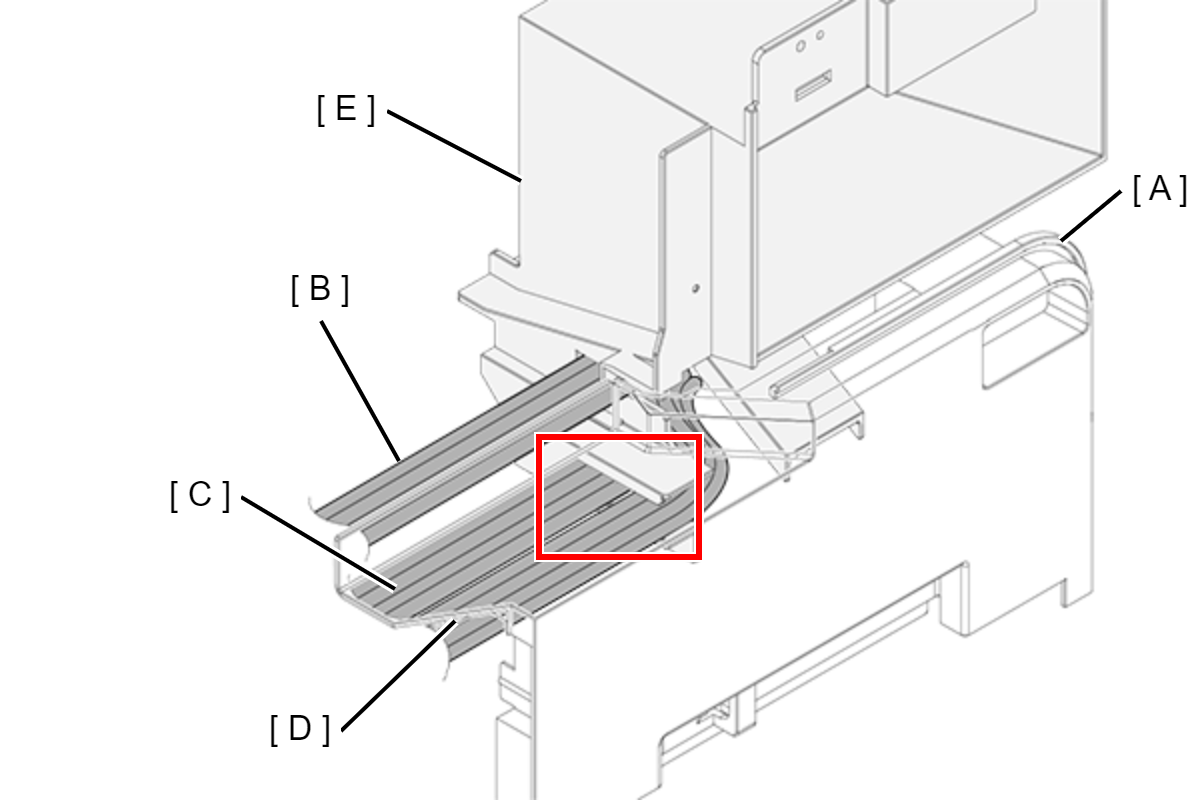
- Make sure that the Ink Tube (B) is not crushed when the Ink Holder Housing (A) is installed.
- Insert the Ink Tube (C) and Ink Tube (D) parallel to each other into the slit in the Head Maintenance Cover Front (E).
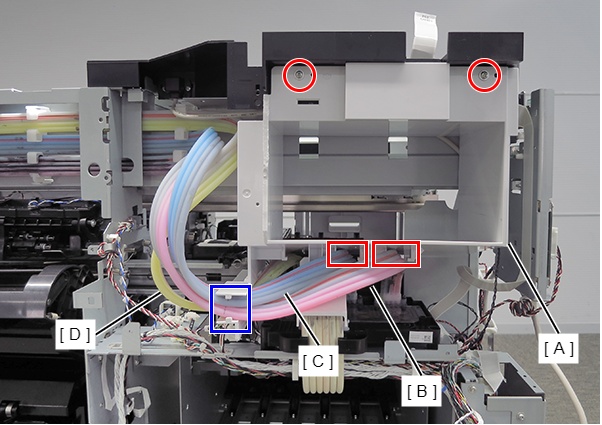
- Remove the two screws.
- Release the two ink tubes (B/C) from the two guides of the Head Maintenance Cover Front (A).
Release the three ink tubes (B/C/D) from the guide of the Head Maintenance Cover Front (A), and remove it.
- : Silver M3x10 Cup P-tite screw
Assembly / 組み立て- Be careful not to pinch the ink tube with the front of the head maintenance cover.
- There are two types of Head Maintenance Cover Front, and the assembly method differs depending on the shape.
- For shape A
- Route the ink tubes (A) of the Ink Bifurcated Flow Channel Unit through the guides.
- Put the marking portions (B/C/D) of the ink tubes in the guides.
- Align the marking of the ink tube (E) with top edge of the hook of the Ink Bifurcated Flow Channel Unit.
- For shape B
- Route the ink tubes of the Ink Bifurcated Flow Channel Unit through the guides.
- Place the ink tube (A) in the upper guide and the ink tube (B/C) in the lower guide.
- Align the marking of the ink tube with top edge of the hook of the Ink Bifurcated Flow Channel Unit.
- For shape A
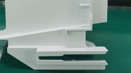
- Make sure that the Ink Tube (B) is not crushed when the Ink Holder Housing (A) is installed.
- Insert the Ink Tube (C) and Ink Tube (D) parallel to each other into the slit in the Head Maintenance Cover Front (E).
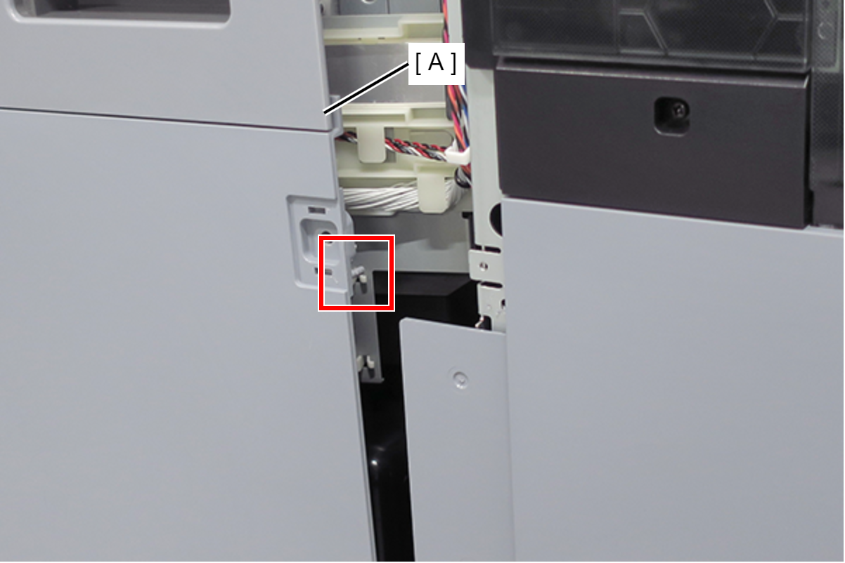
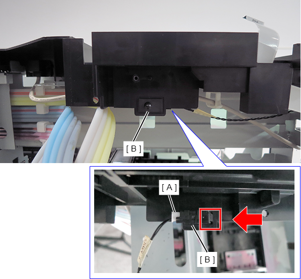
- Remove the cable (A) from the connector.
- Press the hook on the rear side in the direction of the arrow to release.
- Pull out the Head Maintenance Cover Front Cover Sensor (B) to the front to remove.
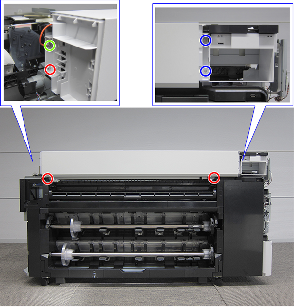
- Remove the two screws (red).
- Remove the two screws (blue), and remove the USB cable (A).
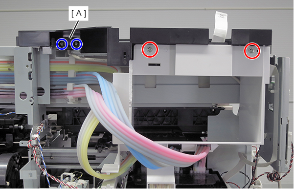
- : Silver M3x10 Cup P-tite screw
- : Silver M3x8 P-tite screw
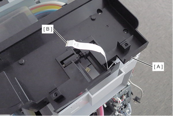
- Remove the ferrite core (B) from the FFC (A).
- Remove the six screws.
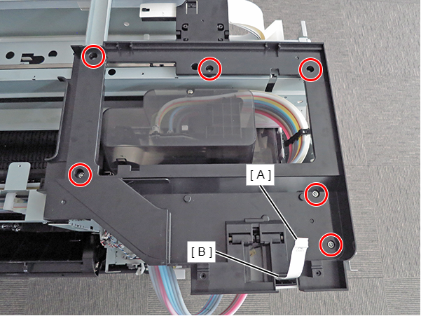
- : Silver M3x8 Cup S-tite screw
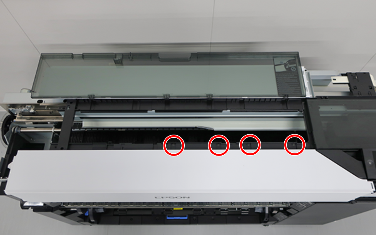
Release the FFC (B) from the Panel Lower Cover (A), and remove the Panel Lower Cover (A).
 Lubrication / 注油
Before attaching the part, refer to the following and then lubricate.
| Lubrication / 注油 |
Before attaching the part, refer to the following and then lubricate. |