CIS Module Full Side
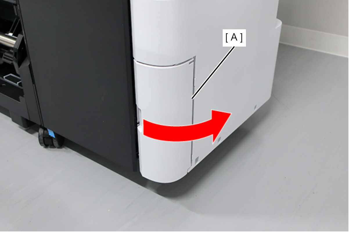
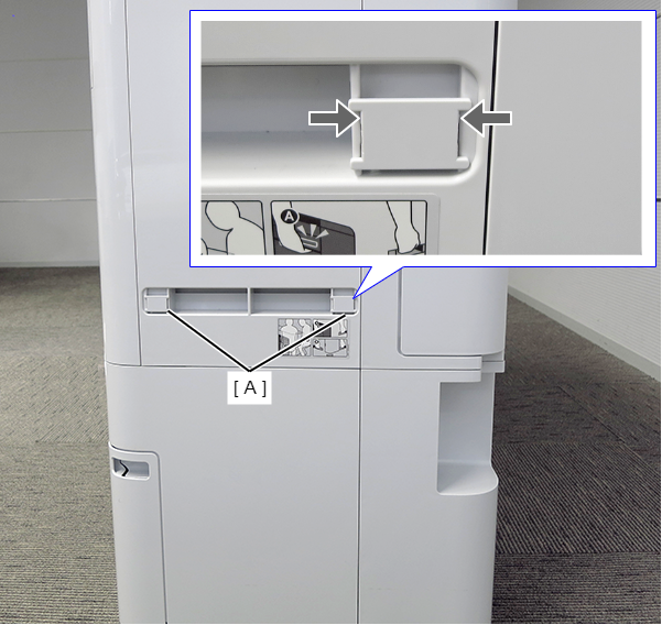
- Open the Maintenance Box Cover (A).
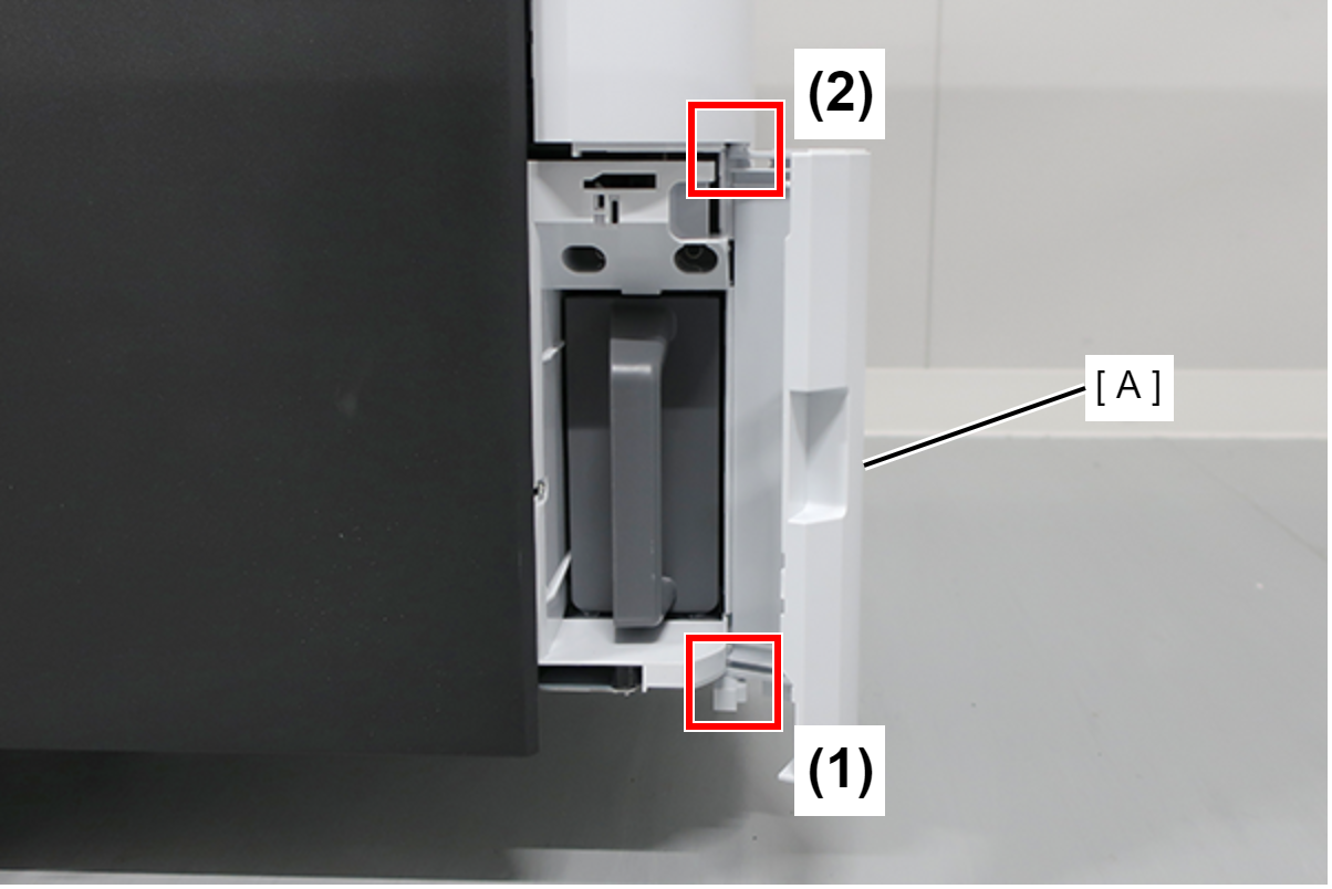
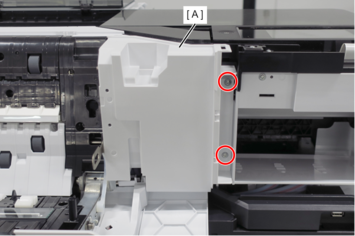
- Release the 2 tabs of the Maintenance Box Cover (A) in the order shown in the figure below, and remove.
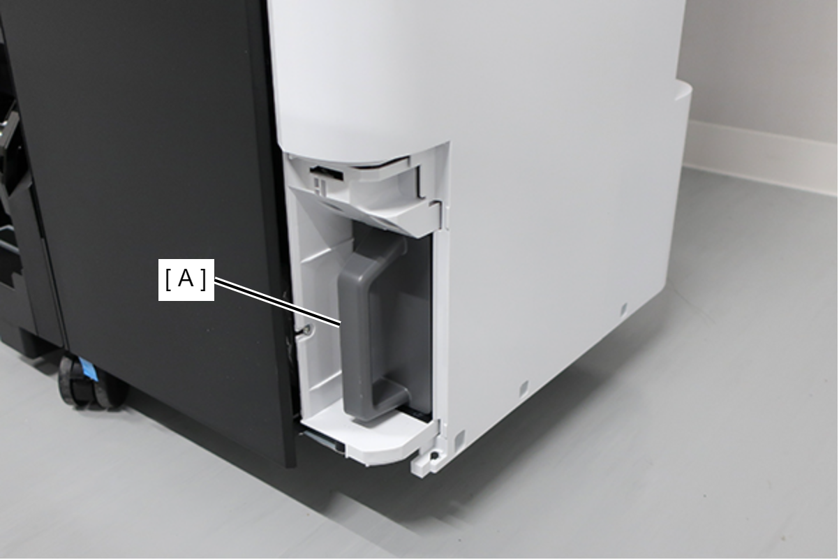
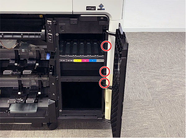
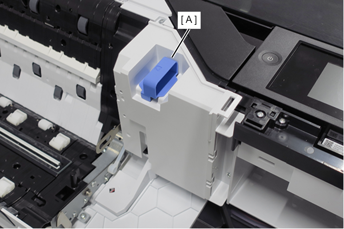
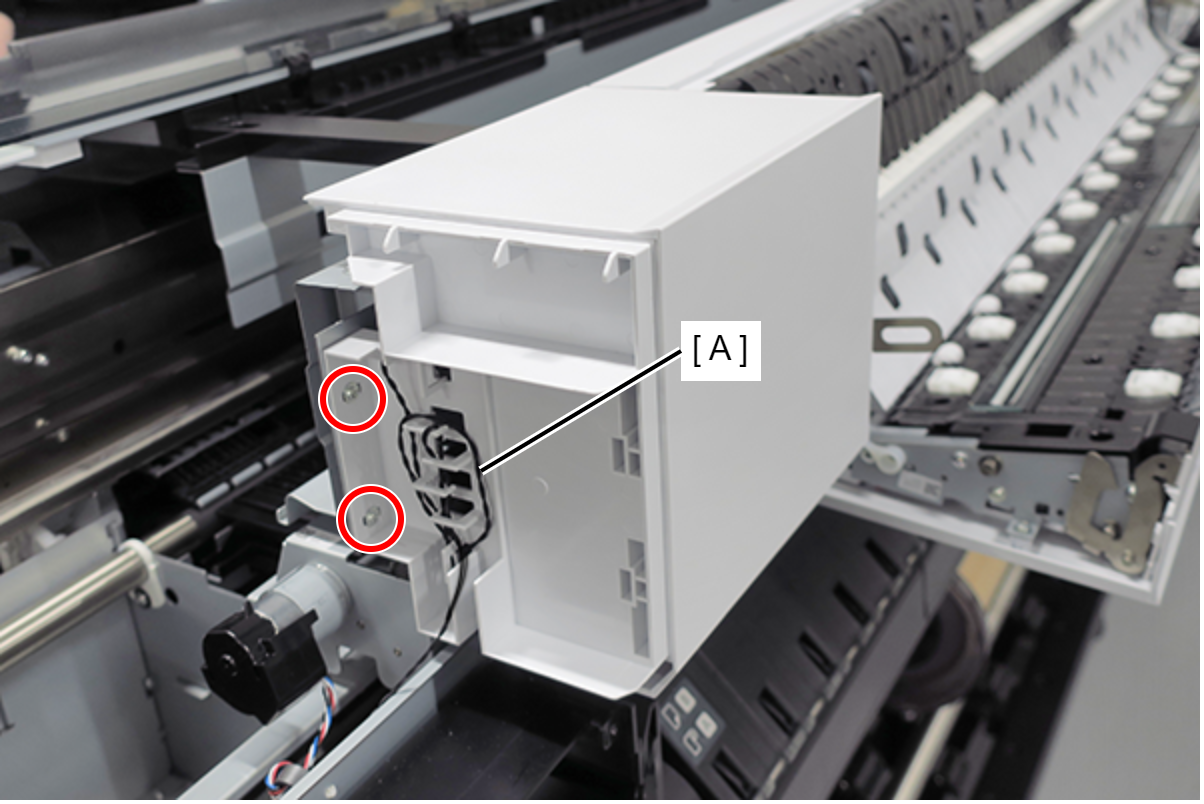
- Remove the Maintenance Box (A).
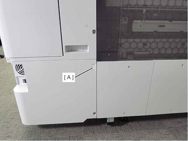
- Remove the screw.
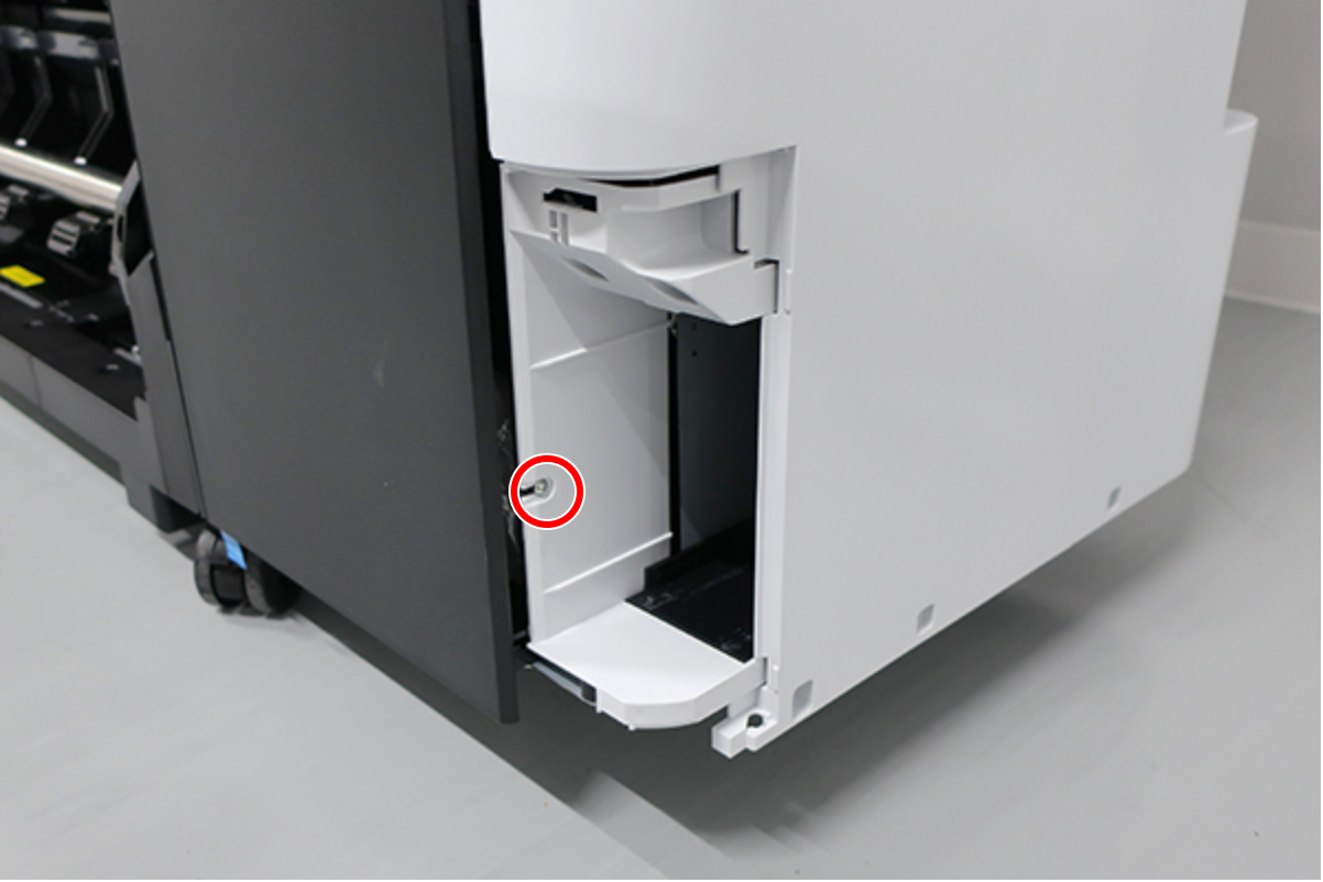
 : : Silver M3x8 Cup S-tite screw
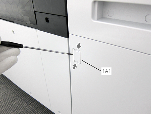
- Insert a flathead screwdriver and release the 2 hooks each, and remove the two screw cover (A).
- Insert a flathead screwdriver and release the 2 hooks, and remove the screw cover (A).
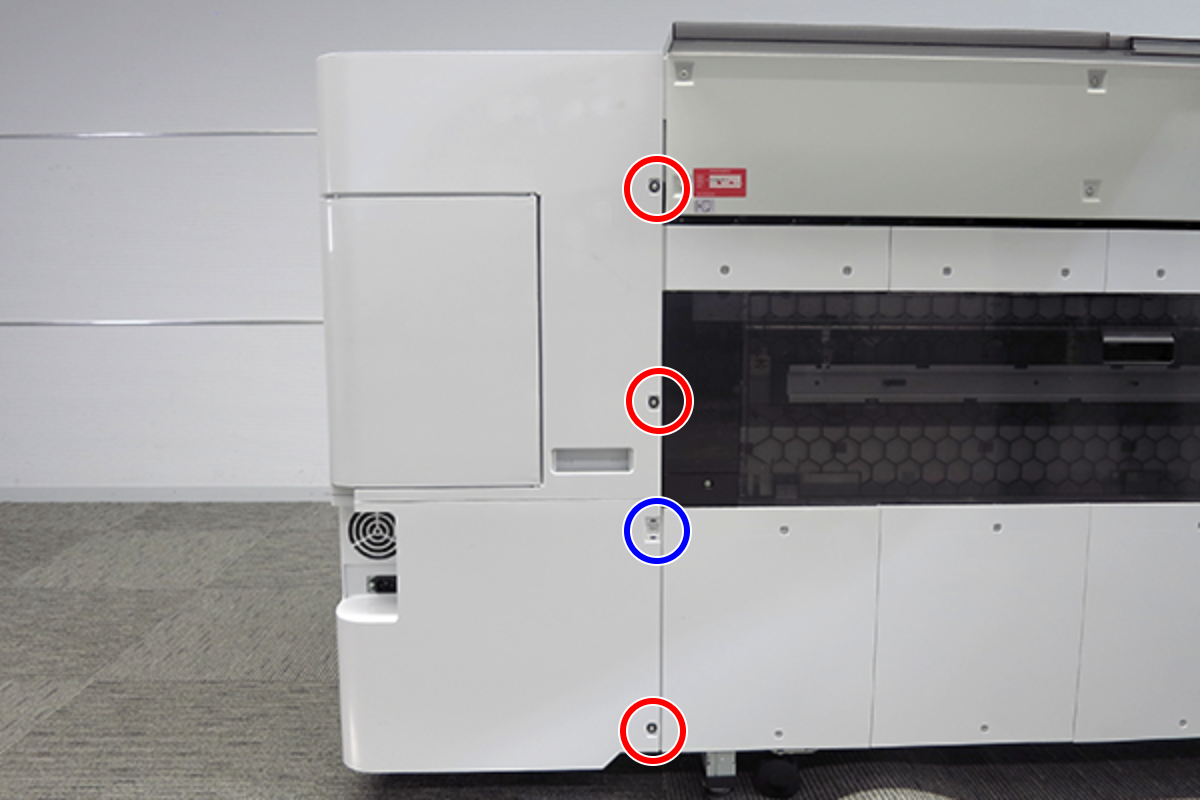
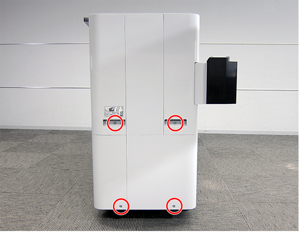
- Remove the three screws at the front side.
- : Black M3x8 Cup P-tite screw
- Remove the five screws at the right side.
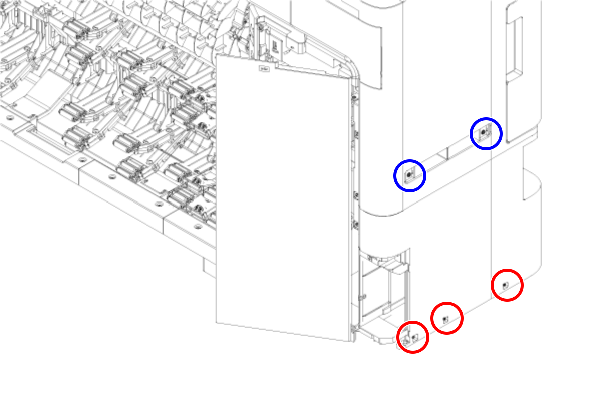
- : Silver M3x8 Cup S-tite screw
 : Silver/M4x8/machine screw
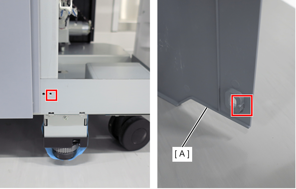
- Remove the four screws at the rear side.
- : Silver M3x8 Cup S-tite screw with plastic washer
- : : Silver M3x8 Cup S-tite screw
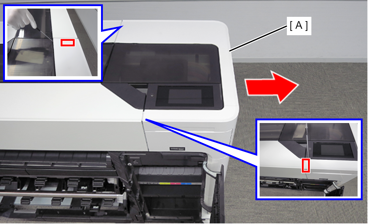
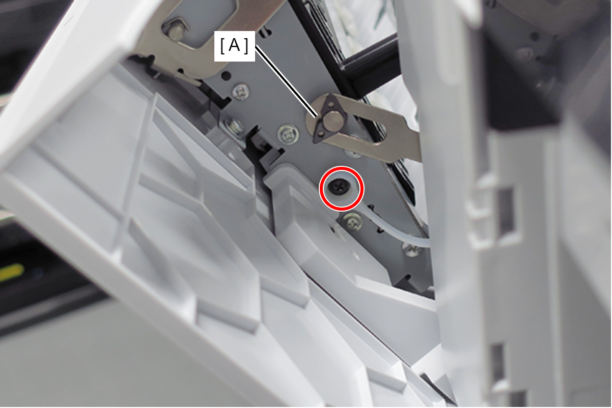
- On the printer rear side, release the dowel of the Home Side Cover Unit (A).
- Insert a flathead screwdriver and release the 2 tabs each, and remove the Home Side Cover Unit (A) in the direction of the arrow.
- Insert a flathead screwdriver and release the two hooks, and remove the screw cover (A).
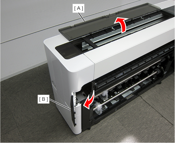
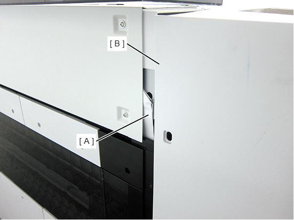
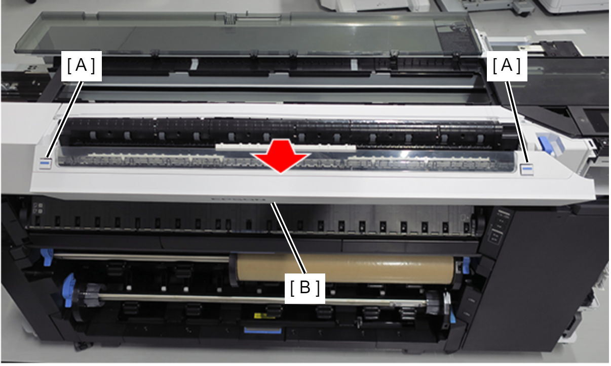
- Open the Printer Cover (A) and the Cutter Cover (B).
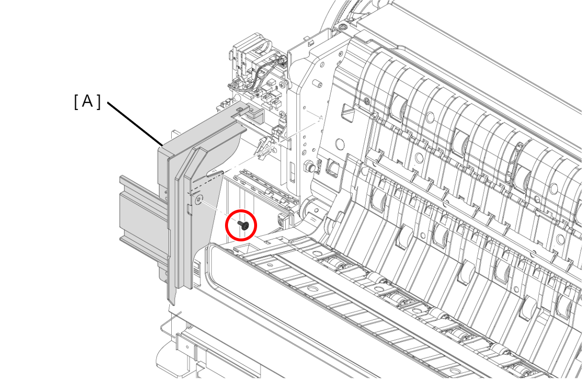
- Remove the three screws at the front side.
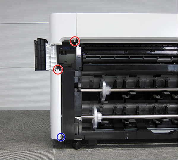
- : Silver M3x10 Cup P-tite screw
- : : Silver M3x8 Cup S-tite screw
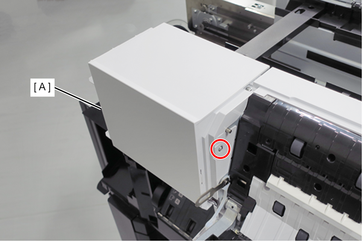
- Remove the screw at the top side.
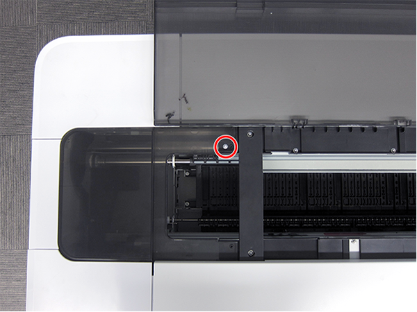
- : : Silver M3x8 Cup S-tite screw
- Remove the four screws at the rear side.
- : Silver M3x8 Cup S-tite screw with plastic washer
- : : Silver M3x8 Cup S-tite screw
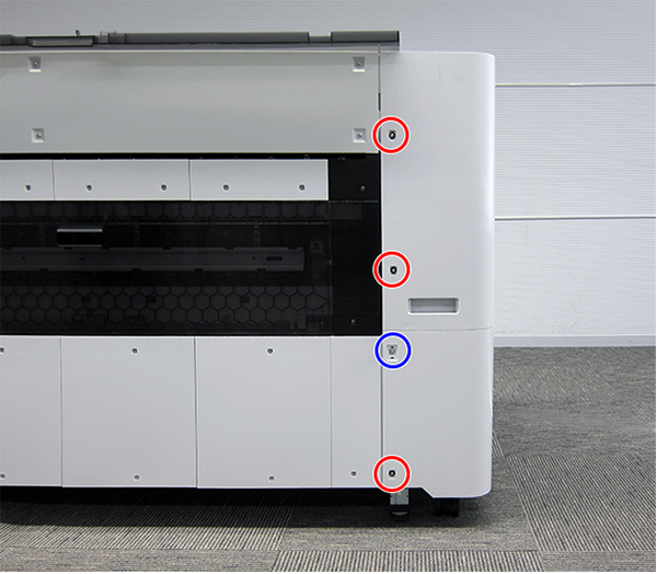
- Remove the four screws at the left side.
- : Silver M3x8 Cup S-tite screw
- : Silver/M4x8/machine screw
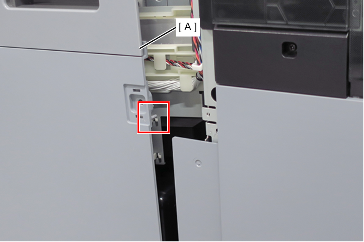
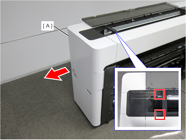
On the printer rear side, release the dowel of the Full Side Cover Unit (A).
Remove the Full Side Cover Unit (A) from the dowels, and remove it while it in the direction of the arrow.
 Assemble / 組み立て
When installing the Full Side Cover Unit (B), carefully the Head FFC (A) so that it does not damage.
- Remove the Button (A). (Only perform for SC-P8500DM series/SC-T7700DM series/SC-T5700DM series)
- Remove the two screws, and then remove the Scanner Home Side Cover (A). (Only perform for SC-P8500DM series/SC-T7700DM series/SC-T5700DM series)
- : Silver M3x8 Cup P-tite screw
- Push two buttons (A), and open the Scanner Unit (B). (Only perform for SC-P8500DM series/SC-T7700DM series/SC-T5700DM series)
- Remove the screw on the printer home side. (Only perform for SC-P8500DM series/SC-T7700DM series/SC-T5700DM series)
- Remove the C Shape Washer (A). (Only perform for SC-P8500DM series/SC-T7700DM series/SC-T5700DM series)
- : Black M3x4 Cup Step type S-tite screw
- Remove the Fixing Slider (A) from shaft. (Only perform for SC-P8500DM series/SC-T7700DM series/SC-T5700DM series)
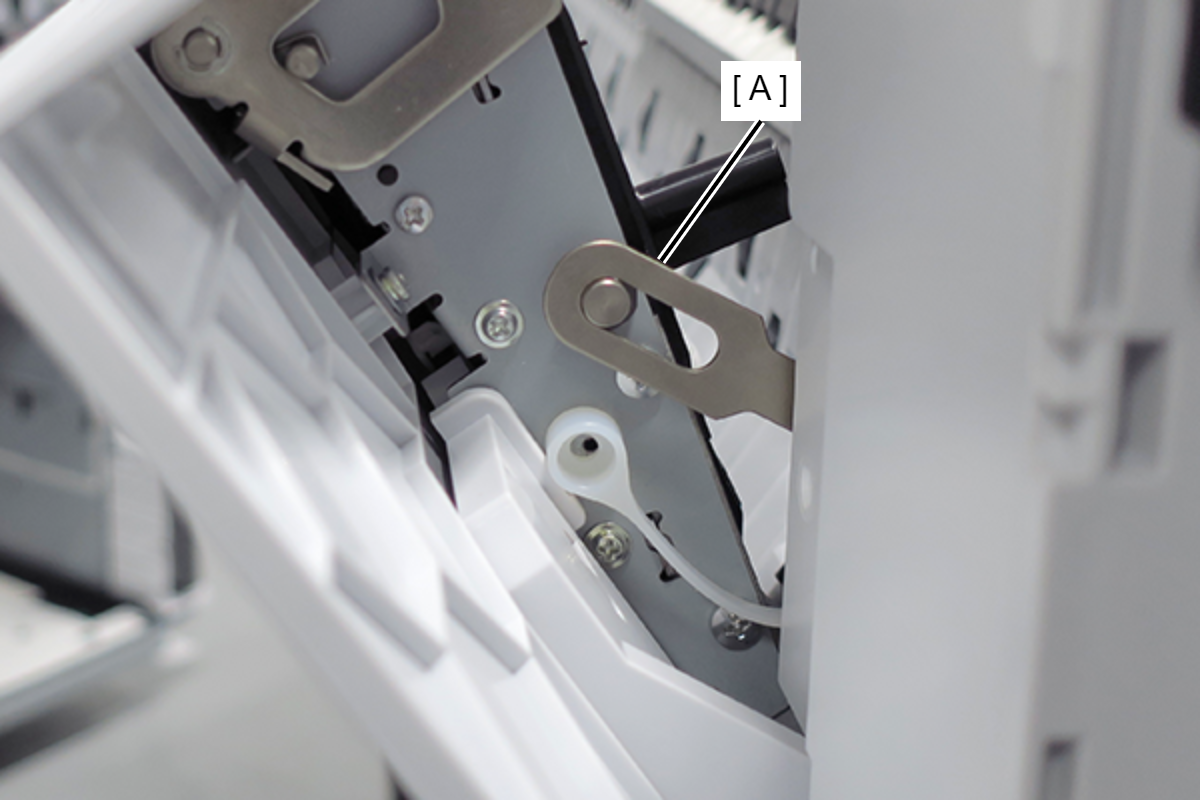
- Remove the screw on the printer full side. (Only perform for SC-P8500DM series/SC-T7700DM series/SC-T5700DM series)
- Remove the C Shape Washer (A). (Only perform for SC-P8500DM series/SC-T7700DM series/SC-T5700DM series)
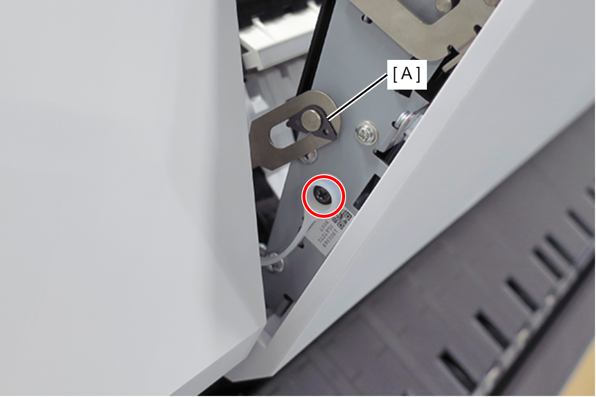
- : Black M3x4 Cup Step type S-tite screw
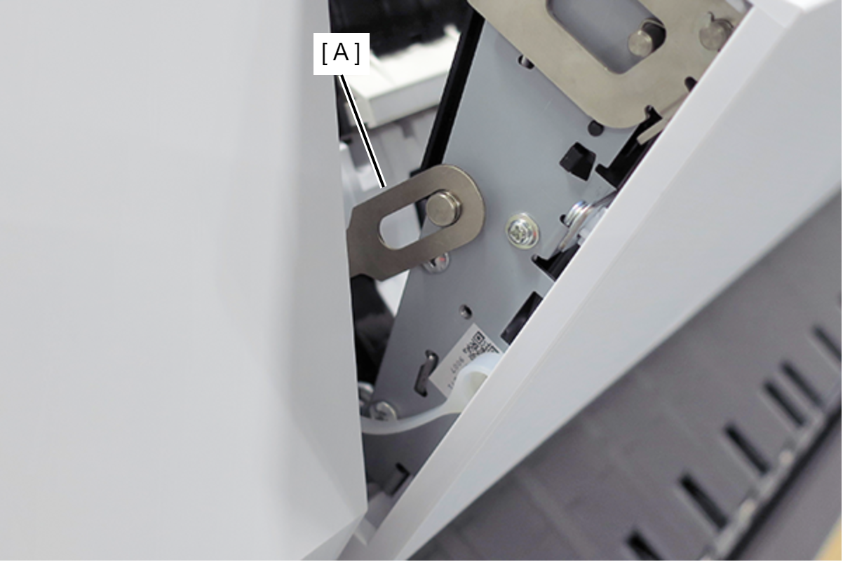
- Remove the Fixing Slider (A) from shaft. (Only perform for SC-P8500DM series/SC-T7700DM series/SC-T5700DM series)
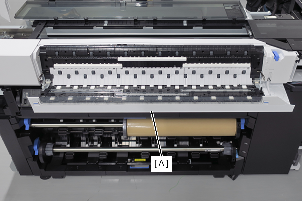
- Open the Scanner Unit (A). (Only perform for SC-P8500DM series/SC-T7700DM series/SC-T5700DM series)
- Release the sensor cable (A). (Only perform for SC-P8500DL series/SC-T7700DL series)
- Remove the two screws. (Only perform for SC-P8500DL series/SC-T7700DL series)
- : Silver M3x8 Cup S-tite screw
- Remove the screw, and then remove the Scanner Full Side Front Cover (A). (Only perform for SC-P8500DM series/SC-T7700DM series/SC-T5700DM series)
- : Silver M3x8 Cup S-tite screw
 Check Point / チェックポイント
- Scanner Full Side Front Cover of SC-T5700DM series
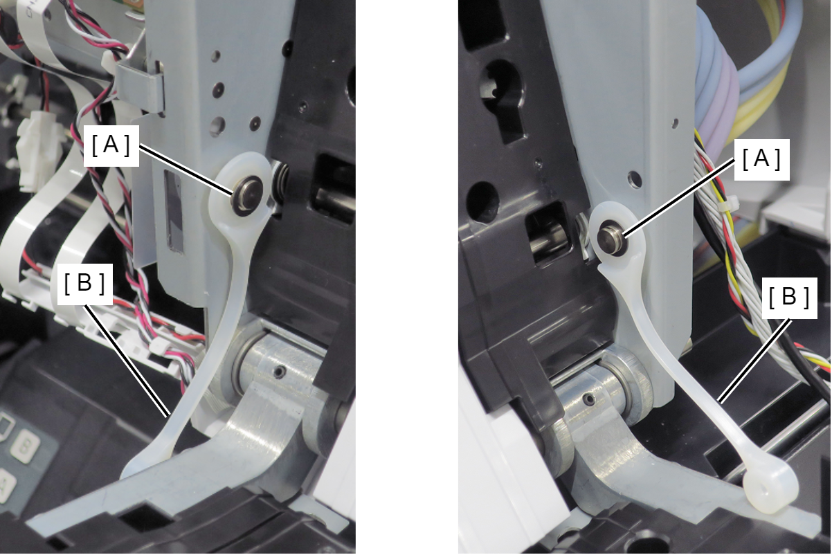
- Remove the C Shape Washer (A) and the Fixing Slider (B). (Only perform for SC-P8500DM series/SC-T7700DM series/SC-T5700DM series)
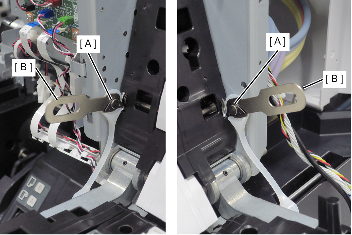
- Remove the Washer (A) and the Strap (B). (Only perform for SC-P8500DM series/SC-T7700DM series/SC-T5700DM series)
- Remove the four screws. (Only perform for SC-P8500DM series/SC-T7700DM series/SC-T5700DM series)
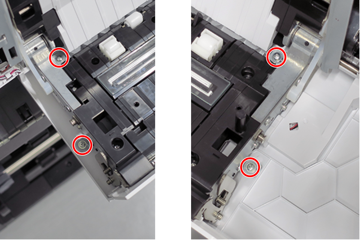
- :Silver M3x8 P-tite screw with built-in washer
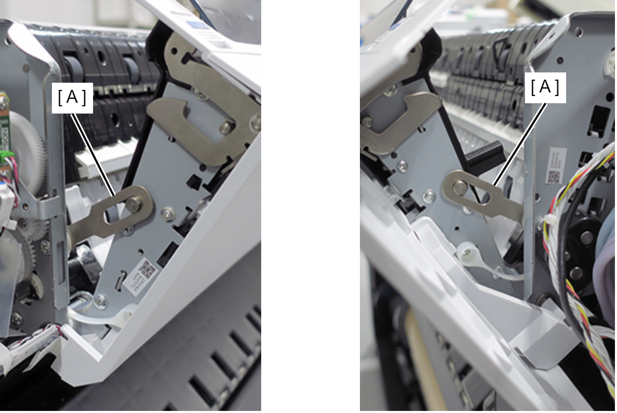
- Hang each of the two fixing sliders (A) on the shaft. (Only perform for SC-P8500DM series/SC-T7700DM series/SC-T5700DM series)
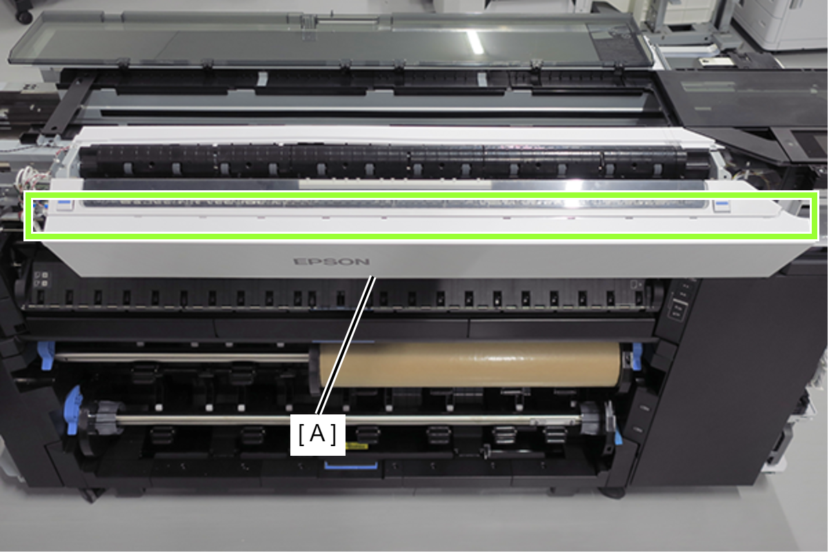
Release the 10 hooks and remove the Scanner Front Cover (A). (Only perform for SC-P8500DM series/SC-T7700DM series/SC-T5700DM series)
 Assembly / 組み立て
- Install the Scanner Front Cover (A) while engaging its 10 hooks (B) and 13 tabs (C) with the positioning points on the scanner.
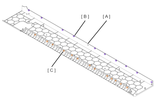
- Install the Scanner Front Cover (A) while engaging its 10 hooks (B) and 13 tabs (C) with the positioning points on the scanner.
- Remove the three screws, and then remove the Scanner Front Top Cover (A). (Only perform for SC-P8500DM series/SC-T7700DM series/SC-T5700DM series)
- : Silver M3x6 Cup S-tite screw
Assembly / 組み立て- Install the Scanner Front Top Cover (A) while inserting its three dowels into the positioning holes in the scanner.
- Remove the two screws and remove the Center Front Guide B (A).
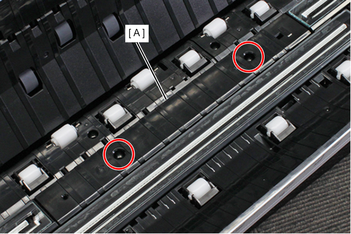
- : Silver M3x6 Bind S-tite screw
- Remove the two screws and remove the Left Edge Front Guide (A).
- : Silver M3x6 Bind S-tite screw
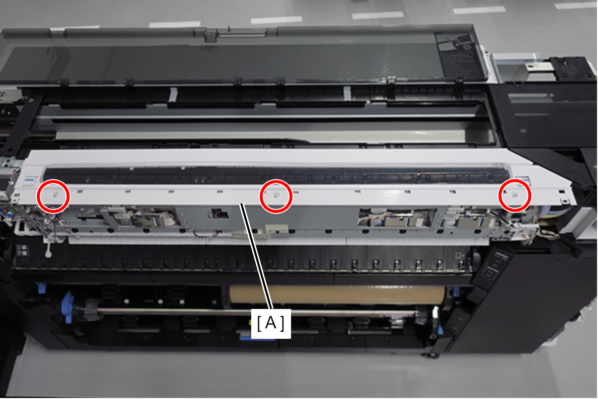
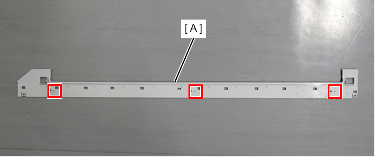
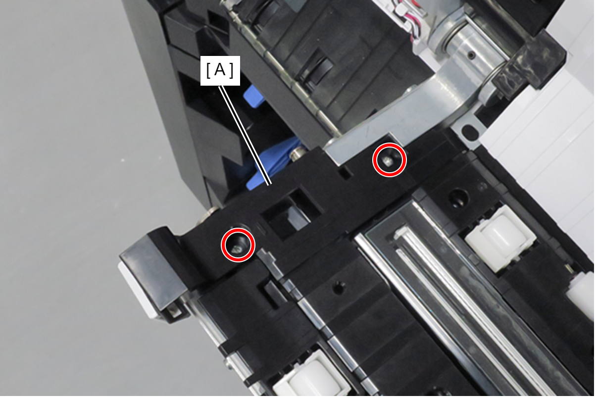
- Remove the two screws, lift up the CIS Module Full Side (A), and turn over.
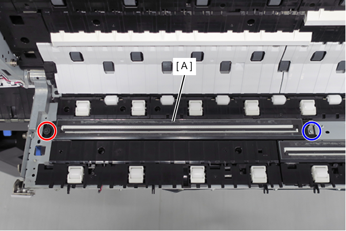
- : Black M3x4.9 screw with rubber
- : Silver M3x8 Cup S-tite screw
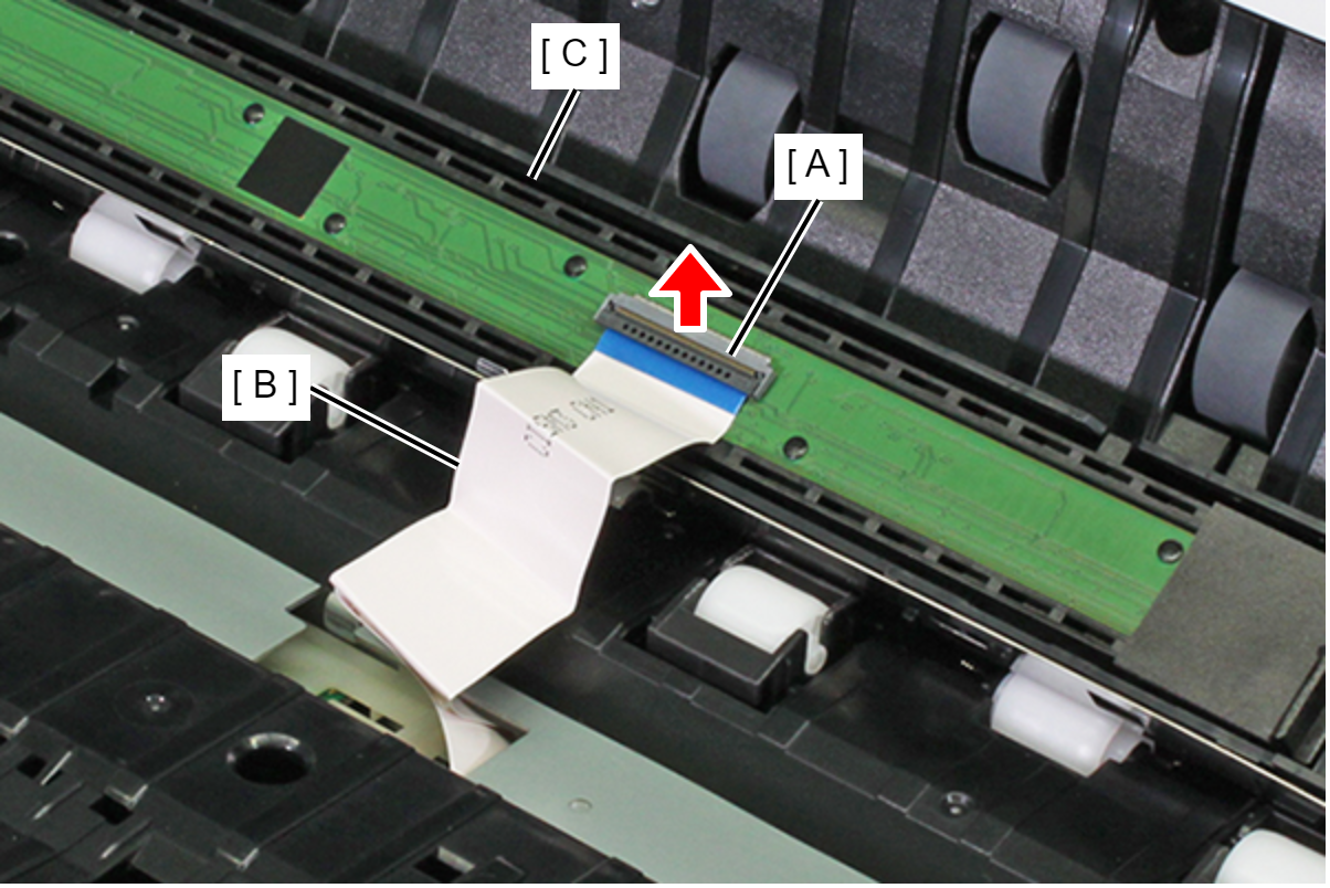
Lift the connector lock (A), remove the CIS Module Full Side FFC (B) from the CIS Module Full Side connector, and remove the CIS Module Full Side (C).
 Assembly / 組み立て
- Be careful not to touch the CIS Module glass.
- When connecting the CIS Module Full Side FFC, secure firmly using the connector lock.
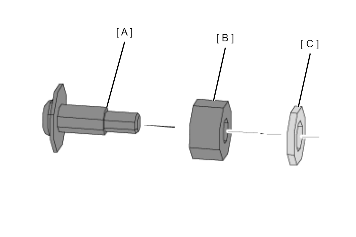
- Screw A (A) which secures the CIS Module Full Side is tightened together with the spacer (B) and the washer (C). When securing screw A (A), fit the spacer (B) and the washer (C) in the order as shown in the diagram below.
 Adjustment / 調整 Adjustment / 調整 |
When removing/replacing this part, refer to following page and make sure to perform the specified operations including required adjustment. |