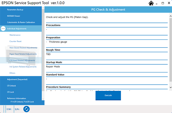
PG Check & Adjustment
Required Tools
Feeler Gauge
Estimate Time
Approx. 10 min.
Startup Mode
Repair mode
Standard Values
1.20 mm (1.15 mm passing, 1.25 mm stopped)
Step
Check
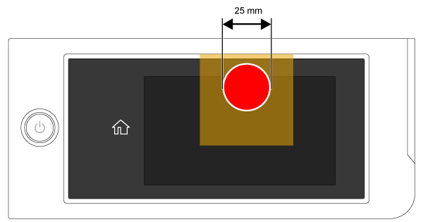
- Start the printer in repair mode. Turn the power on while touching [Screen Center], and keep pressing until the mode select screen is displayed. Touch the center of the panel to start repair mode.
- If media is loaded, remove it.
- Start the Service Program, and select PG Check& Adjustment.
Check the standard value range on the screen.
 Caution / 注意
Must be execute from the service program to ensure correct adjustment.
Do not reach inside the printer during operation when the printer cover is removed and the cover sensor is activated.Click the [Run] button.
 Check Point / チェックポイント
When click [Execute], the printer executes the following sequence.
Auto Platen Gap (APG) sets CR vertical position to '-' for PG adjustment.
After that, the CR lock is un-locked.
CR unit moves to full side.Caution / 注意Ensure that the AC cable is removed before performing the following work.
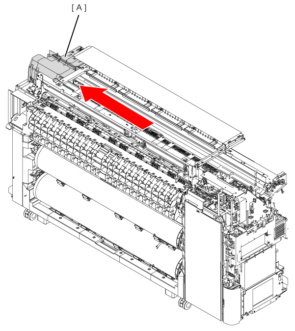
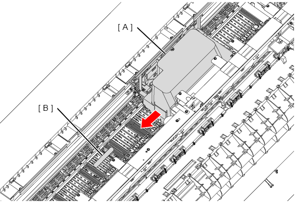
Open the Printer Cover.
- Move the CR Unit (A) to the Full side.
Count the PG measurement positions based on the nip release roller (A) on the home side.
Printer width PG measurement position (position counted from home side nip release roller #1) 44 inches 8th 36 inches 6th 24 inches 4th 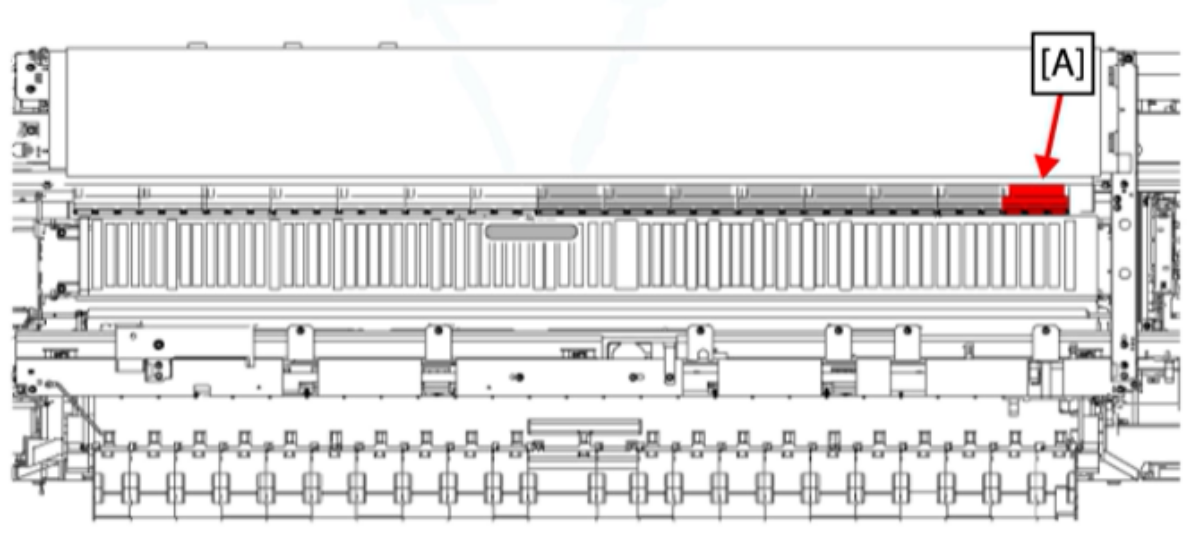
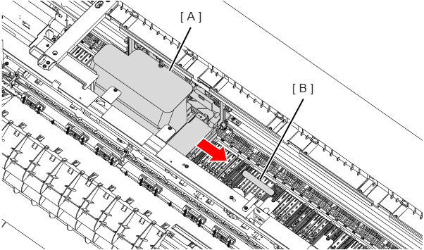
- Put the 1.15 mm clearance gauge (B) to the PG measurement position on the platen in front of the corresponding nip release roller.
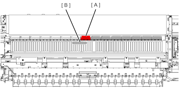
- Move the CR Unit (A) slowly toward the home side and check that the gauge (B) does not come in contact with the Print Head (C).
 Caution / 注意
Ensure that the CR Unit is moved slowly, and if the Feeler Gauge contacts the Print Head, do not move the CR Unit any more.
- Remove the gauge.
- Move the CR Unit to the Full side.
- Put a 1.25 mm thickness gauge.
- Move the CR Unit slowly toward the home side and check that the gauge comes in contact with the Print Head.
- Use these results to check if PG is at the standard value at the Home side. (1.15 mm: no contact / 1.25 mm: contact)
- Remove the gauge.
- Move the CR Unit to the Home side.
- Put the 1.15 mm clearance gauge (B) to the PG measurement position on the platen in front of the corresponding nip release roller.
- Slowly move the CR Unit (A) towards the Full side, and check if the Print Head is contacting the gauge (B).
 Caution / 注意
Ensure that the CR Unit is moved slowly, and if the Feeler Gauge contacts the Print Head, do not move the CR Unit any more.
- Remove the gauge.
- Move the CR Unit to the Home side.
- Put a 1.25 mm thickness gauge.
- Move the CR Unit slowly toward the Full side and check that the gauge comes in contact with the Print Head.
- Use these results to check if PG is at the standard value at the Full side. (1.15 mm: no contact / 1.25 mm: contact)
- If the PG is within the standard values for both the Home side and the Full side, then confirmation is complete. If either is outside the PG values, then go to "Adjustment" section.
Adjustment
- Ensure the following parts are removed.
- Access the printer information getting website using the following link:
https://support2.epson.net/scp120kos/ - Enter the serial number of the printer and the password (7777) in the website.
- Click the [Save] button to save the displayed offset values as a csv file.
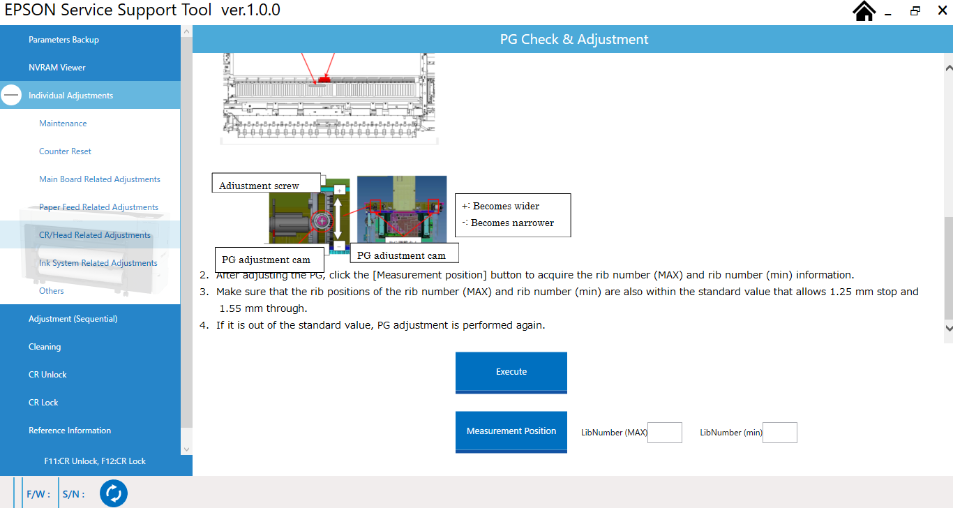
- Click [Measurement Position].
- Select the saved serial#_OFFSET.csv file and click the [Open] button.
- Value information of rib number (MAX)*1 and rib number (min)*2 is displayed.
*1: Rib number (MAX) means the highest point of platen height.
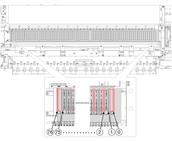
*2: Rib number (min) means the lowest height of the platen. There is a certain number of platen ribs for each width of the printer size. Please refer to the table <How to count the rib number> for the rib position of the width of each printer.
Printer width Rib Position 44 inches 76 36 inches 61 24 inches 42 Check Point / チェックポイントFor a 44-inch printer, there are 77 rib positions.
The first rib is on the home side of the printer and counts as Rib #0.
The next rib on the left side is rib #1 and continues to rib #76, which is located on the full side of the printer platen.- Check the platen gap below at both the maximum and minimum rib positions displayed on the screen.
- Rib number (MAX) 1.00 mm: No contact
- Rib number (min) 1.40 mm: Contact
- Loosen the PG Adjustment Cam (A) for the side that is outside standard values.
- Move the PG Adjustment Cam referring to the following standards.
- Move the cam to the printer rear side: PG becomes wider.
- Move the cam to the printer front side: PG becomes narrower.
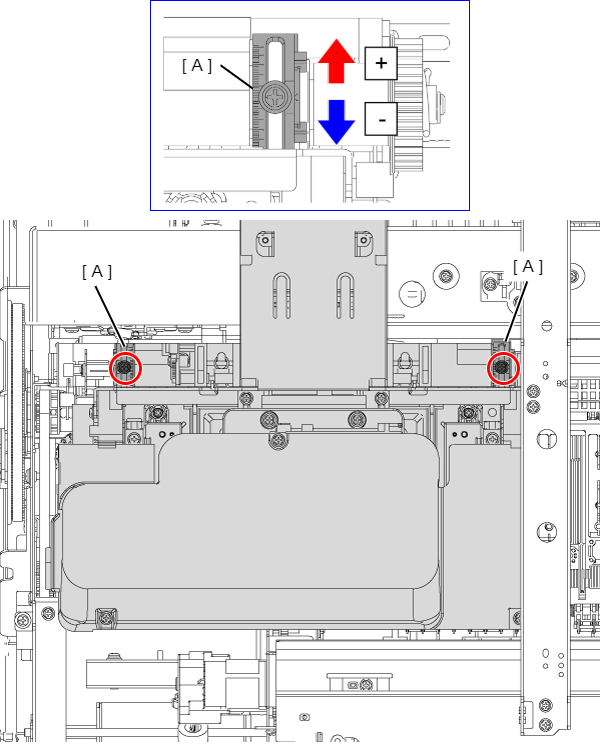 Check Point / チェックポイント
Moving the PG Adjustment Cam 1 notch changes the PG by 0.055 mm.
- Tighten the PG Adjustment Cam screw.
- Check, and confirm that the PG is at the standard value.
- Start the printer in repair mode.
- Start the Service Program, and select PG Check& Adjustment.
- Click [Measurement Position].
- Check again at the position of the displayed rib number, and confirm that the PG is at the standard value described below.
Repeat adjustment and confirmation of results until adjustment is complete.
 Check Point / チェックポイント
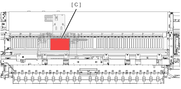
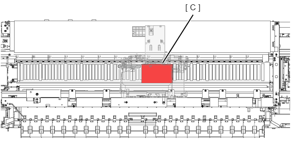
<How to count the rib number>
For the rib number, the eadge on the platen shown in the red frame is counted as 1 from the Home side. The maximum number is 76 at 44 inches at the Full side. The Full side is 44 inches and the maximum is 76th.