White Base Assy Full Side
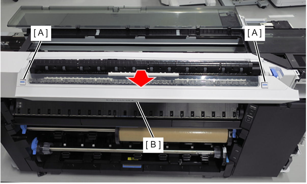
- Push two buttons (A), and open the Scanner Unit (B). (Only perform for SC-P8500DM series/SC-T7700DM series/SC-T5700DM series)
- Remove the screw on the printer home side. (Only perform for SC-P8500DM series/SC-T7700DM series/SC-T5700DM series)
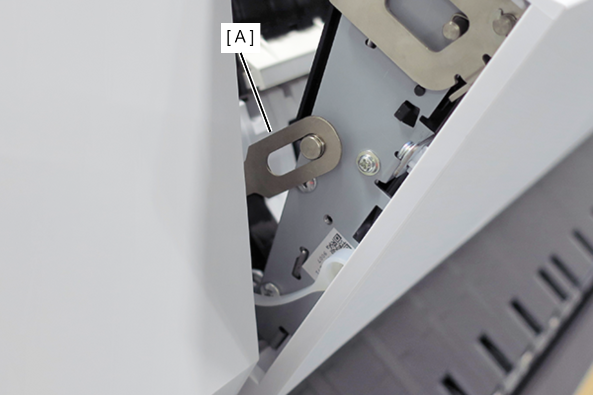
- Remove the C Shape Washer (A). (Only perform for SC-P8500DM series/SC-T7700DM series/SC-T5700DM series)
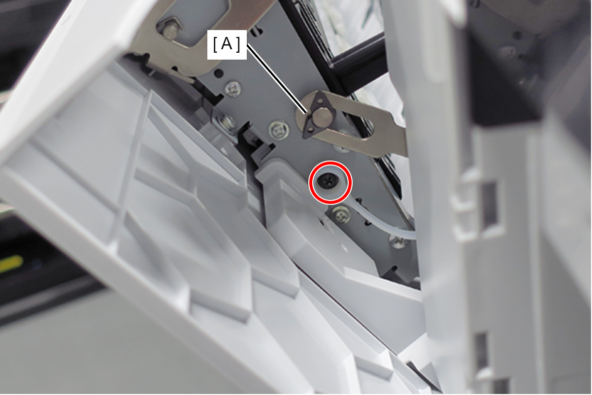
 : Black M3x4 Cup Step type S-tite screw
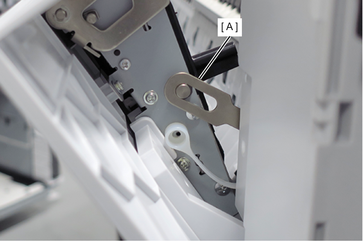
- Remove the Fixing Slider (A) from shaft. (Only perform for SC-P8500DM series/SC-T7700DM series/SC-T5700DM series)
- Remove the screw on the printer full side. (Only perform for SC-P8500DM series/SC-T7700DM series/SC-T5700DM series)
- Remove the C Shape Washer (A). (Only perform for SC-P8500DM series/SC-T7700DM series/SC-T5700DM series)
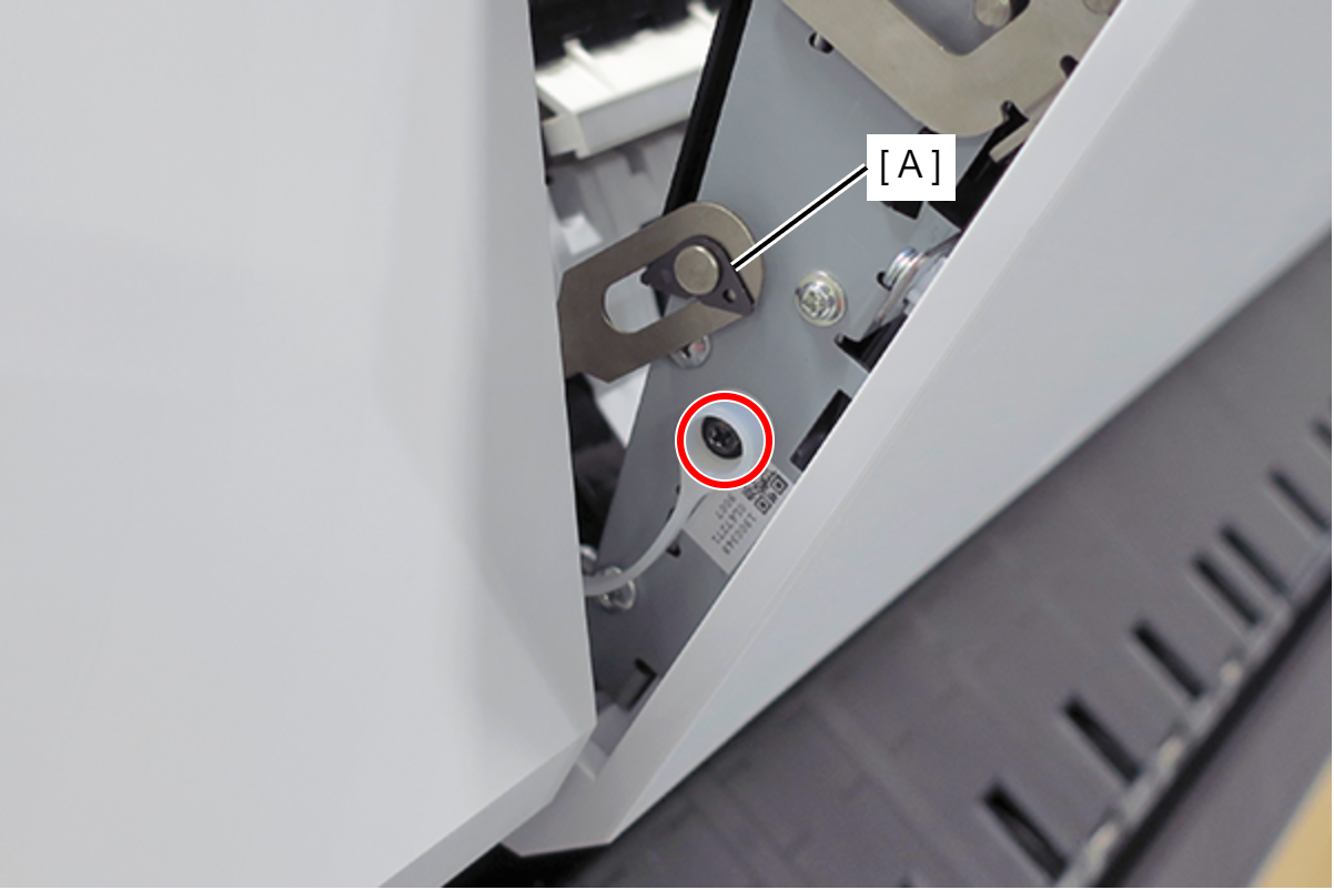
- : Black M3x4 Cup Step type S-tite screw
- Remove the Fixing Slider (A) from shaft. (Only perform for SC-P8500DM series/SC-T7700DM series/SC-T5700DM series)
- Open the Scanner Unit (A). (Only perform for SC-P8500DM series/SC-T7700DM series/SC-T5700DM series)
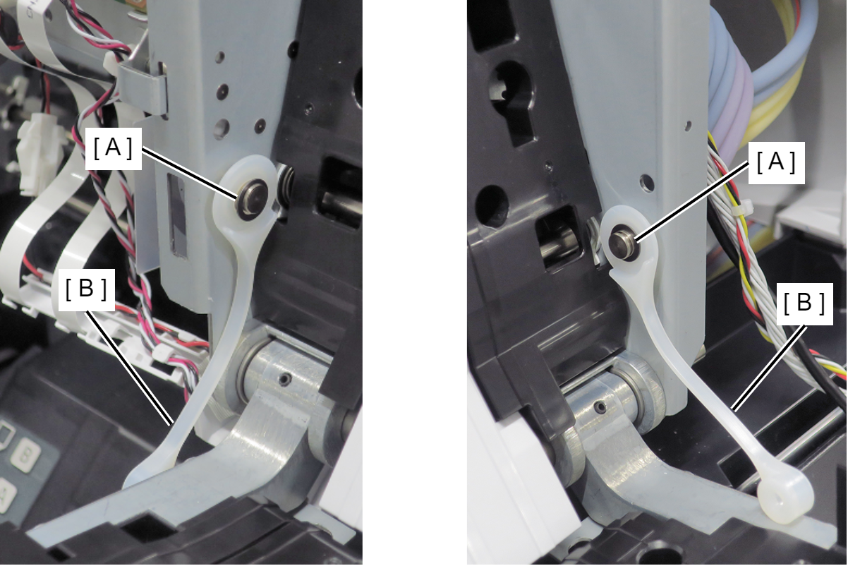
- Remove the C Shape Washer (A) and the Fixing Slider (B). (Only perform for SC-P8500DM series/SC-T7700DM series/SC-T5700DM series)
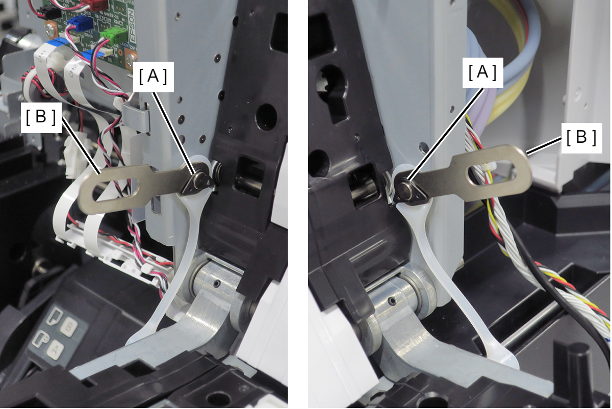
- Remove the Washer (A) and the Strap (B). (Only perform for SC-P8500DM series/SC-T7700DM series/SC-T5700DM series)
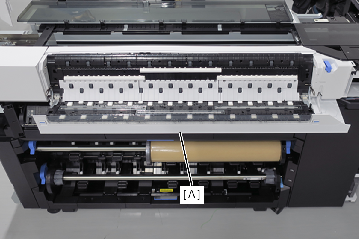
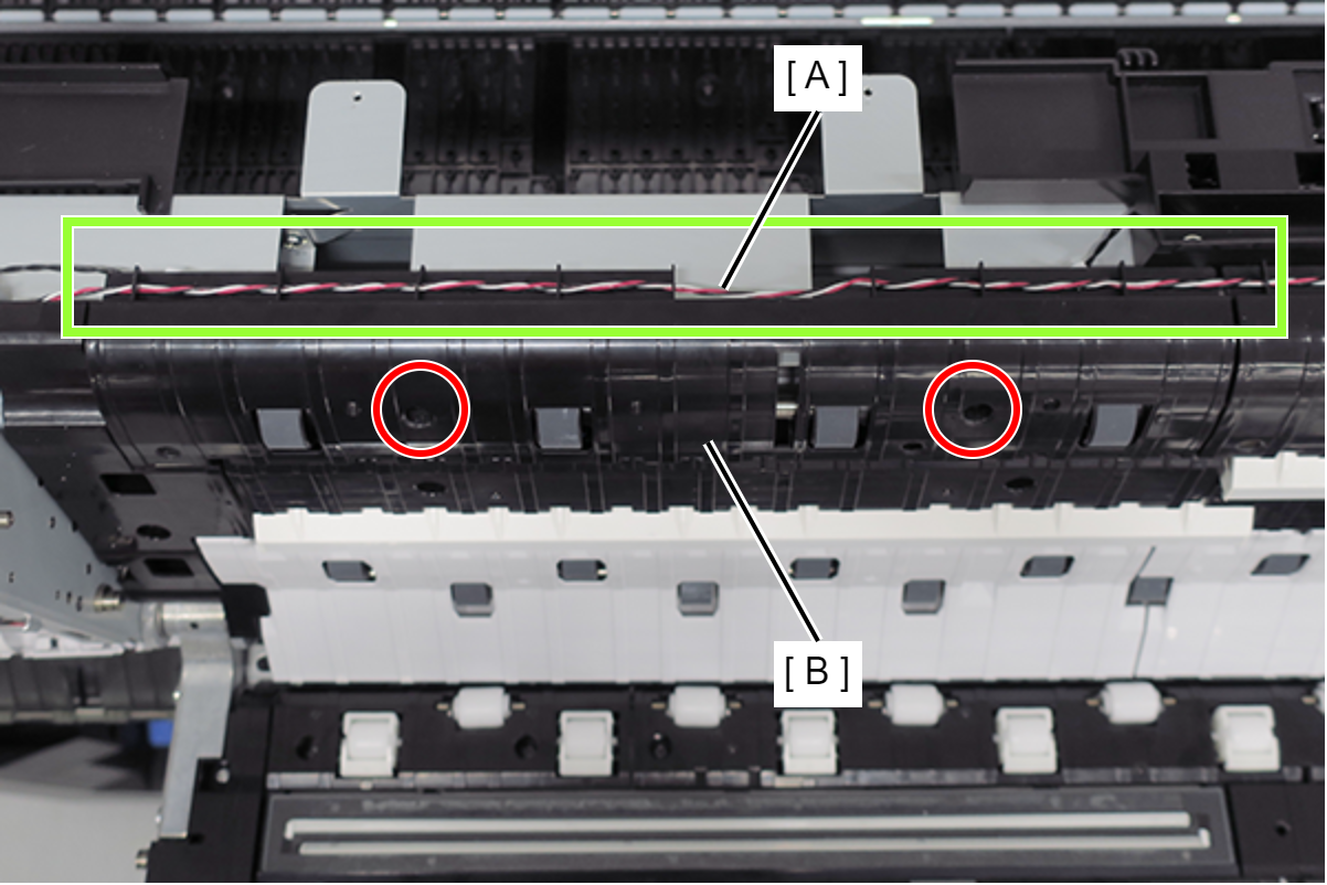
- Release the cable (A) from eight grooves at the rear.
- Remove the two screws, and remove the Left Rear Guide A (B).
- : Silver M3x6 Bind S-tite screw
- Remove the two screws, and remove the Left Rear Guide B (A).
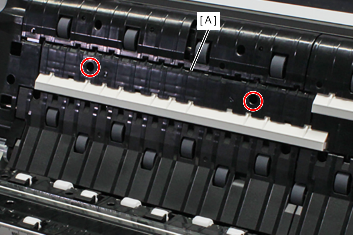
- : Silver M3x6 Bind S-tite screw
- Remove the screw, and remove the Left Edge Rear Guide (A).
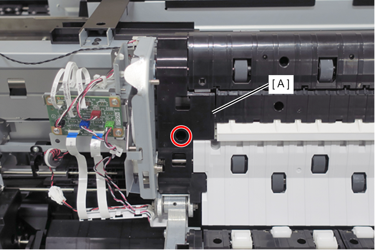
- : Silver M3x6 Bind S-tite screw
 Assembly / 組み立て
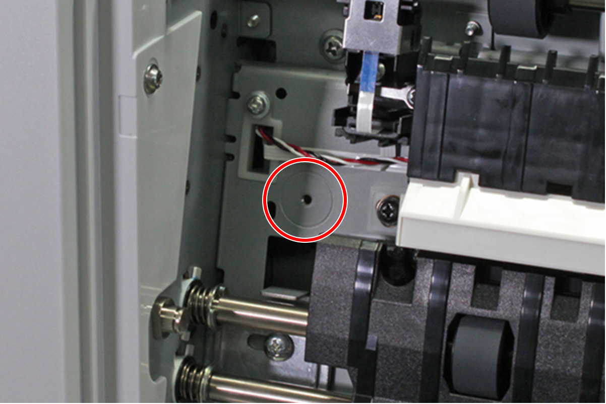
- To prevent the cable from getting caught in the machine when tightening screws, ensure that the cable does not enter the area marked with a circle.
- Remove the two screws, and remove the Center Rear Guide B (A).
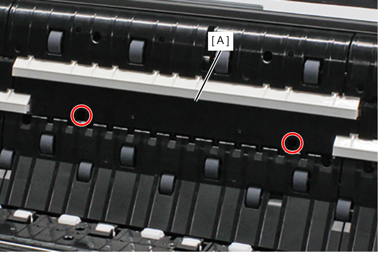
- : Silver M3x6 Bind S-tite screw
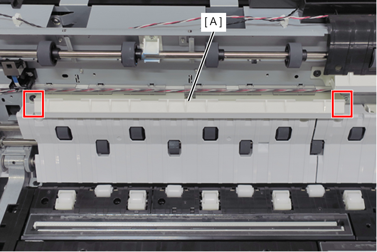
Disengage the two hooks, and remove the White Base Assy Full Side (A).
 Caution / 注意
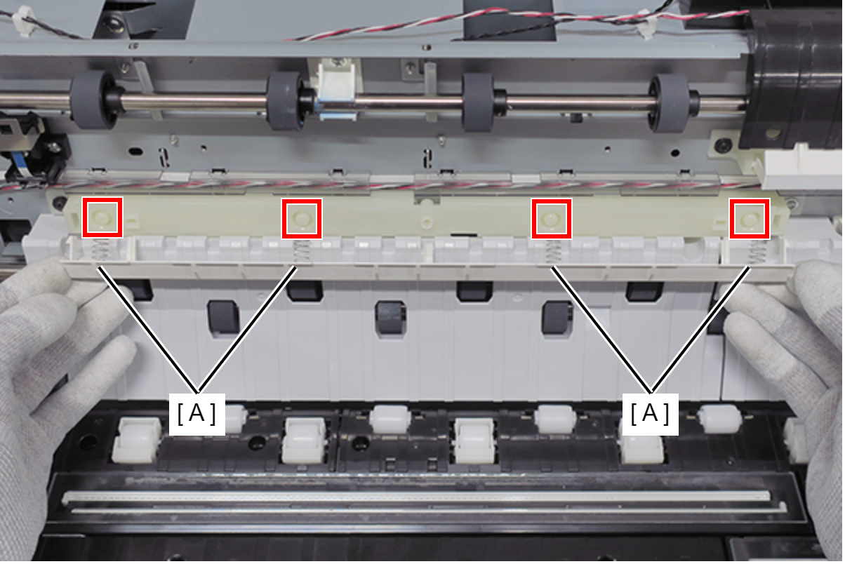
- Take care not to drop the four springs.
Assembly / 組み立て- Attach four springs (A) to the positioning points.
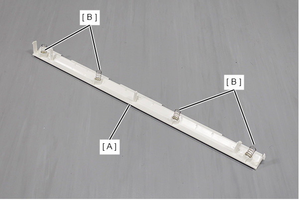
- Remove the four Spring (B) from the White Base Assy Full Side (A).
 Adjustment / 調整 Adjustment / 調整 |
When removing/replacing this part, refer to following page and make sure to perform the specified operations including required adjustment. |