1st Paper Feed Driven Release Sensor/1st Paper Path Paper Detection Sensor
Remove the two screws and remove the Home Side 1st Roll Paper Guide (A).
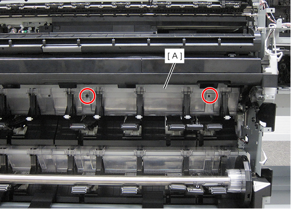
 : Silver M3x8 Cup S-tite screw
 Assemble / 組み立て
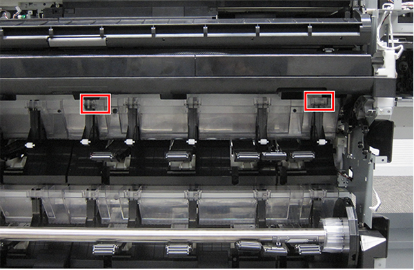
There are two positioning locations.
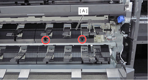
- Remove the two screws and remove the Home Side Upper Roll Paper Guide Parts (A).
- : Black M3x10 Cup P-tite screw
 : Black M3x8 Cup S-tite screw
- Remove the two screws and remove the Roll Paper Guide Upper Right (A).
- : Black M3x10 Cup P-tite screw
- Remove the single screw and remove the Upper Right Roll Paper Guide Parts.
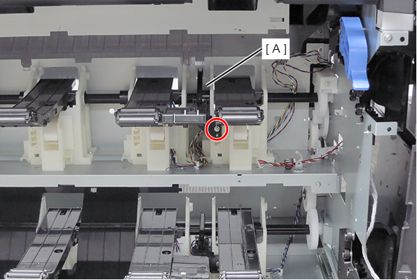
- : Silver M3x10 Cup P-tite screw
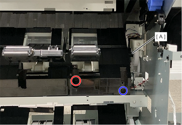
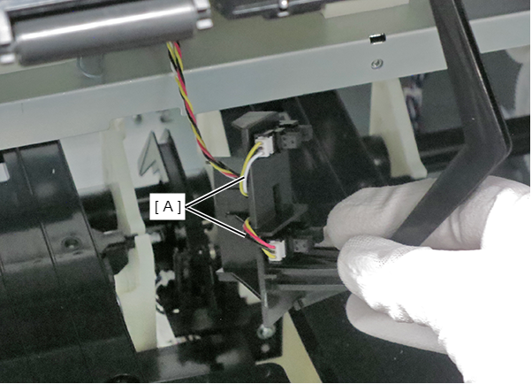
- Disconnect the cables (A) from the two sensor connectors.
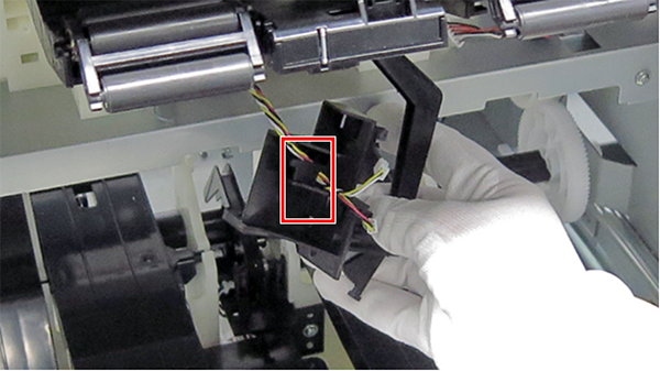
Release the cable from the hook.
 Assemble / 組み立て
- Check the connection destination of the cable.
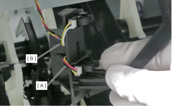
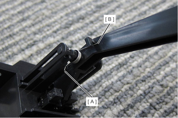
- If the spring comes off, hang the spring foot (short) (A) and spring foot (long) (B) on the hook of the unit, referring to the figure below.
- Check the connection destination of the cable.
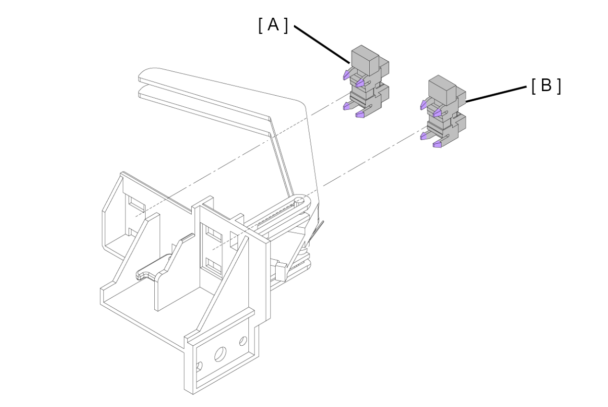
Release the hooks from each of the 4 locations, and remove the 1st Paper Feed Driven Release Sensor (A) and 1st Paper Path Paper Detection Sensor (B).
 Adjustment / 調整 Adjustment / 調整 |
When removing/replacing this part, refer to following page and make sure to perform the specified operations including required adjustment. |