Nip Release Roller/Nip Release Roller Holder
 Check Point / チェックポイント Check Point / チェックポイント |
|
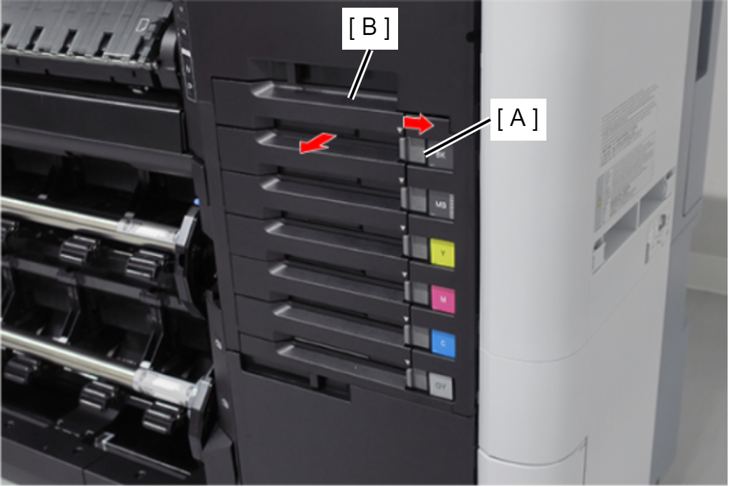
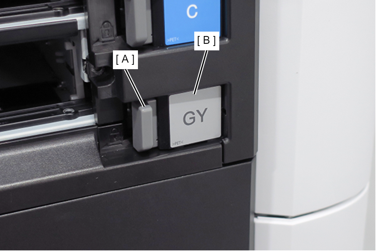
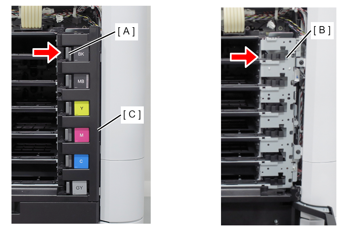
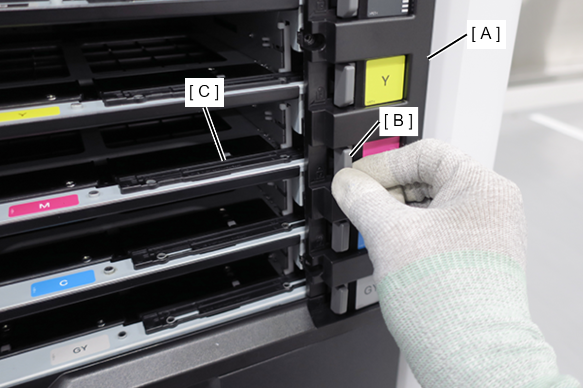
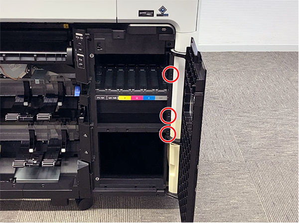
- Release the 6 locks (A), and remove the 6 Ink Pack Trays (B). (Only perform for SC-P8500DL series/SC-T7700DL series)
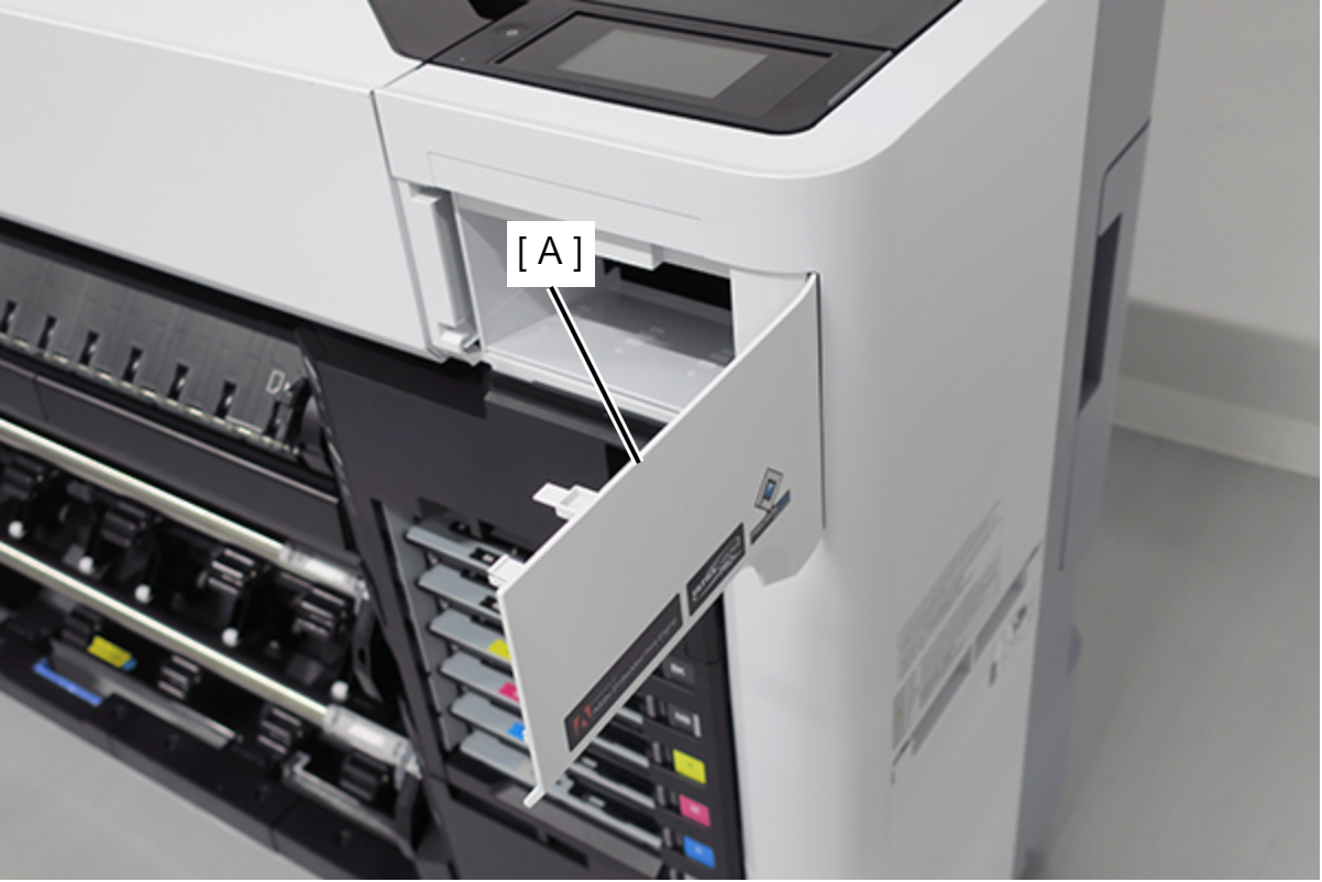
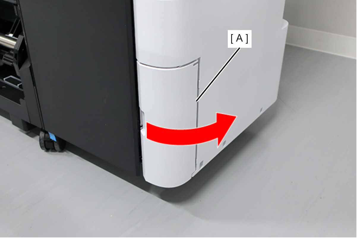
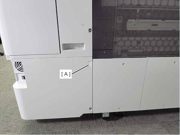
Open the Maintenance Cover (A). (Only perform for SC-P8500DL series/SC-T7700DL series)
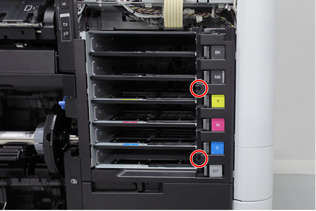
- Remove the screw. (Only perform for SC-P8500DL series/SC-T7700DL series)
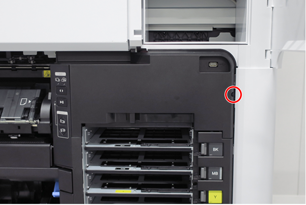
 :Black M3x8 S-tite screw
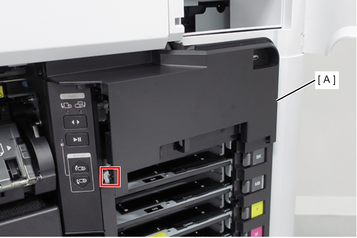
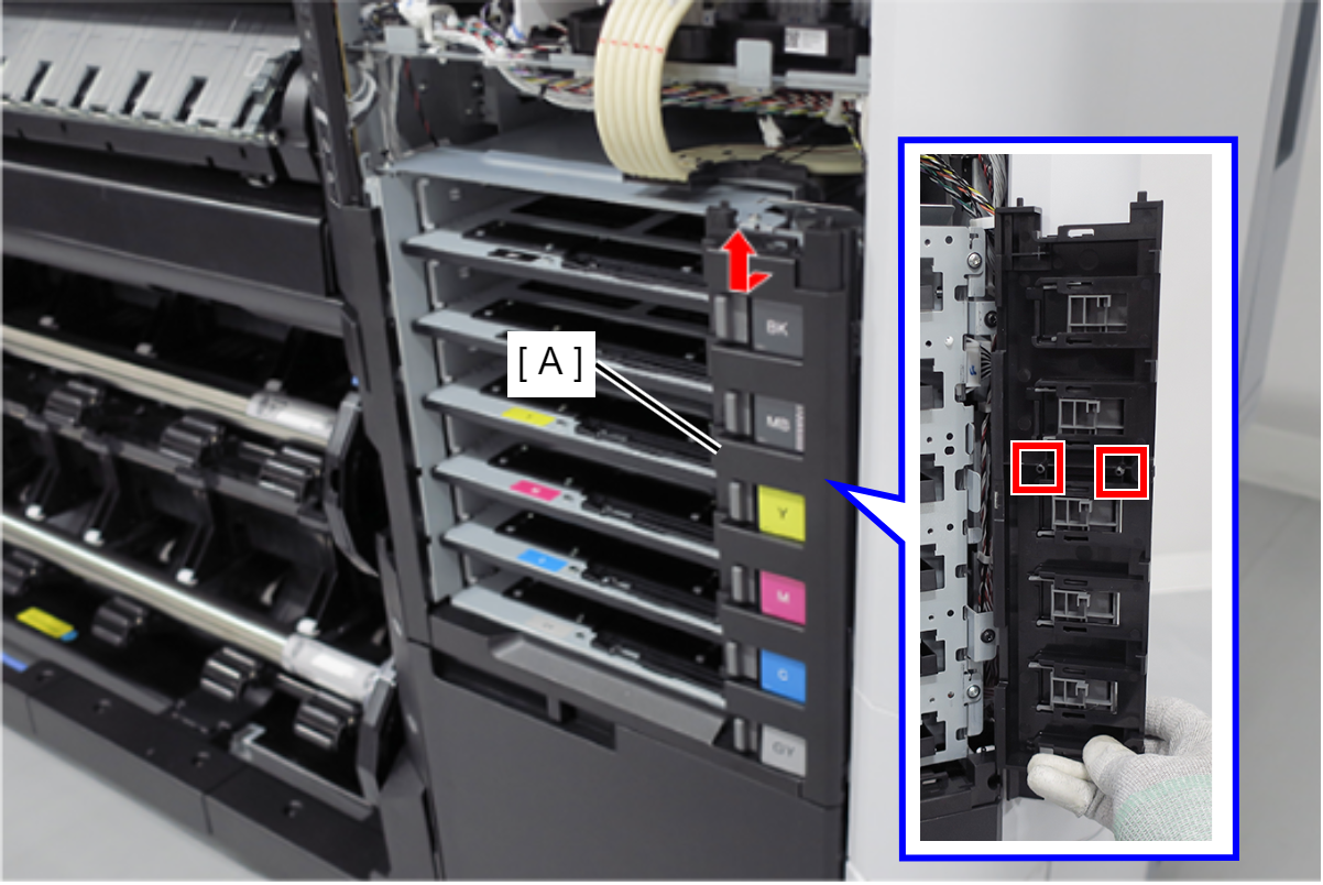
Release the hook, and remove the Ink Holder (RIPS) Upper Cover (A). (Only perform for SC-P8500DL series/SC-T7700DL series)
 Assembly / 組み立て
- Insert the Ink Holder (RIPS) Upper Cover (A) tab (B).
- Insert the Ink Holder (RIPS) Upper Cover (A) hook (C).
Remove the two screws, and remove the USB cable (A). (Only perform for SC-P8500DL series/SC-T7700DL series)
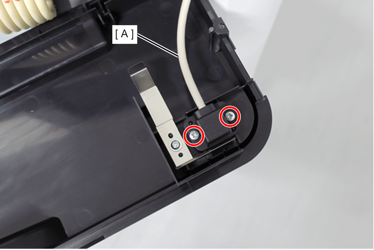
- : Silver M3x8 P-tite screw
Remove the two screws. (Only perform for SC-P8500DL series/SC-T7700DL series)
- : Silver M3x8 S-tite screw
- Pull the Ink Pack Tray Right Side (A) slightly forward and release the 2 dowels. (Only perform for SC-P8500DL series/SC-T7700DL series)
Slide the Ink Pack Tray Right Side (A) upwards to remove. (Only perform for SC-P8500DL series/SC-T7700DL series)
 Assembly / 組み立て
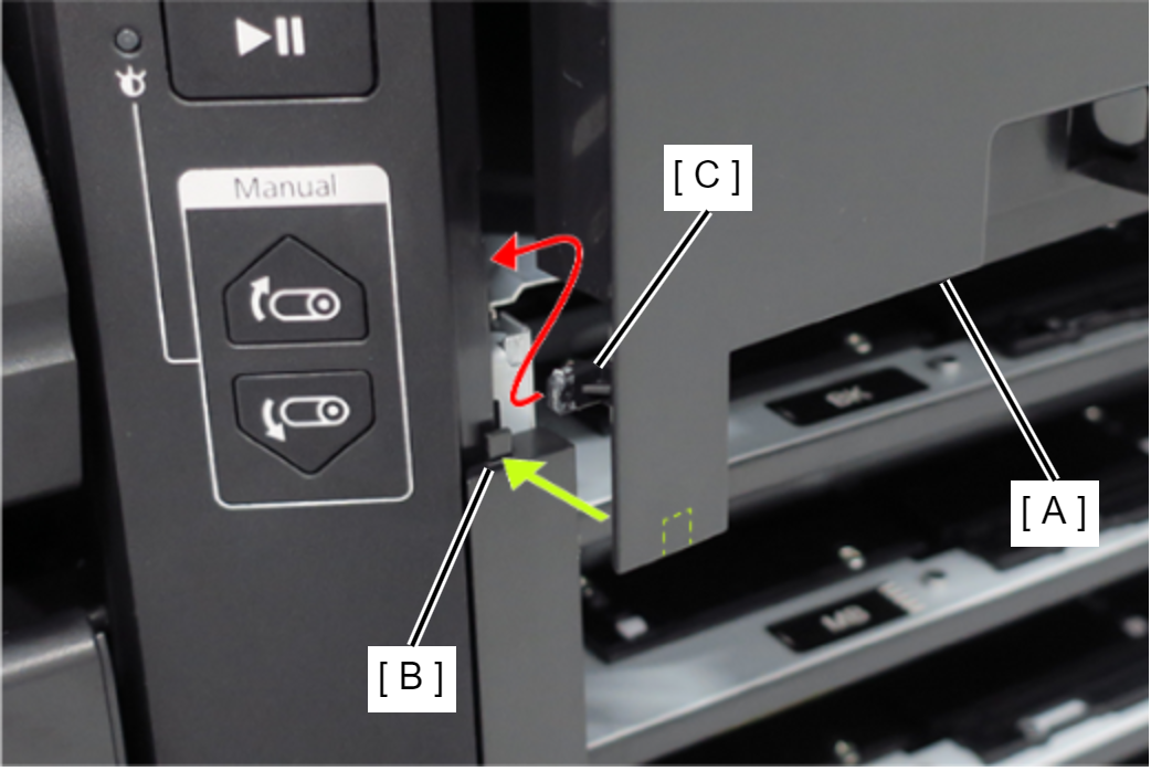
- The gray lock lever (A) and ink plate (B) will come off when removing the Ink Pack Tray Right Side (C). Install them after installing the Ink Pack Tray Right Side (C) in the main unit.
- With the lock lever (A) and tray lever (B) moved to the right side, install the Ink Pack Tray Right Side (C).
- After installing the Ink Pack Tray Right Side (A), move the lock lever (B) and confirm that the tray lever (C) moves in conjunction.
- The gray lock lever (A) and ink plate (B) will come off when removing the Ink Pack Tray Right Side (C). Install them after installing the Ink Pack Tray Right Side (C) in the main unit.
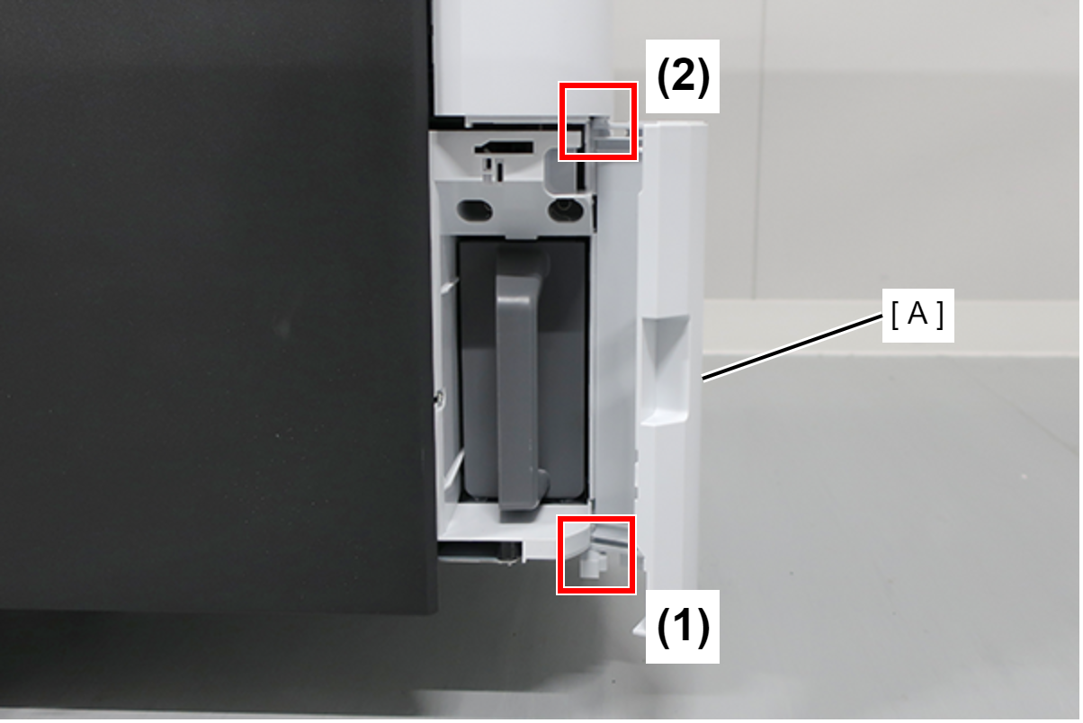
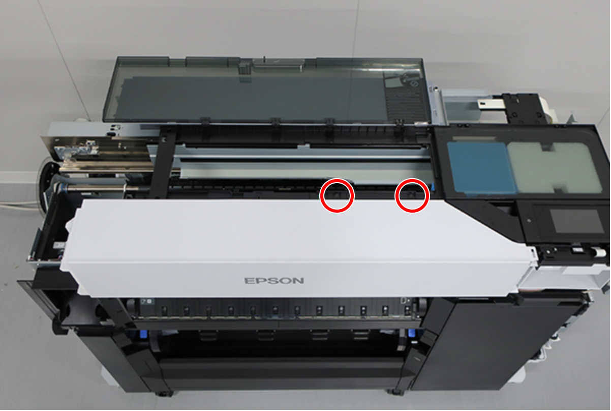
- Open the Maintenance Box Cover (A).
- Release the 2 tabs of the Maintenance Box Cover (A) in the order shown in the figure below, and remove.
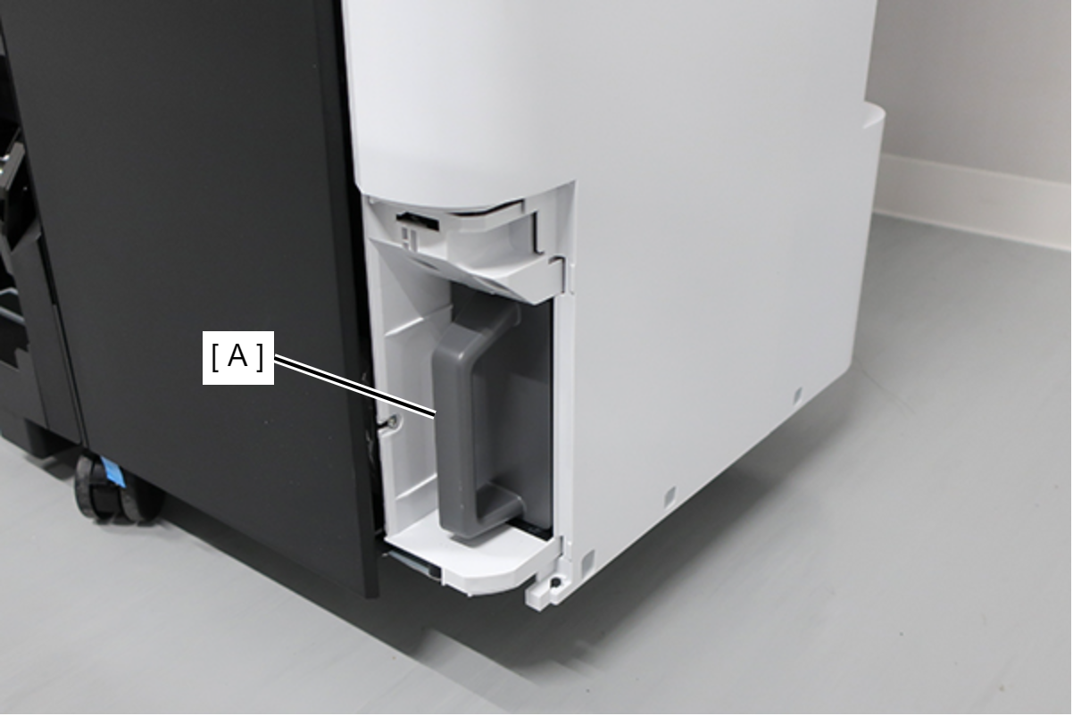
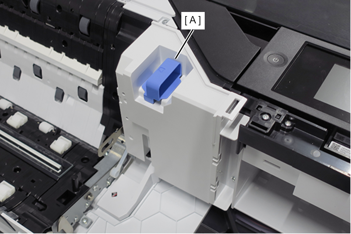
- Remove the Maintenance Box (A).
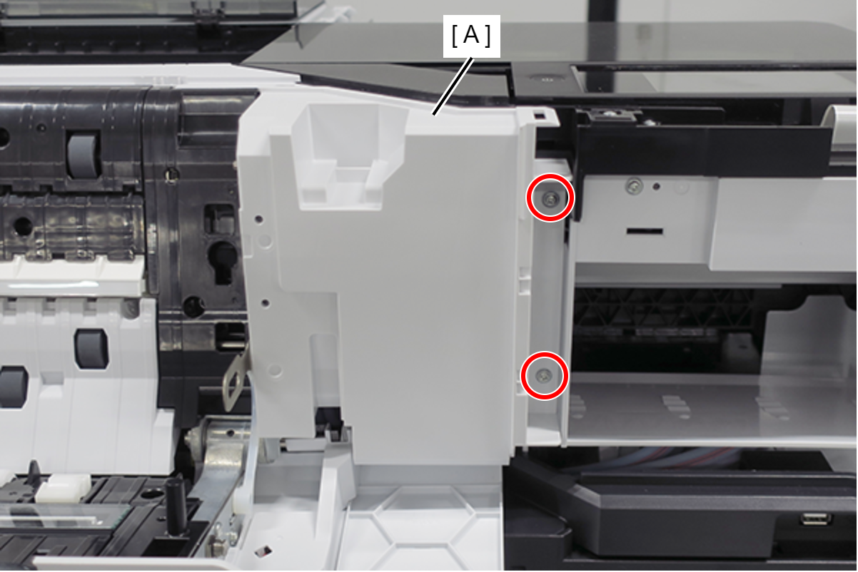
- Remove the screw.
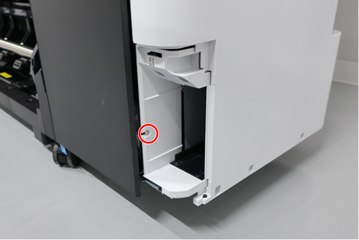
- : : Silver M3x8 Cup S-tite screw
- Insert a flathead screwdriver and release the 2 hooks each, and remove the two screw cover (A).
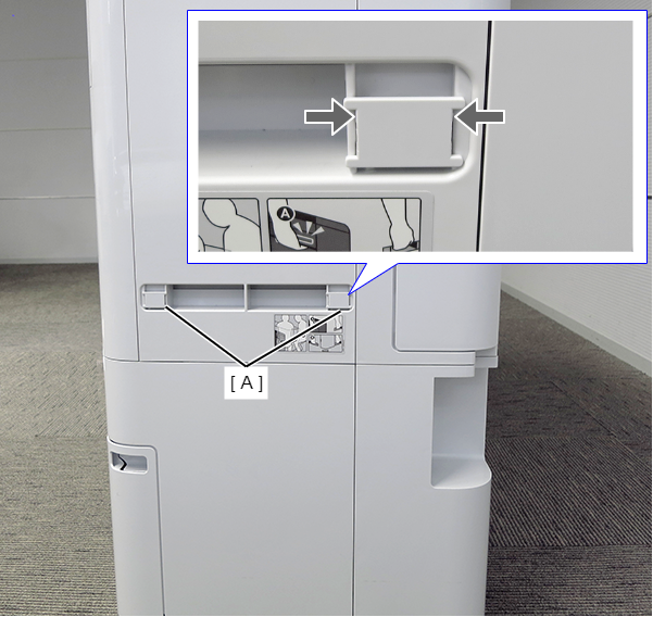
- Insert a flathead screwdriver and release the 2 hooks, and remove the screw cover (A).
- Remove the three screws at the front side.
- : Black M3x8 Cup P-tite screw
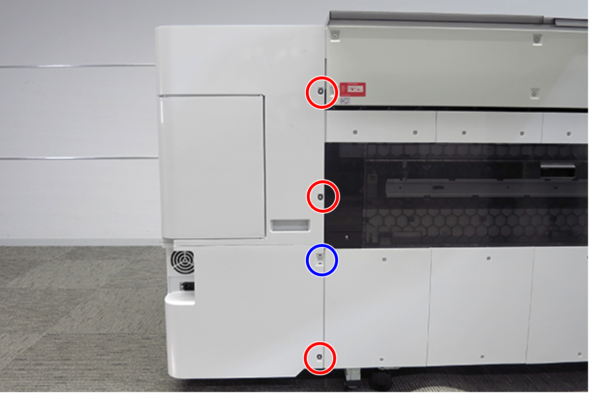
- Remove the five screws at the right side.
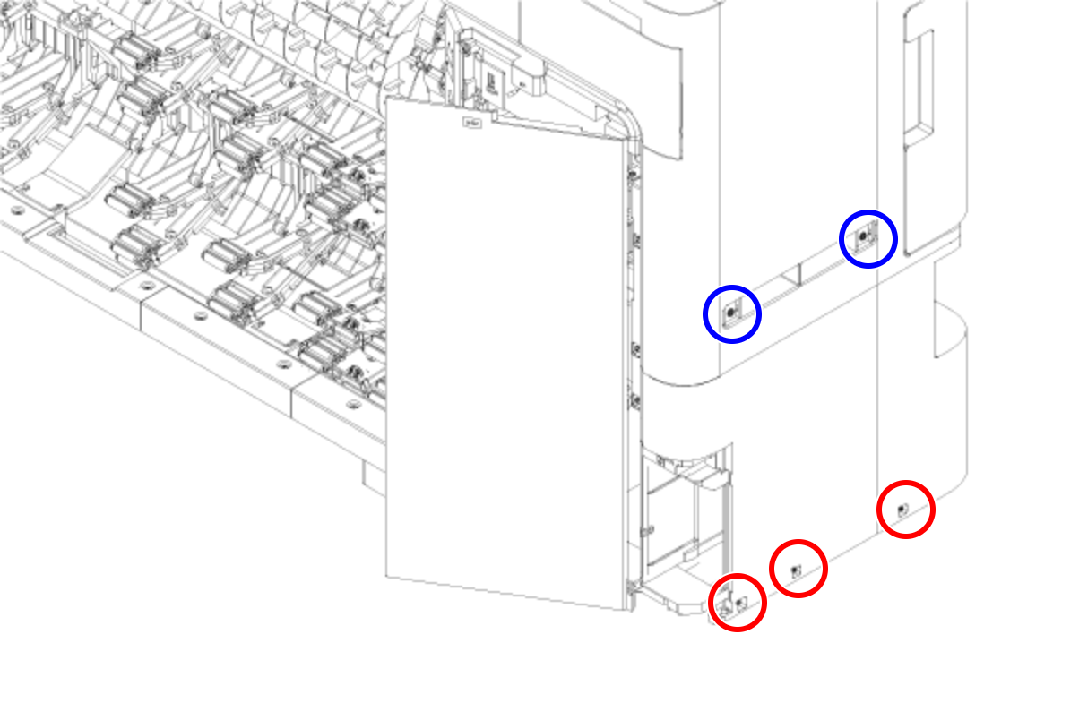
- : Silver M3x8 Cup S-tite screw
 : Silver/M4x8/machine screw
- Remove the four screws at the rear side.
- : Silver M3x8 Cup S-tite screw with plastic washer
- : : Silver M3x8 Cup S-tite screw
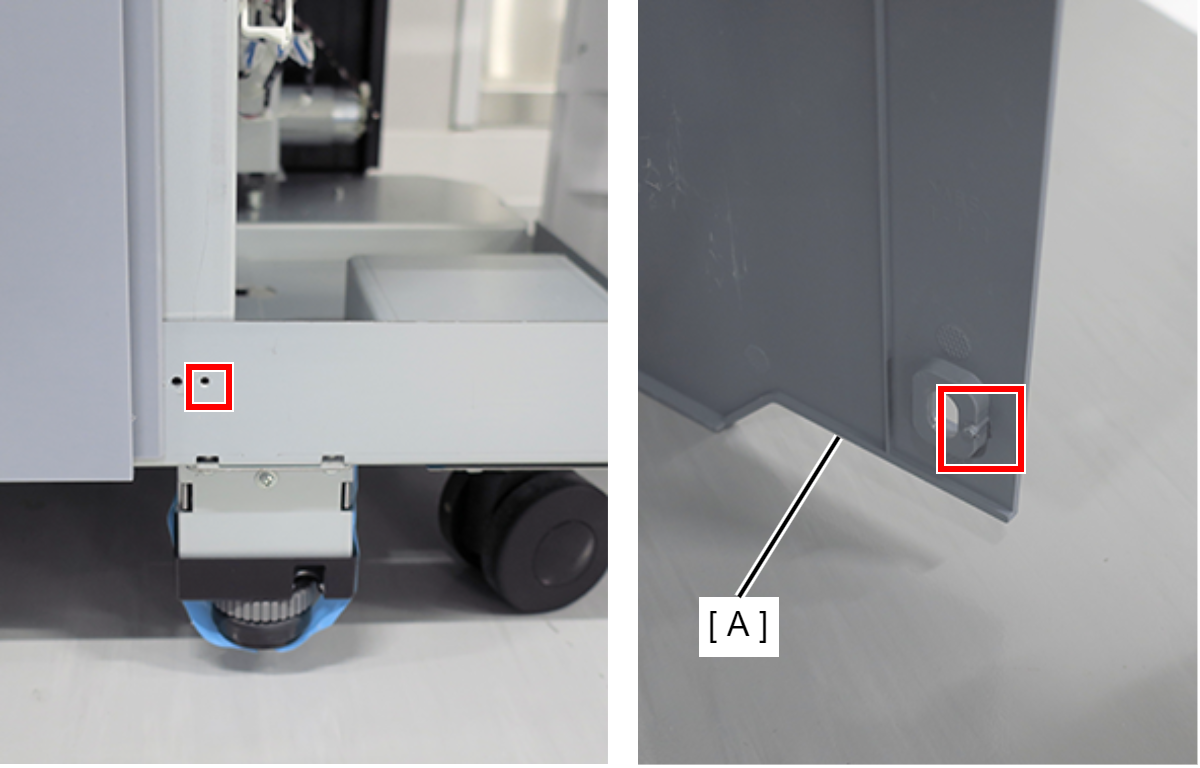
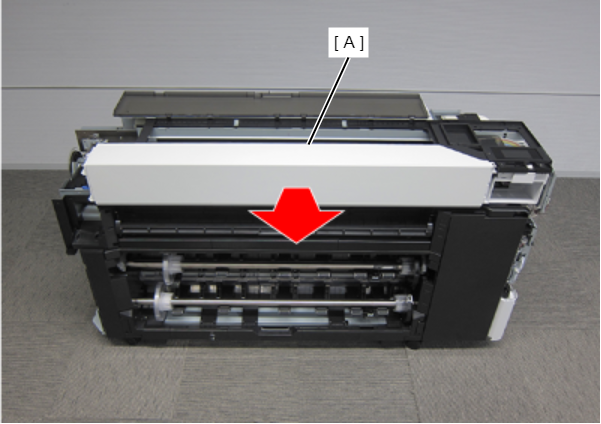
- On the printer rear side, release the dowel of the Home Side Cover Unit (A).
- Insert a flathead screwdriver and release the 2 tabs each, and remove the Home Side Cover Unit (A) in the direction of the arrow.
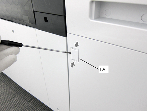
- Insert a flathead screwdriver and release the two hooks, and remove the screw cover (A).
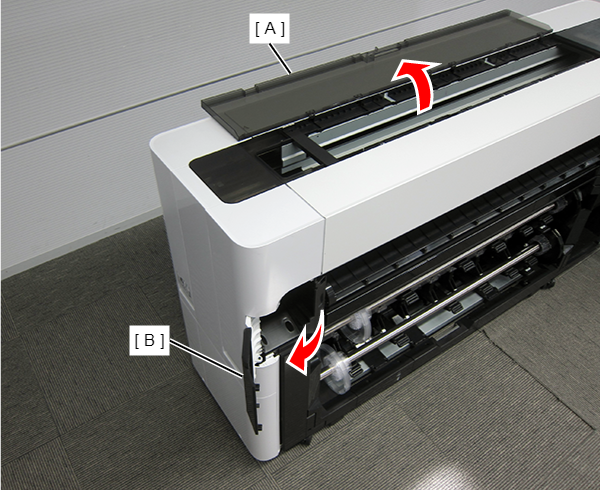
- Open the Printer Cover (A) and the Cutter Cover (B).
- Remove the three screws at the front side.
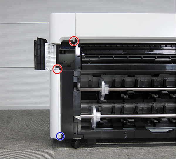
- : Silver M3x10 Cup P-tite screw
- : : Silver M3x8 Cup S-tite screw
- Remove the screw at the top side.
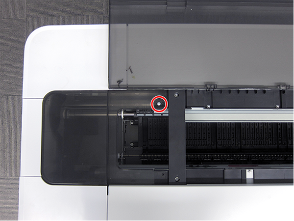
- : : Silver M3x8 Cup S-tite screw
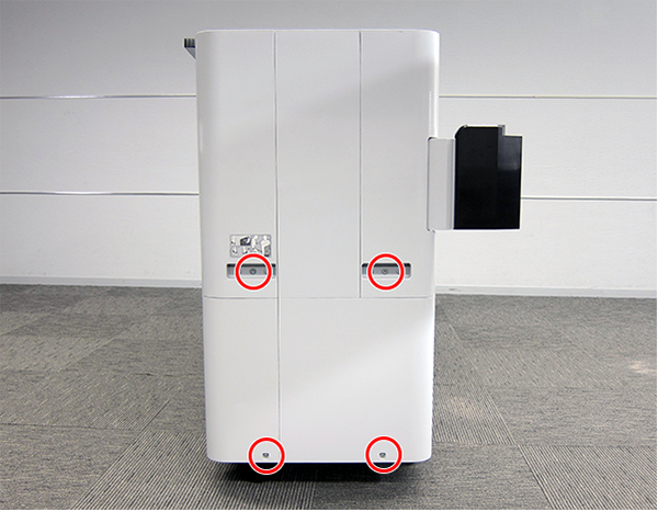
- Remove the four screws at the rear side.
- : Silver M3x8 Cup S-tite screw with plastic washer
- : : Silver M3x8 Cup S-tite screw
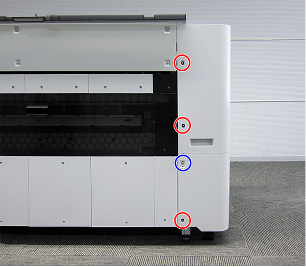
- Remove the four screws at the left side.
- : Silver M3x8 Cup S-tite screw
- : Silver/M4x8/machine screw
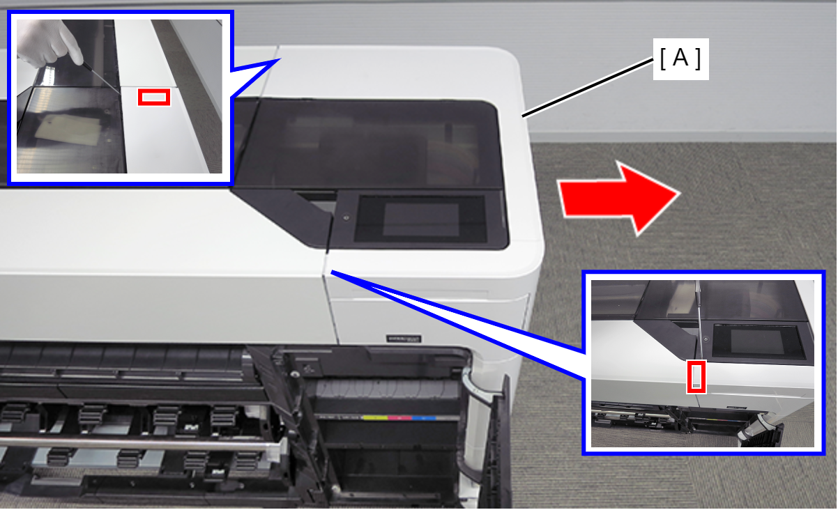
On the printer rear side, release the dowel of the Full Side Cover Unit (A).
Remove the Full Side Cover Unit (A) from the dowels, and remove it while it in the direction of the arrow.
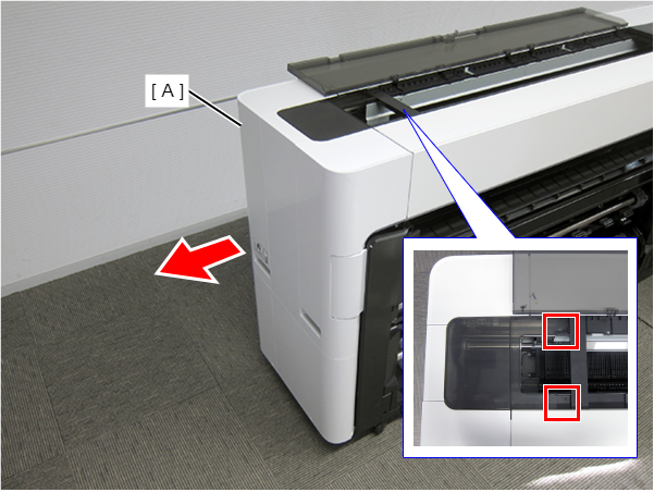 Assemble / 組み立て
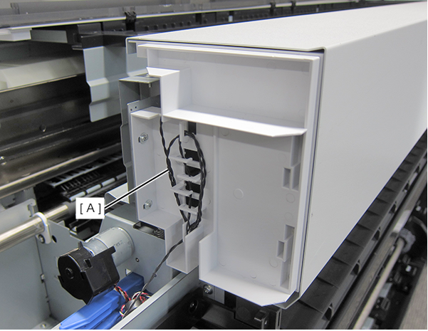
When installing the Full Side Cover Unit (B), carefully the Head FFC (A) so that it does not damage.
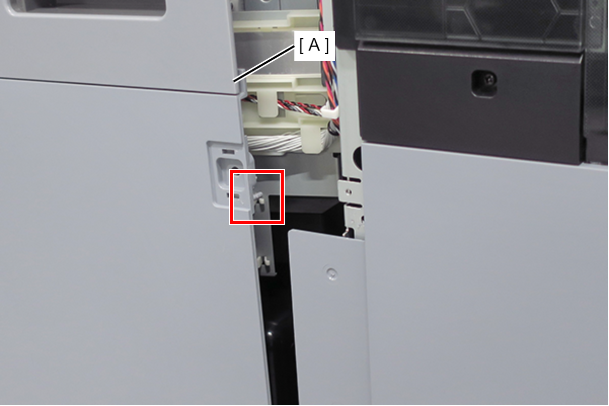
- Release the sensor cable (A). (Only perform for SC-P8500D series/SC-T7700D series/SC-T5700D series/SC-P6500D series/SC-P6500DE series/SC-T3700D series/SC-T3700DE series/SC-P6500E series/SC-T3700E series/SC-P8500DL series/SC-T7700DL series)
- Open the Printer Cover (A). (Only perform for SC-P8500D series/SC-T7700D series/SC-T5700D series/SC-P6500D series/SC-P6500DE series/SC-T3700D series/SC-T3700DE series/SC-P6500E series/SC-T3700E series/SC-P8500DL series/SC-T7700DL series)
Remove the Home Side Top Cover (B). (Only perform for SC-P8500D series/SC-T7700D series/SC-T5700D series/SC-P6500D series/SC-P6500DE series/SC-T3700D series/SC-T3700DE series/SC-P6500E series/SC-T3700E series/SC-P8500DL series/SC-T7700DL series)
Remove the four screws at the front side. (Only perform for SC-P8500D series/SC-T7700D series/SC-T5700D series/SC-P6500D series/SC-P6500DE series/SC-T3700D series/SC-T3700DE series/SC-P6500E series/SC-T3700E series/SC-P8500DL series/SC-T7700DL series)
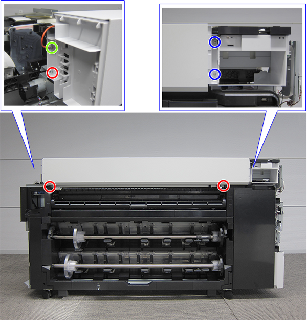
- (Right):Silver M3x8 Cup S-tite screw
- (Left):SC-P8500D series/SC-T7700D series/SC-P8500DL series/SC-T7700DL series: Silver M3x8 Cup S-tite screw, SC-T5700D series/SC-P6500D series/SC-P6500DE series/SC-T3700D series/SC-T3700DE series/SC-P6500E series/SC-T3700E series: Silver M4x6 Shoulder Screw
 : Silver M3x10 Cup P-tite screw
Assemble / 組み立てTighten the right green screw with the grounding cable. (SC-P8500D series/SC-T7700D series/SC-P8500DL series/SC-T7700DL series only)
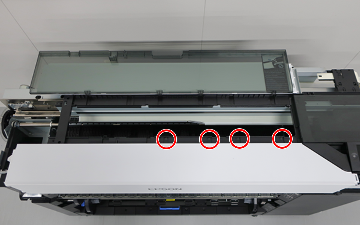
- Remove the screws on the top. (Only perform for SC-P8500D series/SC-T7700D series/SC-T5700D series/SC-P6500D series/SC-P6500DE series/SC-T3700D series/SC-T3700DE series/SC-P6500E series/SC-T3700E series/SC-P8500DL series/SC-T7700DL series)
SC-P8500D series/SC-T7700D series/SC-P8500DL series/SC-T7700DL series: 6 pcs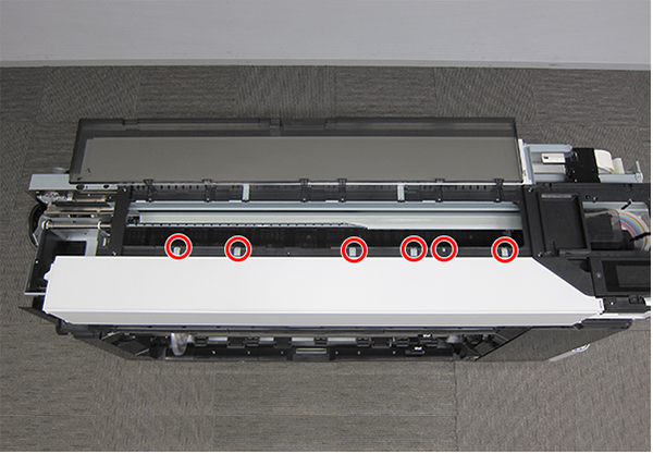
- : Black M3x8 Cup S-tite screw
- : Black M3x8 Cup S-tite screw
- : Black M3x8 Cup S-tite screw
- Remove the Front Top Cover (A) frontward. (Only perform for SC-P8500D series/SC-T7700D series/SC-T5700D series/SC-P6500D series/SC-P6500DE series/SC-T3700D series/SC-T3700DE series/SC-P6500E series/SC-T3700E series/SC-P8500DL series/SC-T7700DL series)
- Remove the Button (A). (Only perform for SC-P8500DM series/SC-T7700DM series/SC-T5700DM series)
- Remove the two screws, and then remove the Scanner Home Side Cover (A). (Only perform for SC-P8500DM series/SC-T7700DM series/SC-T5700DM series)
- : Silver M3x8 Cup P-tite screw
- Push two buttons (A), and open the Scanner Unit (B). (Only perform for SC-P8500DM series/SC-T7700DM series/SC-T5700DM series)
- Remove the screw on the printer home side. (Only perform for SC-P8500DM series/SC-T7700DM series/SC-T5700DM series)
- Remove the C Shape Washer (A). (Only perform for SC-P8500DM series/SC-T7700DM series/SC-T5700DM series)
- : Black M3x4 Cup Step type S-tite screw
- Remove the Fixing Slider (A) from shaft. (Only perform for SC-P8500DM series/SC-T7700DM series/SC-T5700DM series)
- Remove the screw on the printer full side. (Only perform for SC-P8500DM series/SC-T7700DM series/SC-T5700DM series)
- Remove the C Shape Washer (A). (Only perform for SC-P8500DM series/SC-T7700DM series/SC-T5700DM series)
- : Black M3x4 Cup Step type S-tite screw
- Remove the Fixing Slider (A) from shaft. (Only perform for SC-P8500DM series/SC-T7700DM series/SC-T5700DM series)
- Open the Scanner Unit (A). (Only perform for SC-P8500DM series/SC-T7700DM series/SC-T5700DM series)
- Release the sensor cable (A). (Only perform for SC-P8500DL series/SC-T7700DL series)
- Remove the two screws. (Only perform for SC-P8500DL series/SC-T7700DL series)
- : Silver M3x8 Cup S-tite screw
- Remove the screw, and then remove the Scanner Full Side Front Cover (A). (Only perform for SC-P8500DM series/SC-T7700DM series/SC-T5700DM series)
- : Silver M3x8 Cup S-tite screw
Check Point / チェックポイント- Scanner Full Side Front Cover of SC-T5700DM series
- Remove the C Shape Washer (A) and the Fixing Slider (B). (Only perform for SC-P8500DM series/SC-T7700DM series/SC-T5700DM series)
- Remove the Washer (A) and the Strap (B). (Only perform for SC-P8500DM series/SC-T7700DM series/SC-T5700DM series)
- Remove the four screws. (Only perform for SC-P8500DM series/SC-T7700DM series/SC-T5700DM series)
- :Silver M3x8 P-tite screw with built-in washer
- Hang each of the two fixing sliders (A) on the shaft. (Only perform for SC-P8500DM series/SC-T7700DM series/SC-T5700DM series)
Release the 10 hooks and remove the Scanner Front Cover (A). (Only perform for SC-P8500DM series/SC-T7700DM series/SC-T5700DM series)
 Assembly / 組み立て
- Install the Scanner Front Cover (A) while engaging its 10 hooks (B) and 13 tabs (C) with the positioning points on the scanner.
- Install the Scanner Front Cover (A) while engaging its 10 hooks (B) and 13 tabs (C) with the positioning points on the scanner.
- Remove the three screws, and then remove the Scanner Front Top Cover (A). (Only perform for SC-P8500DM series/SC-T7700DM series/SC-T5700DM series)
- : Silver M3x6 Cup S-tite screw
Assembly / 組み立て- Install the Scanner Front Top Cover (A) while inserting its three dowels into the positioning holes in the scanner.
- Remove the eight screws and then remove the Printer Top Cover (A). (Only perform for SC-P8500DM series/SC-T7700DM series/SC-T5700DM series)
 : Silver M3x8 Cup P-tite screw
- : Silver M3x8 Cup S-tite screw
 : Black M3x8 Cup S-tite screw
- Open the Rear Cover (A).
- Remove the two screws.
- Release the two hooks of the Housing Rear Upper 1 (B) while sliding it upward, and remove it.
- : Silver M3x8 Cup S-tite screw
- Remove the two screws.
- Release the two hooks of the Housing Rear Upper 2 (A) while sliding it upward, and remove it.
- : Silver M3x8 Cup S-tite screw
- Remove the two screws.
- Release the two hooks of the Housing Rear Upper 3 (A) while sliding it upward, and remove it.
- : Silver M3x8 Cup S-tite screw
- Remove the two screws.
- Release the two hooks of the Housing Rear Upper 4 (A) while sliding it upward, and remove it.
- : Silver M3x8 Cup S-tite screw
- Remove the two screws.
- : Silver M3x8 Cup S-tite screw
- Open the Rear Cover (A).
- Release the hook while sliding the Housing Rear Full Middle Cover (A) upward, and remove it.
- Check the Board Paper Guide Roller (A) to remove. (Only perform for SC-P8500D series/SC-T7700D series/SC-T5700D series/SC-P8500DL series/SC-T7700DL series/SC-P8500DM series/SC-T7700DM series/SC-T5700DM series)
- Remove the screw. (Only perform for SC-P8500D series/SC-T7700D series/SC-T5700D series/SC-P8500DL series/SC-T7700DL series/SC-P8500DM series/SC-T7700DM series/SC-T5700DM series)
- Slide the Board Paper Guide Roller (A) in the direction of the arrow to remove. (Only perform for SC-P8500D series/SC-T7700D series/SC-T5700D series/SC-P8500DL series/SC-T7700DL series/SC-P8500DM series/SC-T7700DM series/SC-T5700DM series)
- : Silver M3x10 Cup P-tite screw
Assembly / 組み立てInstall while holding the Board Paper Guide Roller (A).
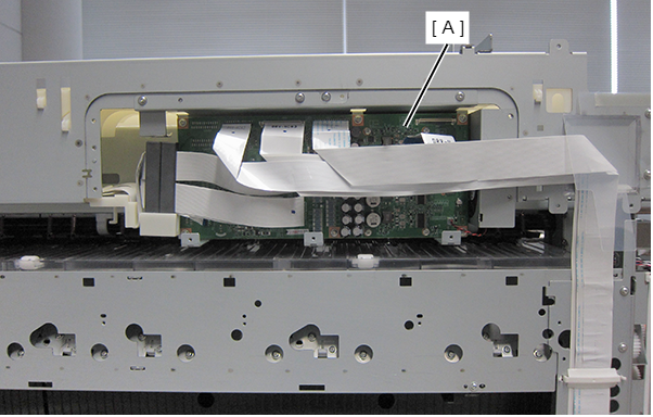
- Remove the 2 FFC Clamps (A).
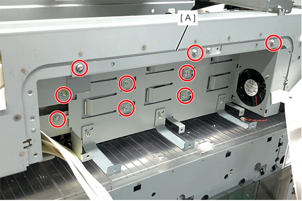
- Remove the 7 screws and then remove the plate (B).
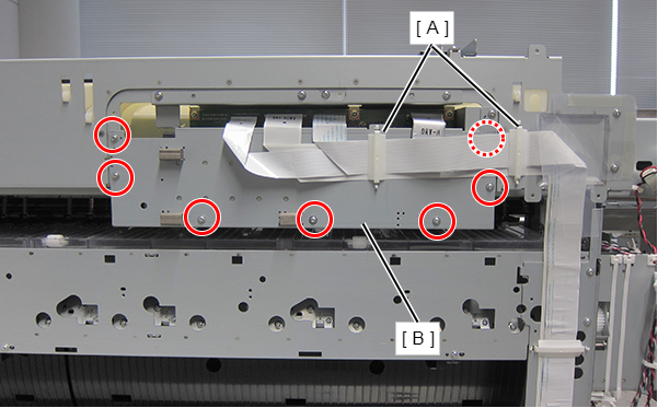
- : Silver M3x8 Cup S-tite screw
- Release the connector lock, and remove the FFC from the CH83 DRV-H Board connectors (CN1 and CN3).
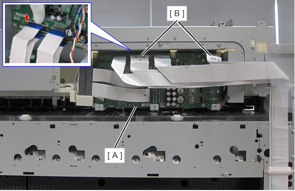
- Remove the remaining FFC and the cables connected to the CH83 DRV-H Board.
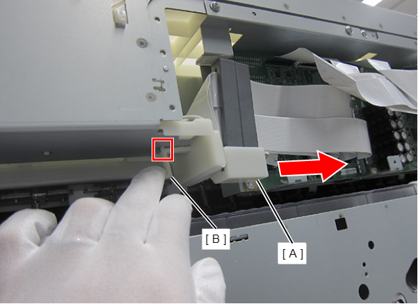
- Push down the lever of the FFC holder to disengage the dowel, and slide the FFC Holder to detach it.
- Remove the six screws.
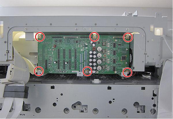
- : Silver M3x8 Cup S-tite screw
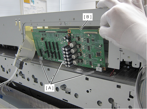
- Remove the CH83 DRV-H Board (B) avoiding contact with the three screw receivers (A).
- Remove the nine screws, and then remove the Drive H Board Frame (A).
- : Silver M3x8 Cup S-tite screw
- Remove screws, and remove the Head FFC Cover (A) upwards.
SC-P8500D series/SC-T7700D series/SC-T5700D series/SC-P8500DL series/SC-T7700DL series/SC-P8500DM series/SC-T7700DM series/SC-T5700DM series: 2 pcs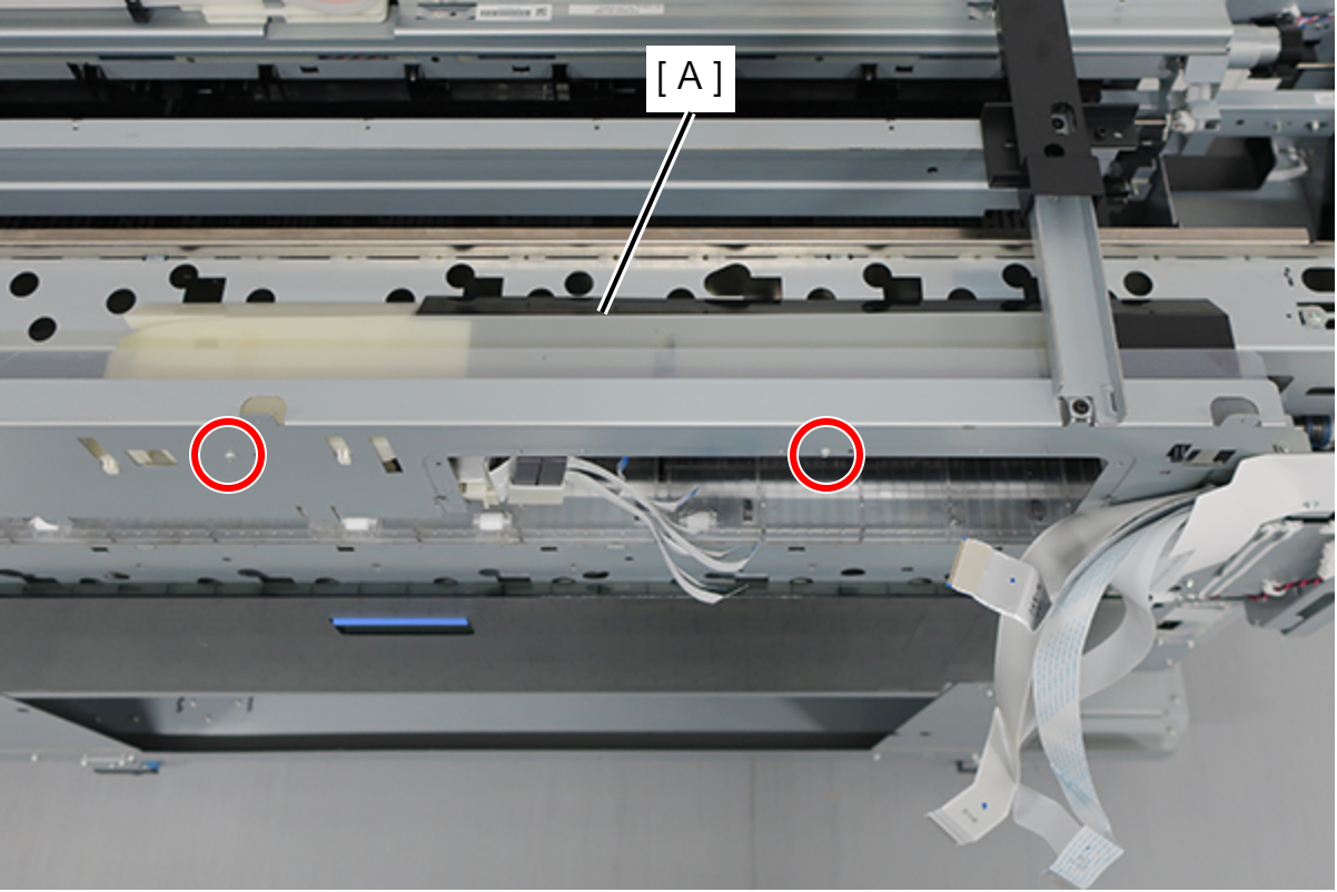
- : Silver M3x10 Cup P-tite screw
- : Silver M3x10 Cup S-tite screw
- Check the Board Paper Guide Roller (A) to remove.
SC-P8500D series/SC-T7700D series/SC-T5700D series/SC-P8500DL series/SC-T7700DL series/SC-P8500DM series/SC-T7700DM series/SC-T5700DM series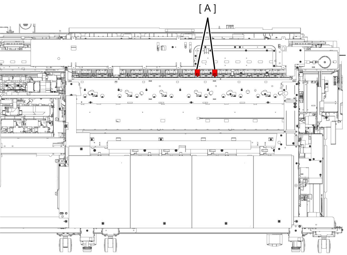
SC-P6500D series/SC-P6500DE series/SC-P6500DE series/SC-T3700DE series/SC-P6500E series/SC-T3700E series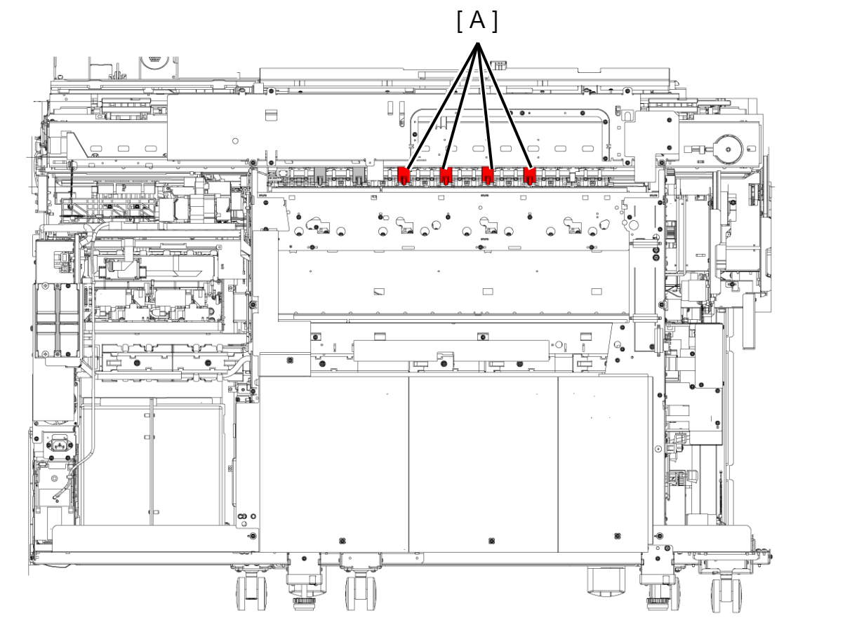
- Remove the screw.
- Slide the Board Paper Guide Roller (A) in the direction of the arrow to remove.
- : Silver M3x10 Cup P-tite screw
Assembly / 組み立てInstall while holding the Board Paper Guide Roller (A).
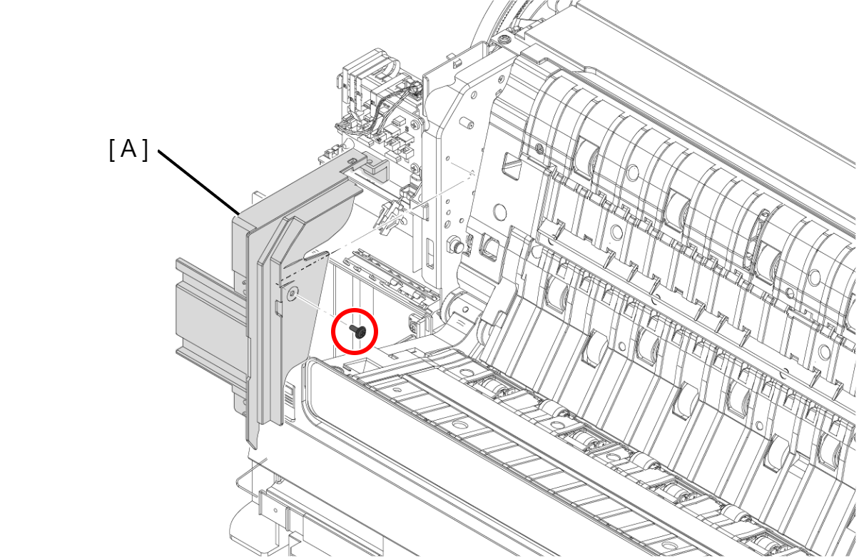
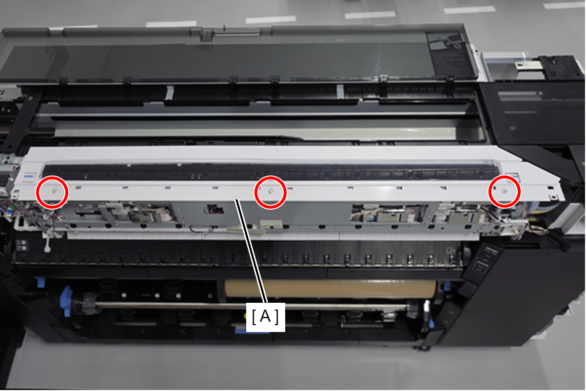
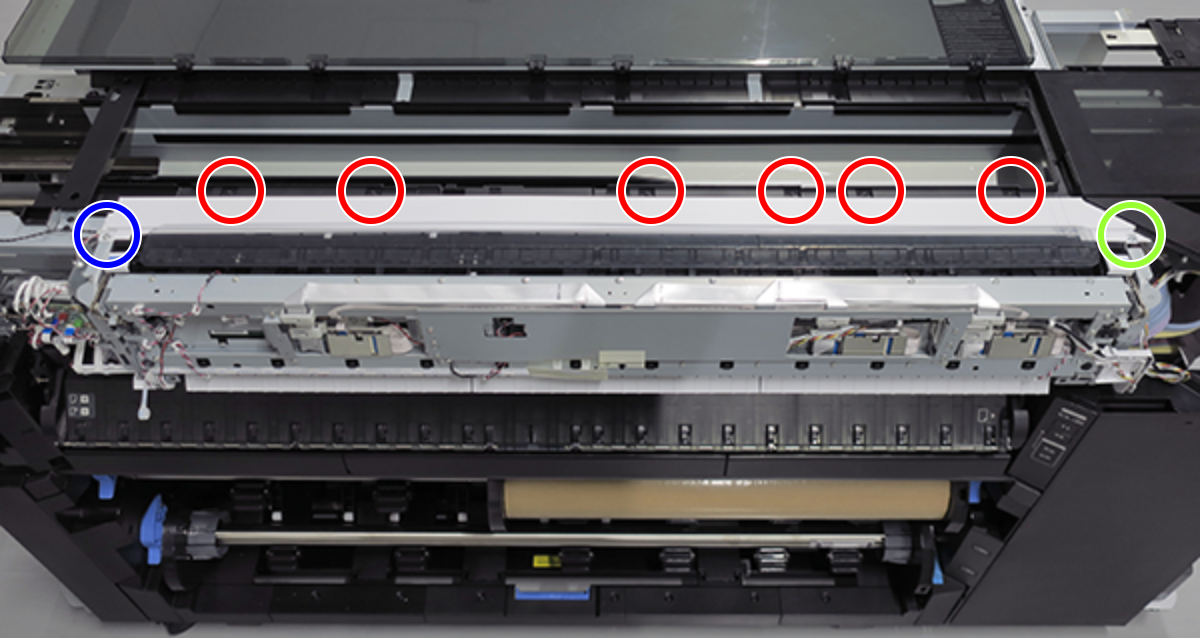
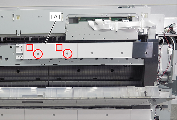
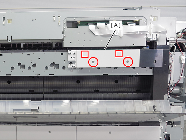
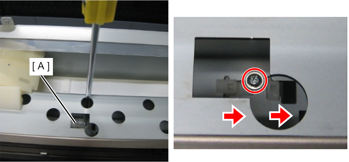
- Remove the screw.
- Peel off the Double-sided Tape on the two FFC.
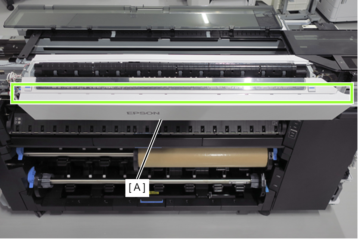
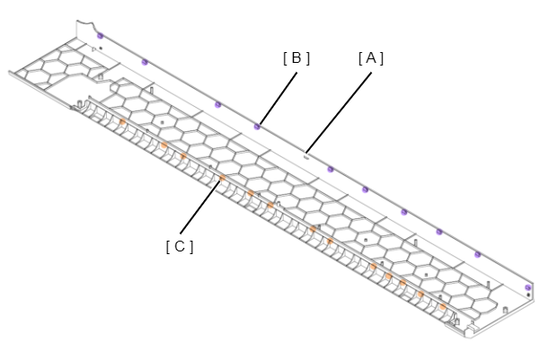
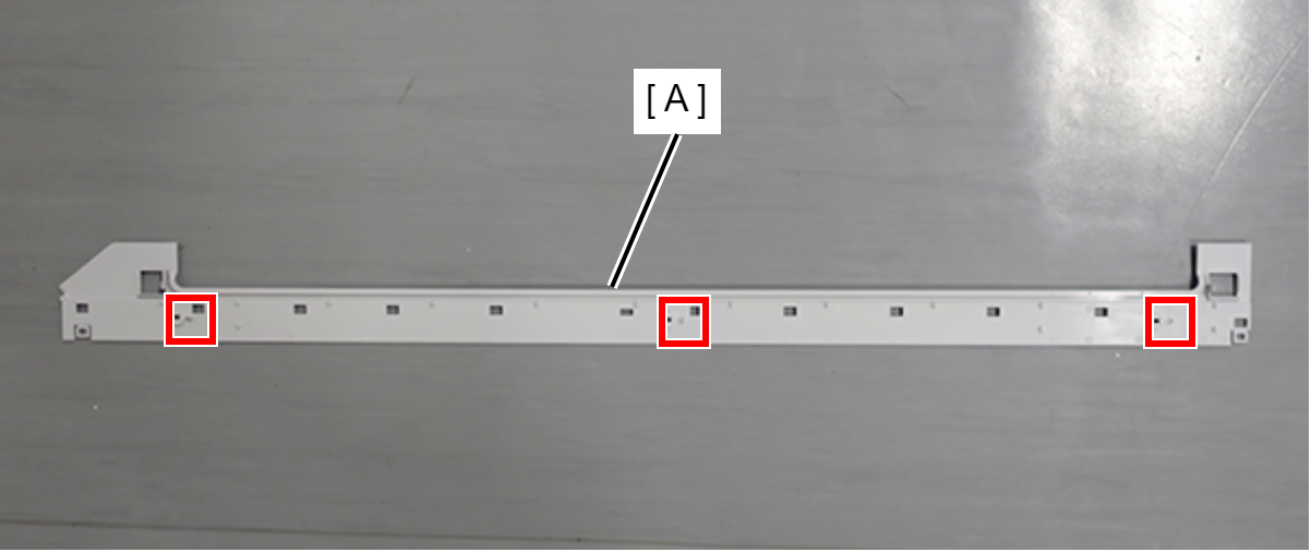
- Release the Paper Guide Rear Home (A) from the two hooks while sliding it in the direction of the arrow.
- Pull out the Paper Guide Rear Home (A) backward wile lifting.
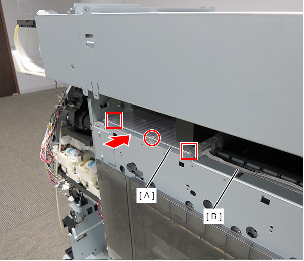
- : Silver M3x8 Cup S-tite screw
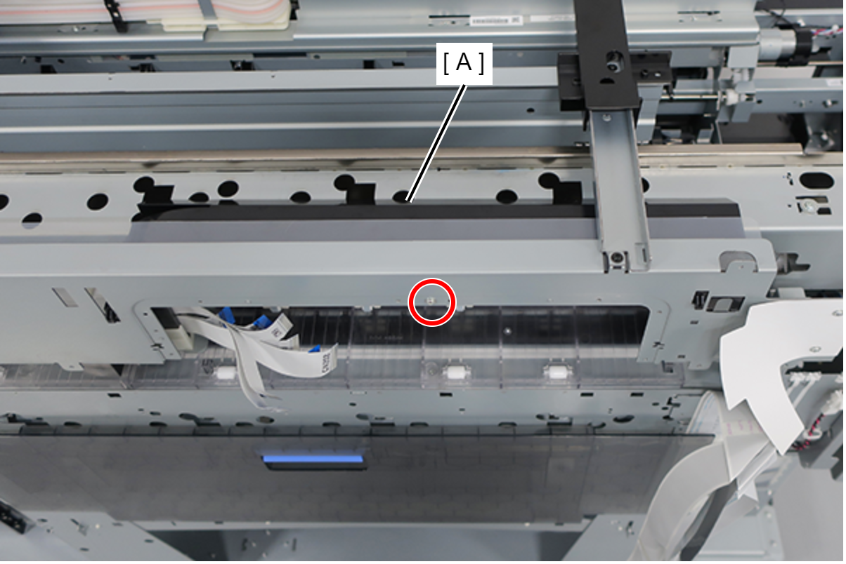
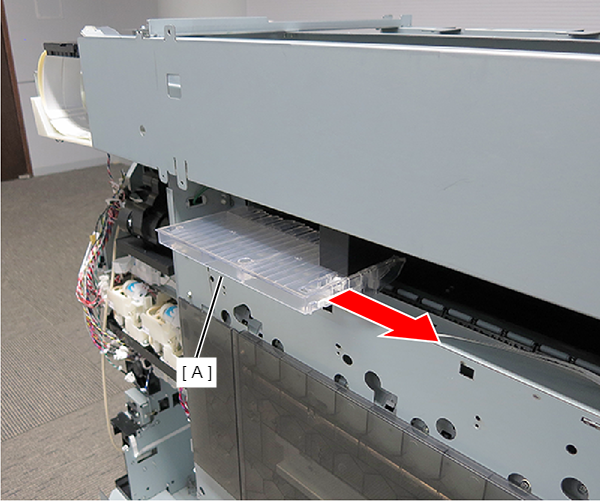
- Remove the Paper Guide Rear Home (A) while sliding the Full side.
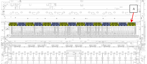
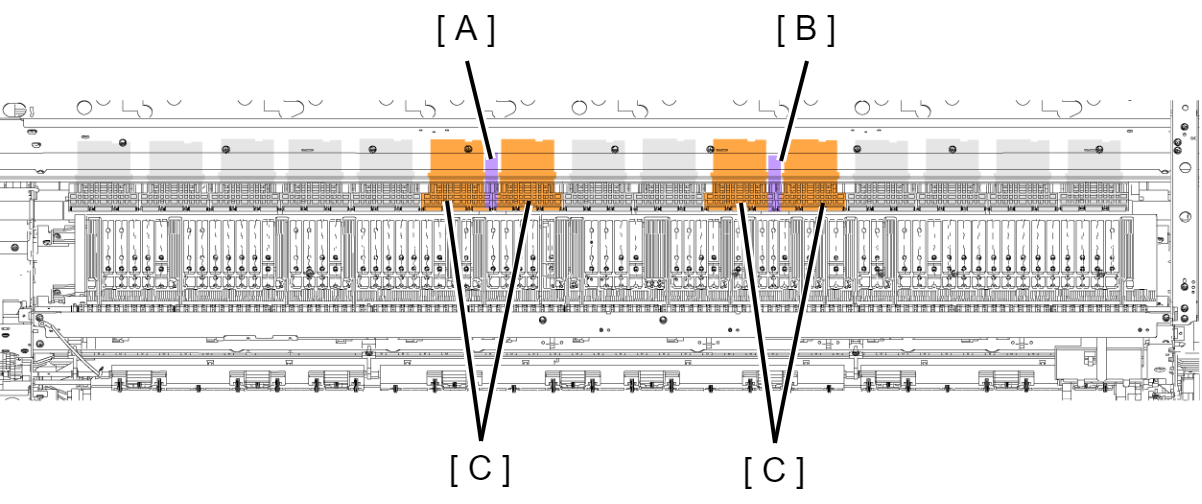
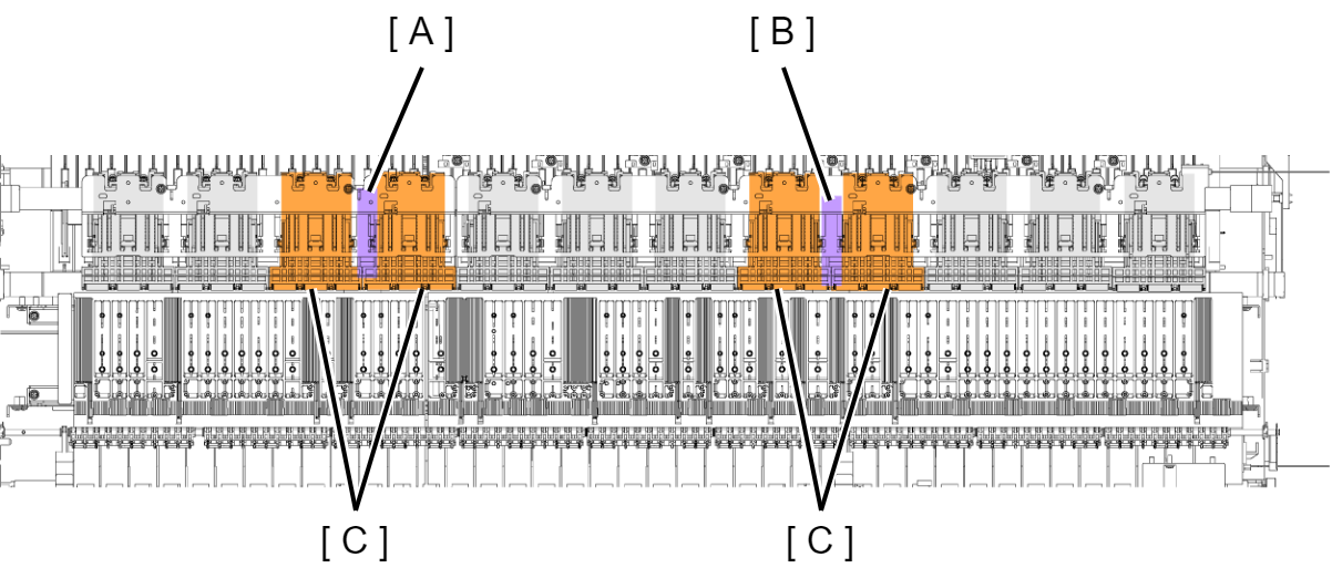
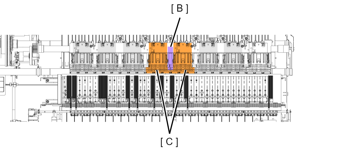
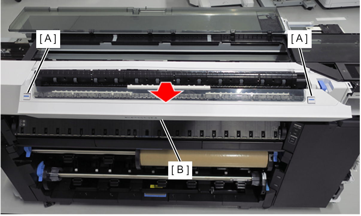
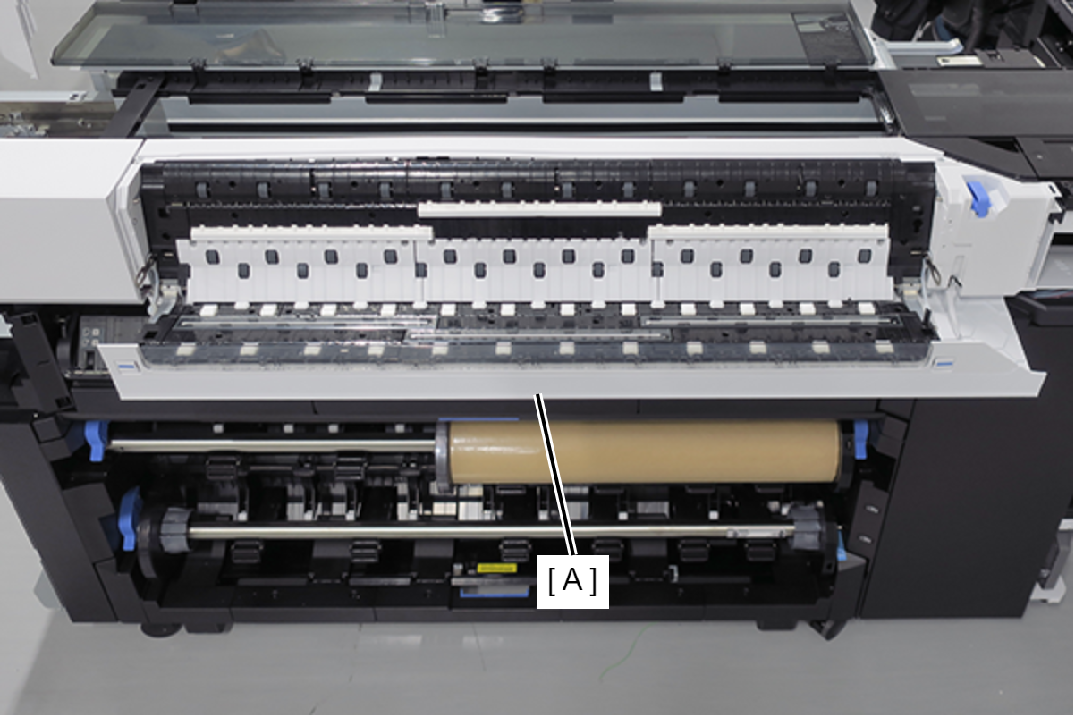
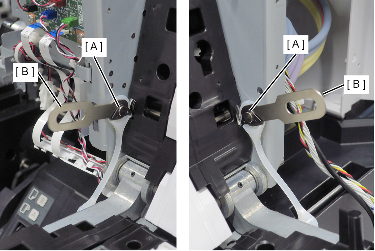
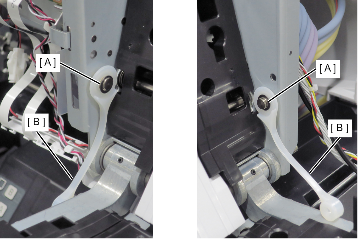
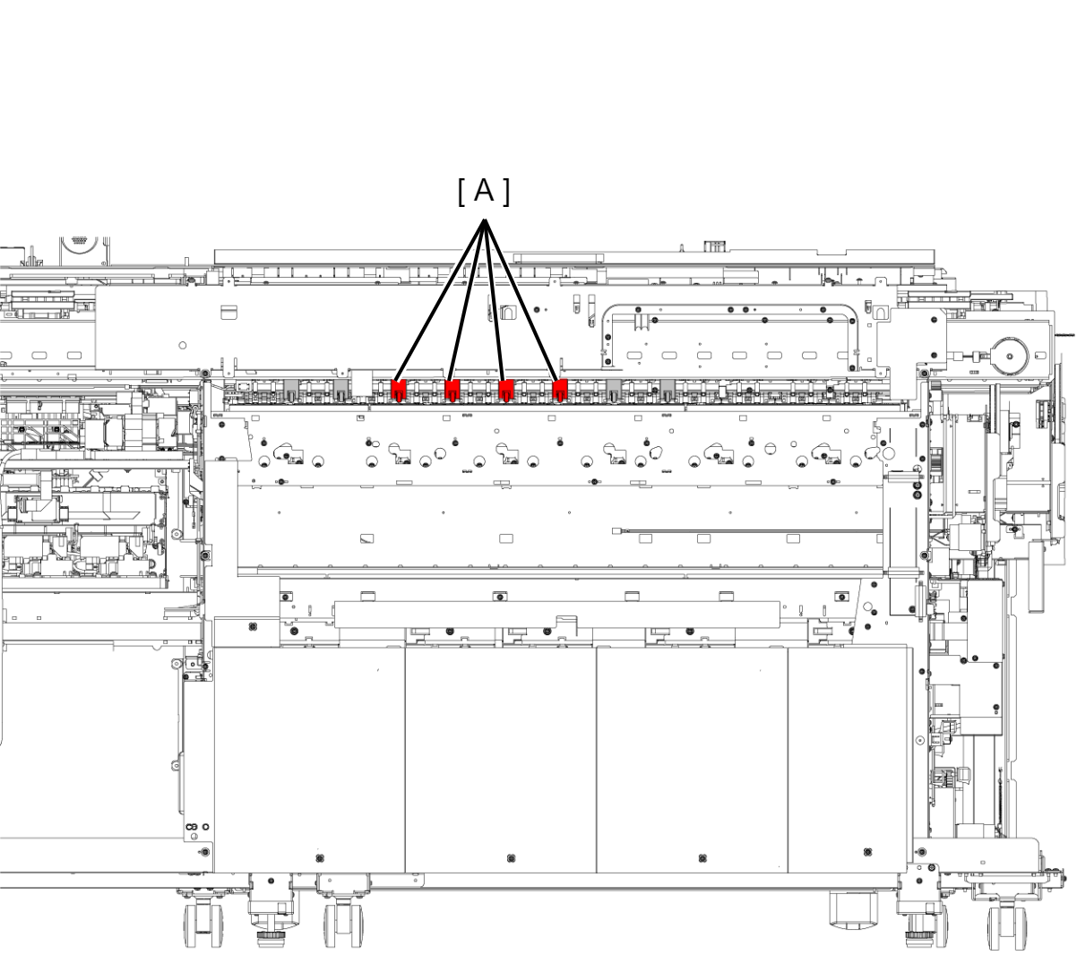
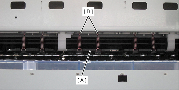
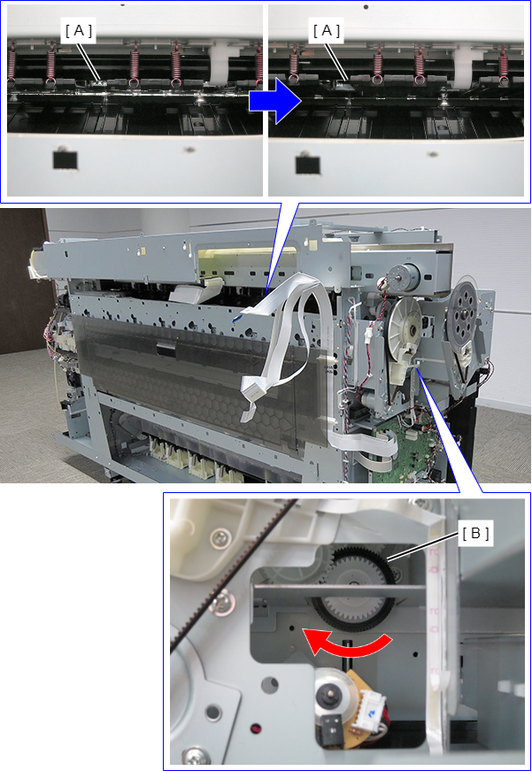
- Remove the two Tension Springs (B) from the Nip Release Roller (A) on the printer rear side.
Release nipping of the Nip Release Roller Unit.
Check Point / チェックポイントBefore starting work for removing the Nip Release Roller Unit, run the [Releasing Nip Release Roller] menu of the service program. When not using the service program, release nipping of the Nip Release Roller Unit by the following procedure.
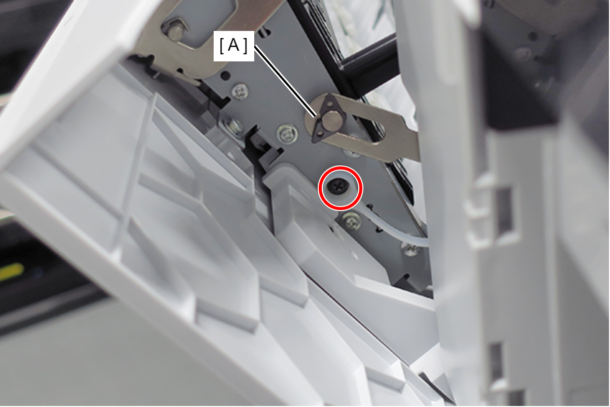
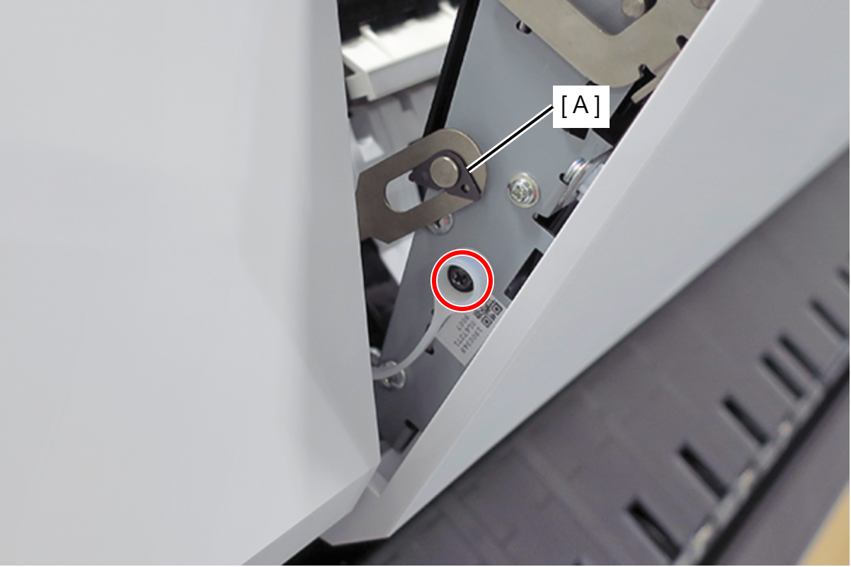
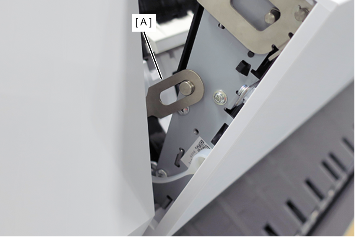
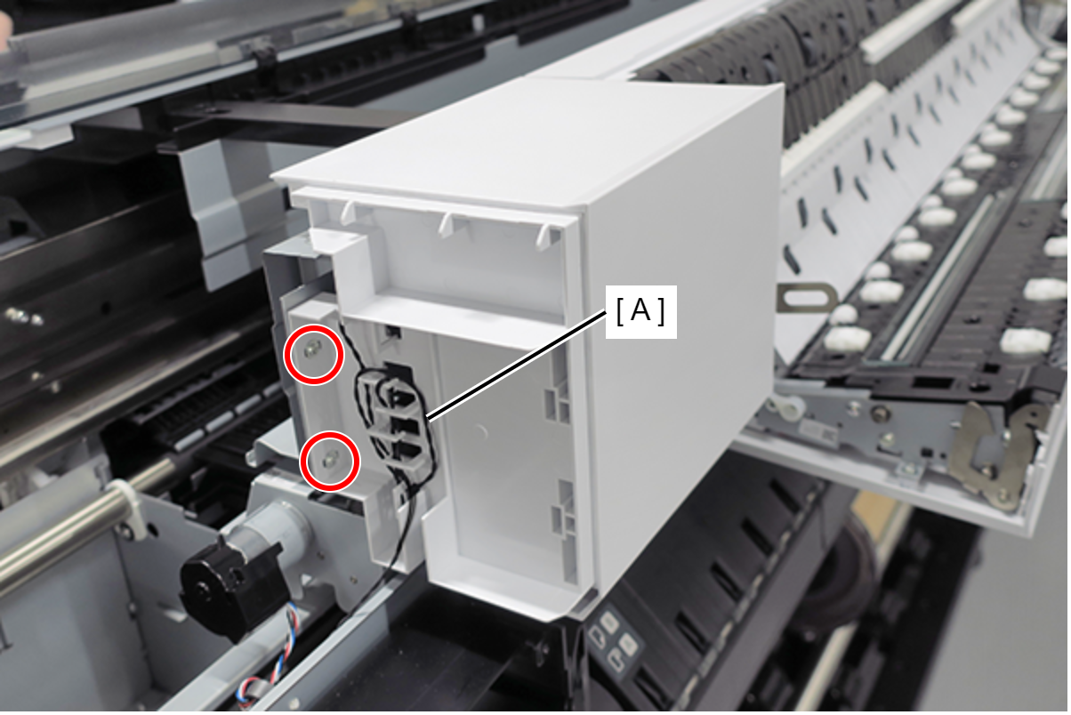
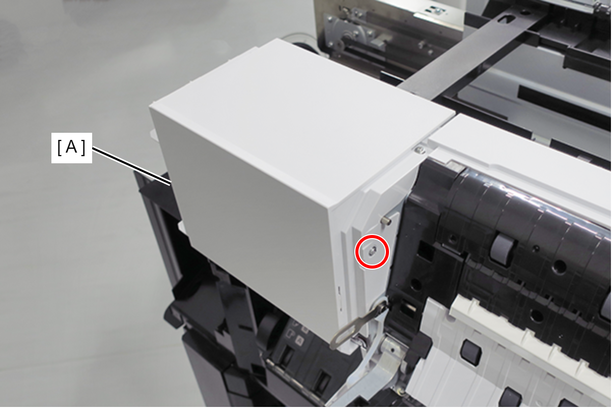
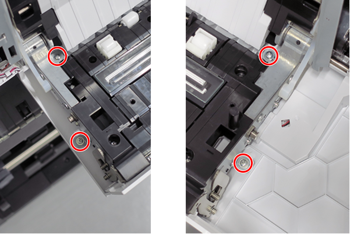
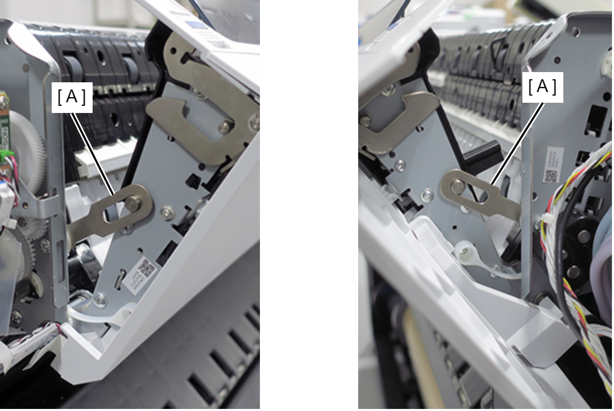
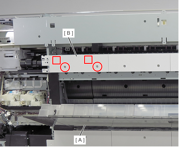
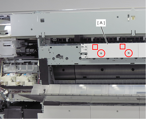
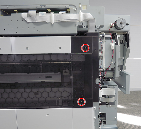
- Remove the 2 screws, then remove the ASF sub Motor Unit (A).
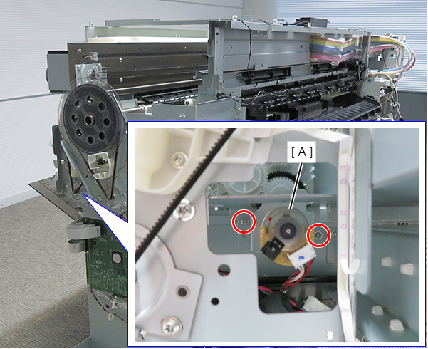
- : Silver M3x8 Cup S-tite screw
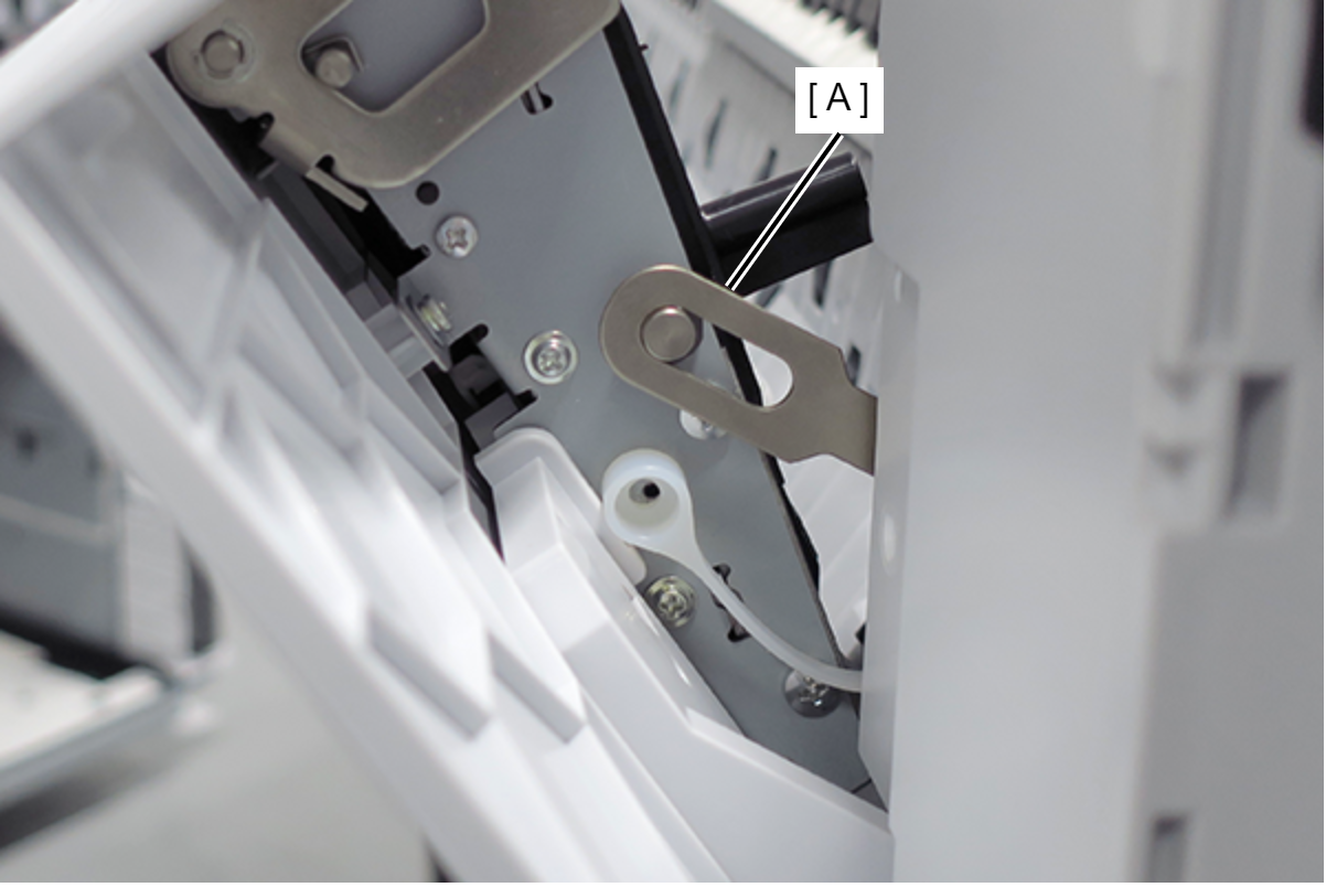
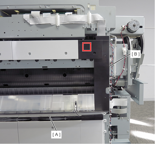
- Turn the clutch gear (B) clockwise until the Nip Release Roller Unit (A) move up.
- Remove the 2 screws, then remove the ASF sub Motor Unit (A).
- Disengage the two dowels of the Nip Release Roller Unit (A) using a flat-blade screwdriver or similar tool.
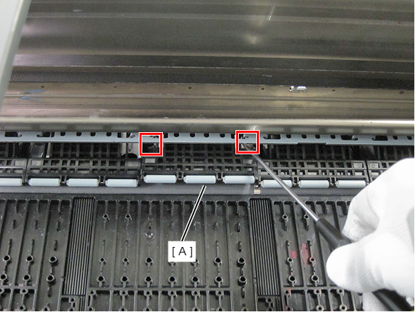
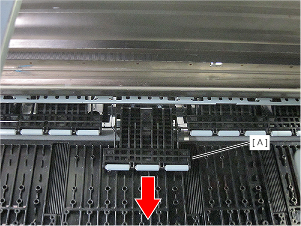
- Remove the Nip Release Roller Unit (A) toward you.
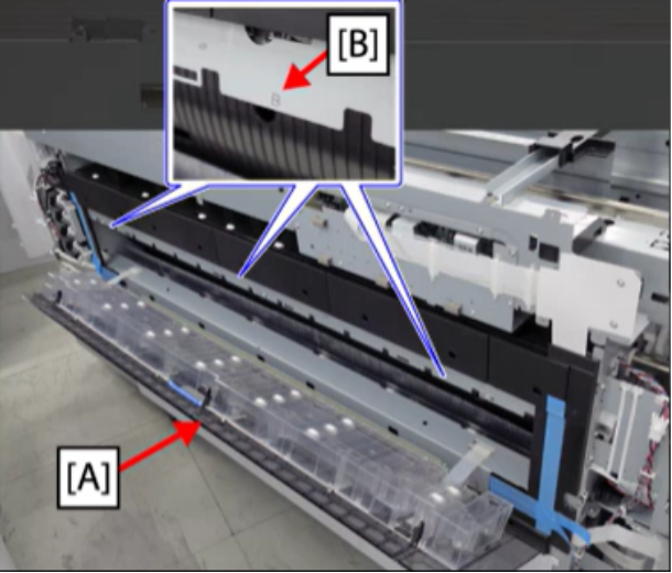
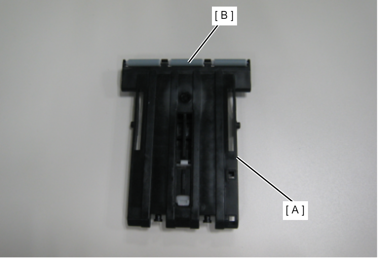
Remove the Nip Release Roller Holder (A) from the Nip Release Roller shaft (B).
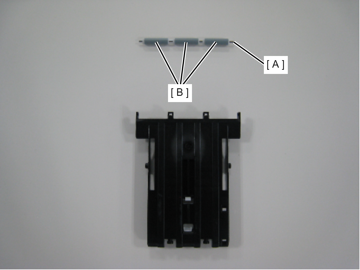
- Remove the Nip Release Roller (B) from the shaft (A).
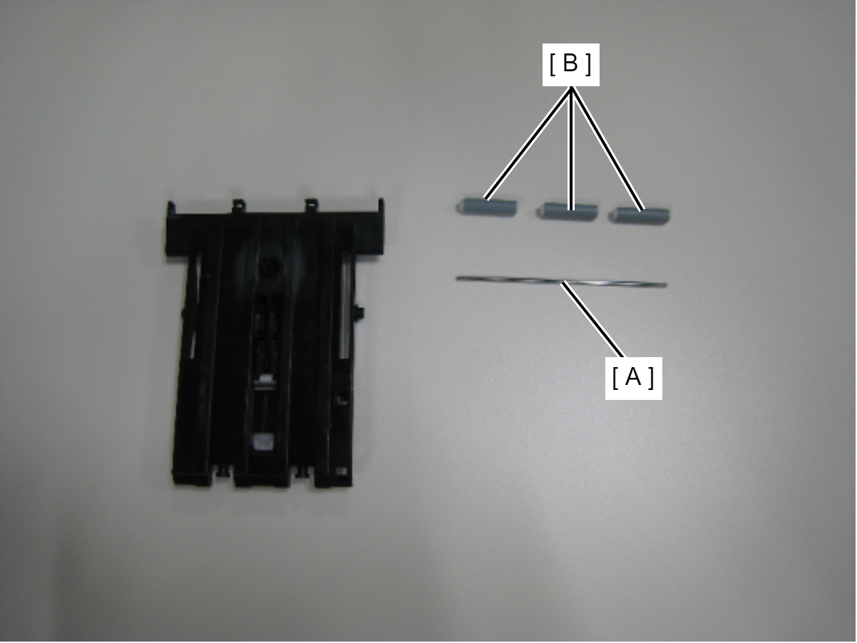
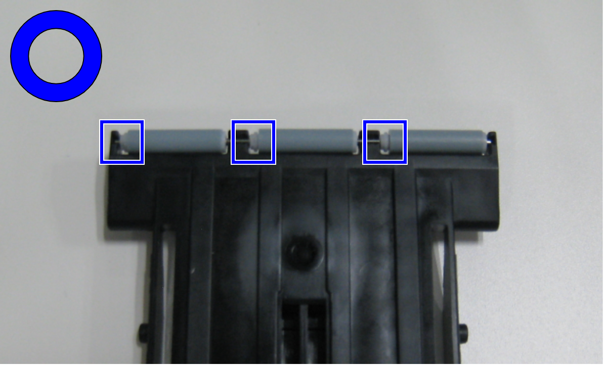
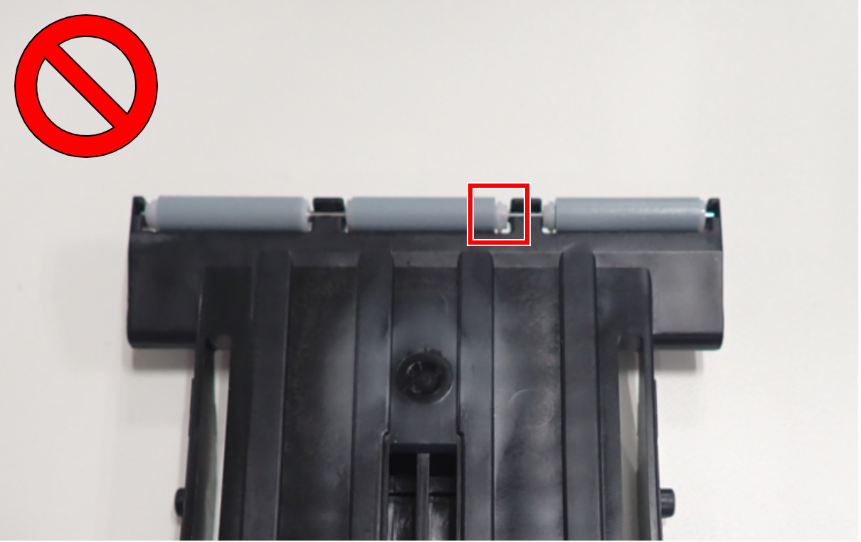
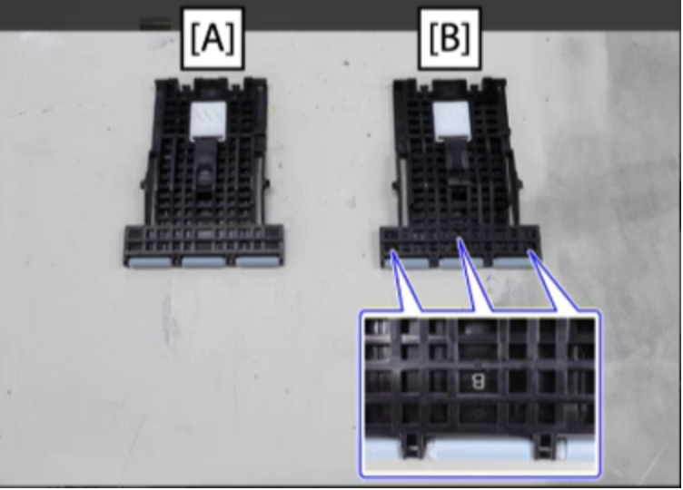
 Caution / 注意
Installing the Nip Release Roller in the opposite orientation means that during paper feed, the paper will have wrinkles, therefore make sure the orientation of the Nip Release Roller during installation is the same as for other rollers.