Head FFC Assy
 Adjustment / 調整 Adjustment / 調整 |
When replacing/removing this part, refer to the following pages and make sure to perform the required operations before assembly/reassembly. |
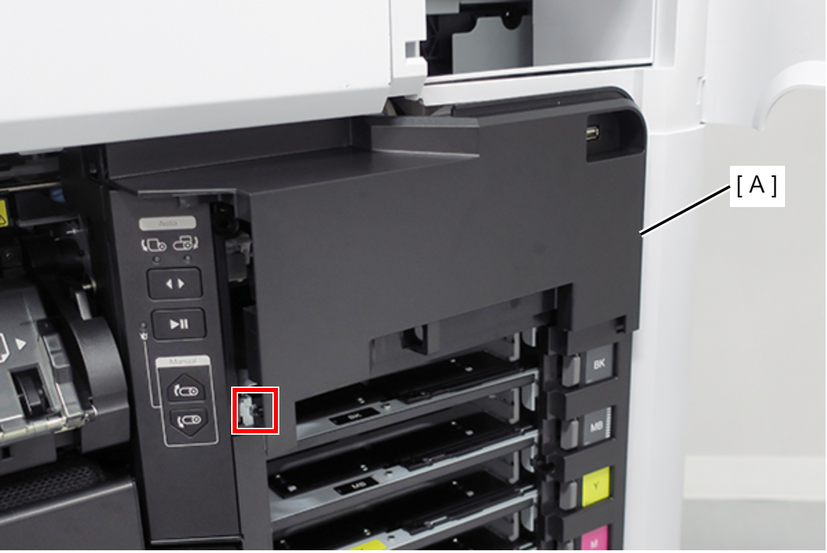
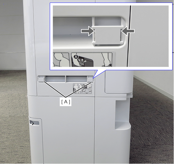
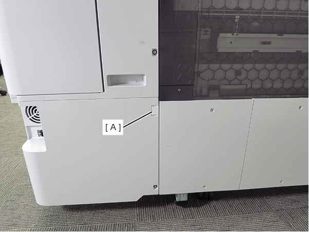
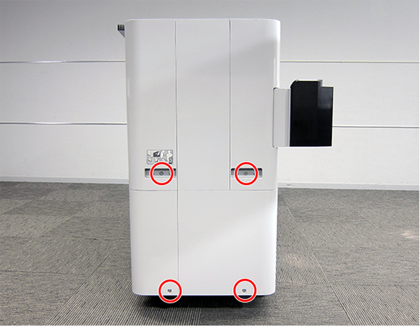
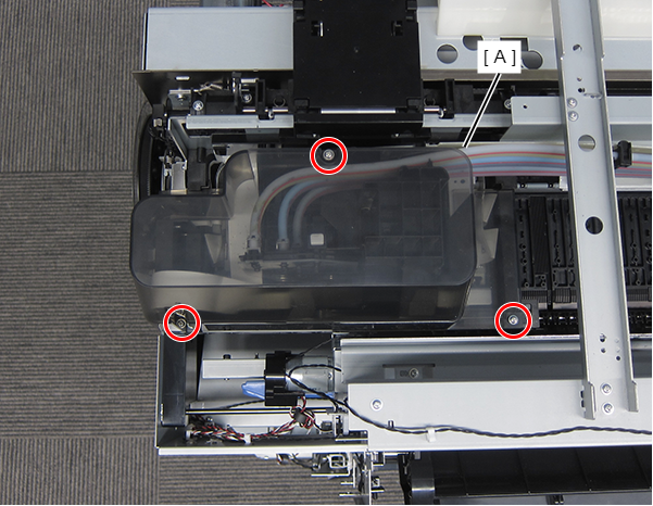
- Remove the single screw and remove the cover (A).
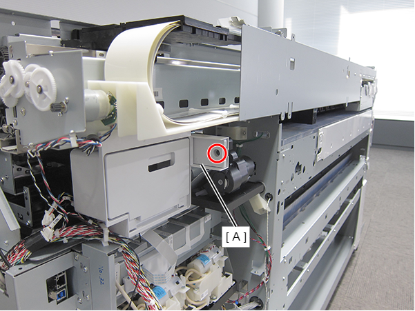
 : Silver M3x10 Cup P-tite screw
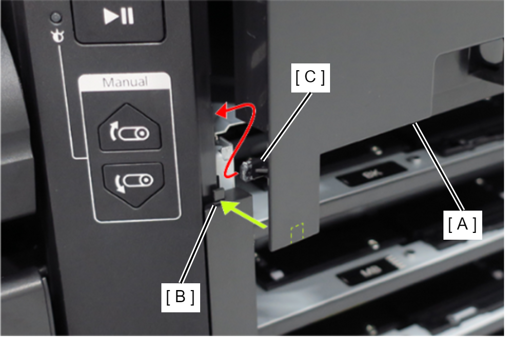
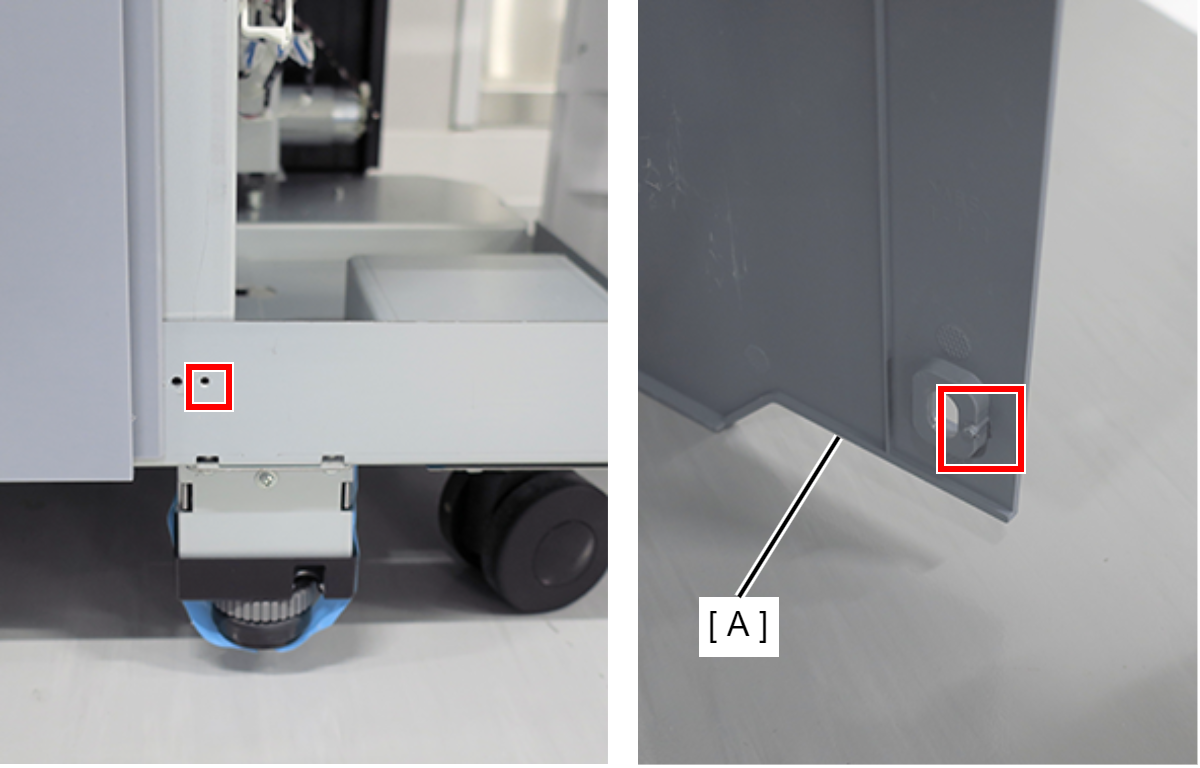
- Insert a screwdriver and rotate the CR Manual Unlock Gear (A) counter-clockwise.
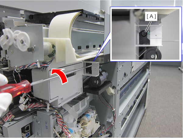
CR locked state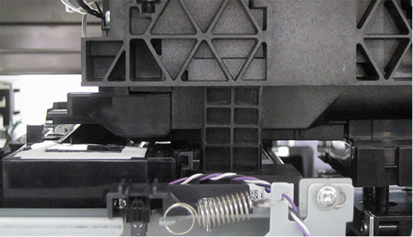
CR unlocked state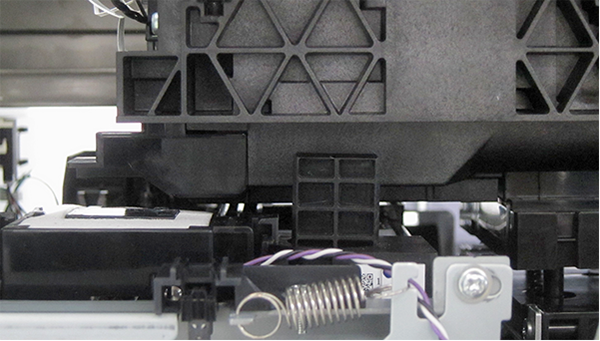
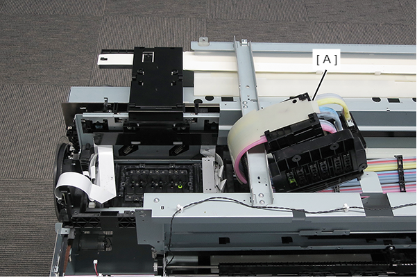
- Move the CR Unit (A) to the Full side.
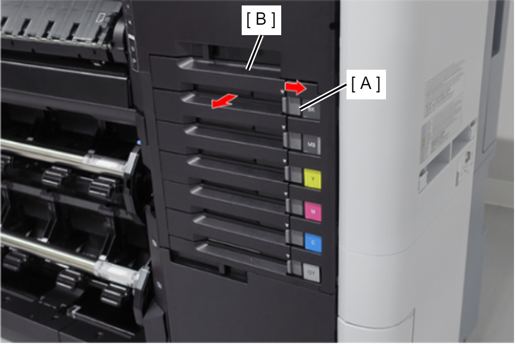
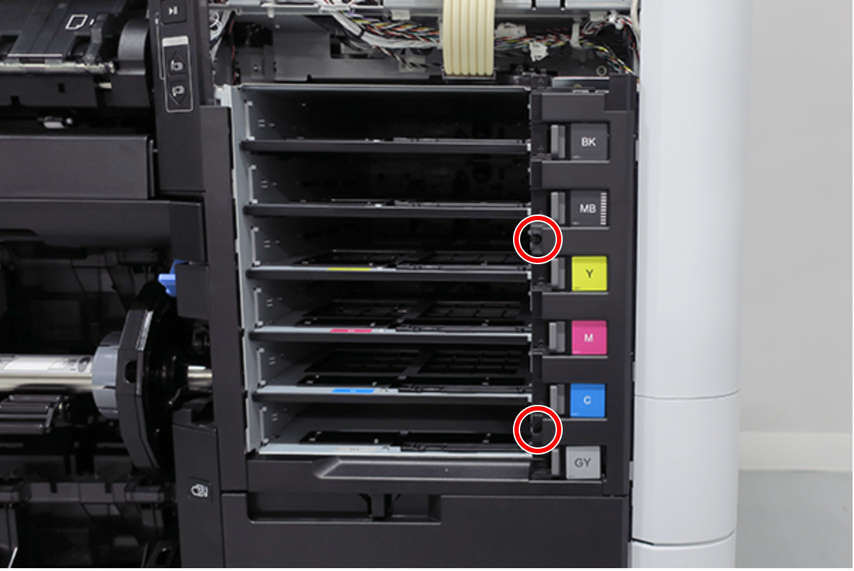
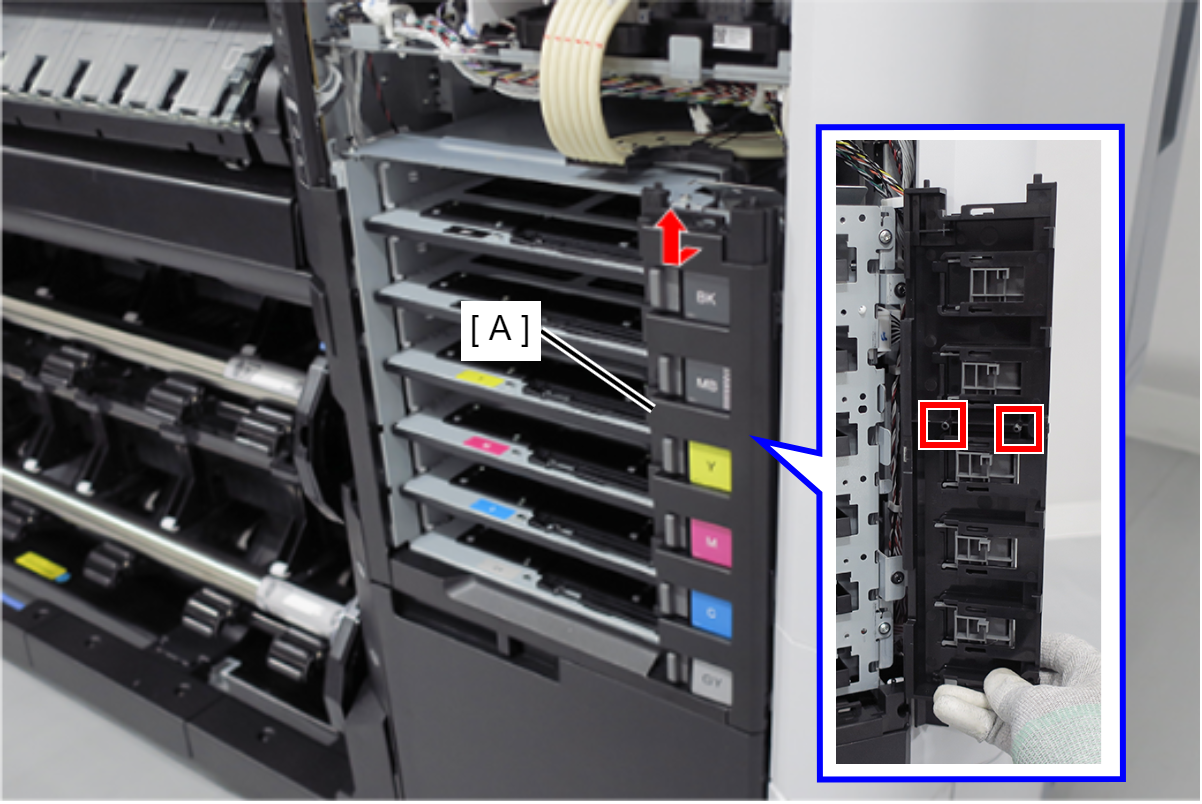
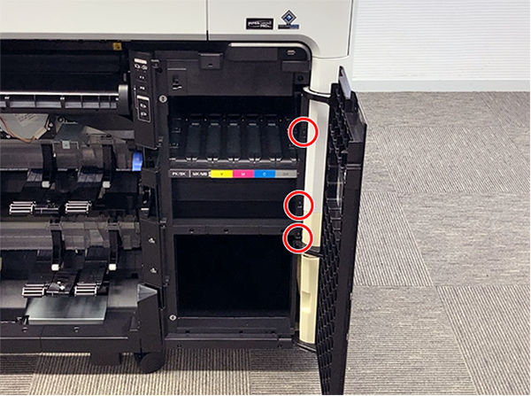
- Release the 6 locks (A), and remove the 6 Ink Pack Trays (B). (Only perform for SC-P8500DL series/SC-T7700DL series)
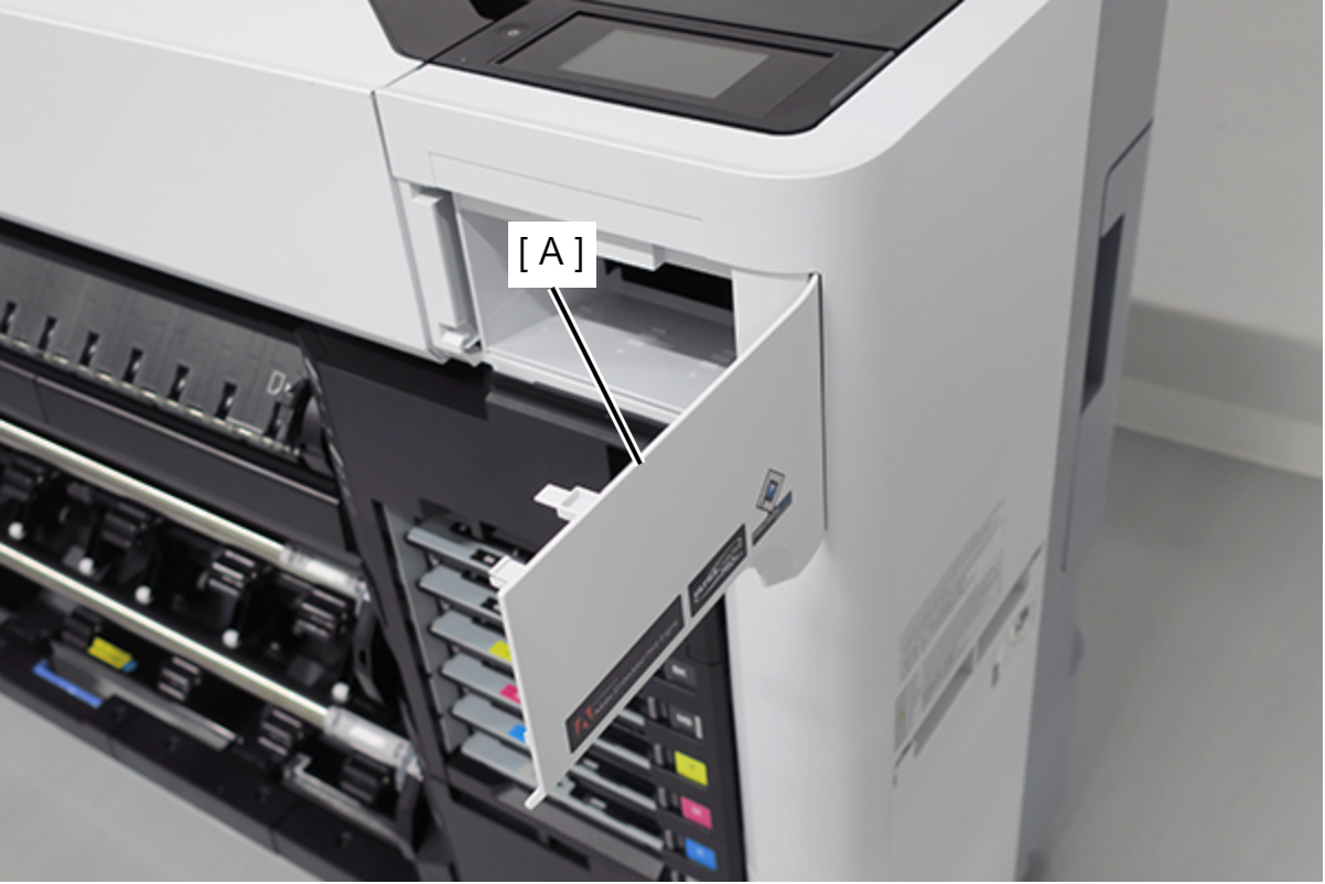
Open the Maintenance Cover (A). (Only perform for SC-P8500DL series/SC-T7700DL series)
- Remove the screw. (Only perform for SC-P8500DL series/SC-T7700DL series)
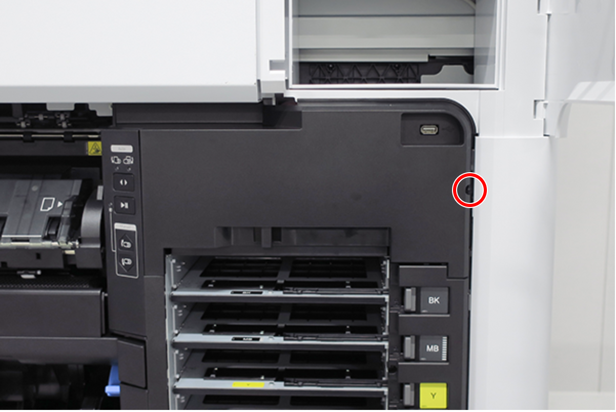
- :Black M3x8 S-tite screw
Release the hook, and remove the Ink Holder (RIPS) Upper Cover (A). (Only perform for SC-P8500DL series/SC-T7700DL series)
 Assembly / 組み立て
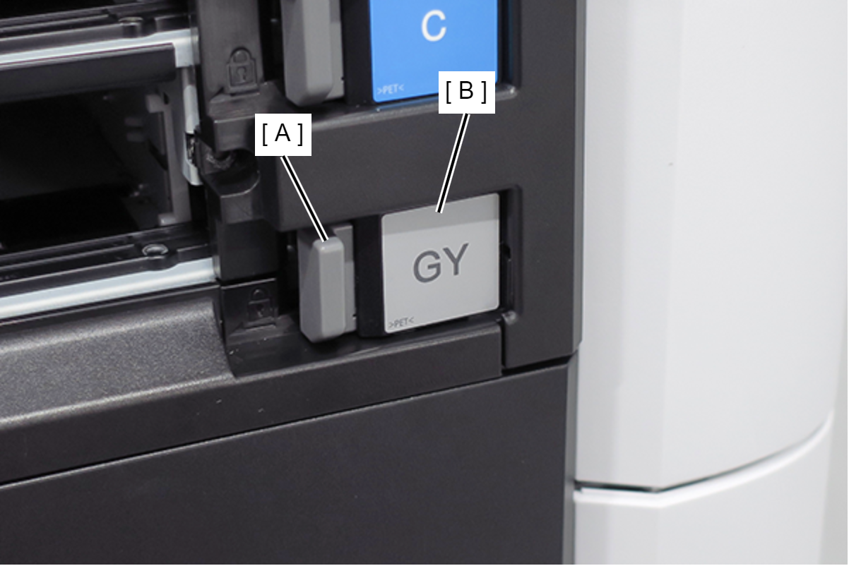
- Insert the Ink Holder (RIPS) Upper Cover (A) tab (B).
- Insert the Ink Holder (RIPS) Upper Cover (A) hook (C).
Remove the two screws, and remove the USB cable (A). (Only perform for SC-P8500DL series/SC-T7700DL series)
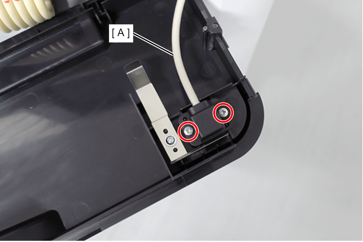
- : Silver M3x8 P-tite screw
Remove the two screws. (Only perform for SC-P8500DL series/SC-T7700DL series)
- : Silver M3x8 S-tite screw
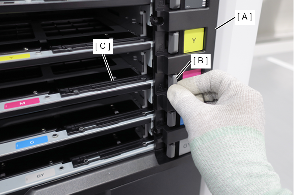
- Pull the Ink Pack Tray Right Side (A) slightly forward and release the 2 dowels. (Only perform for SC-P8500DL series/SC-T7700DL series)
Slide the Ink Pack Tray Right Side (A) upwards to remove. (Only perform for SC-P8500DL series/SC-T7700DL series)
 Assembly / 組み立て
- The gray lock lever (A) and ink plate (B) will come off when removing the Ink Pack Tray Right Side (C). Install them after installing the Ink Pack Tray Right Side (C) in the main unit.
- With the lock lever (A) and tray lever (B) moved to the right side, install the Ink Pack Tray Right Side (C).
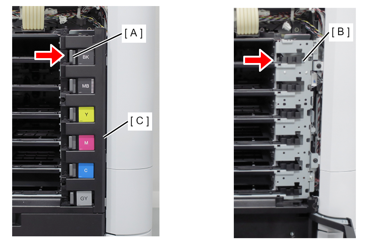
- After installing the Ink Pack Tray Right Side (A), move the lock lever (B) and confirm that the tray lever (C) moves in conjunction.
- The gray lock lever (A) and ink plate (B) will come off when removing the Ink Pack Tray Right Side (C). Install them after installing the Ink Pack Tray Right Side (C) in the main unit.
- Open the Maintenance Box Cover (A).
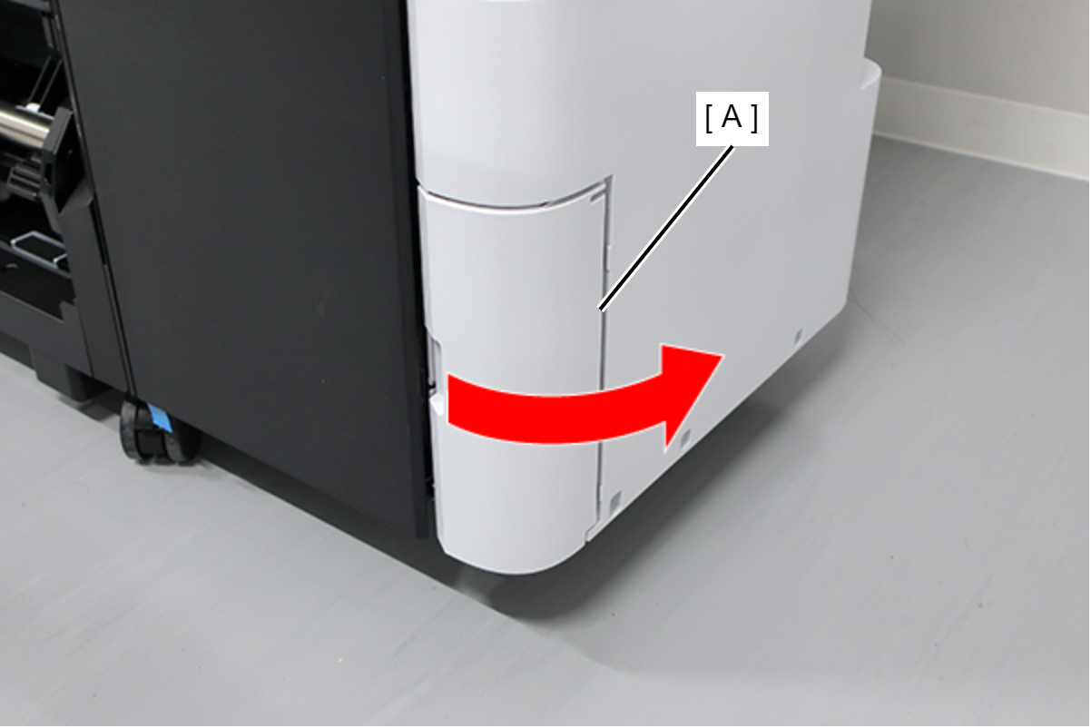
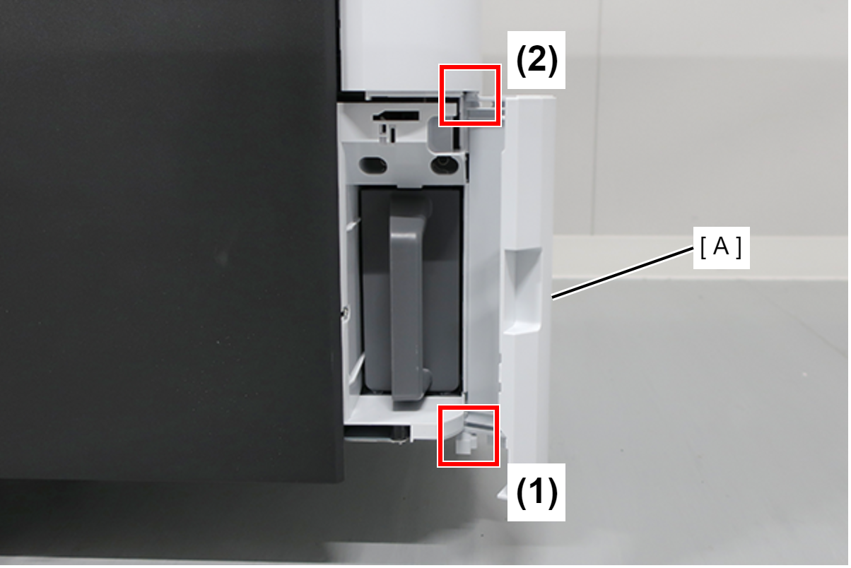
- Release the 2 tabs of the Maintenance Box Cover (A) in the order shown in the figure below, and remove.
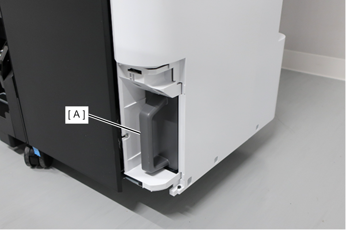
- Remove the Maintenance Box (A).
- Remove the screw.
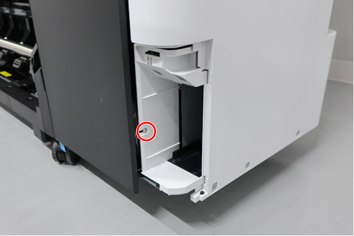
- : : Silver M3x8 Cup S-tite screw
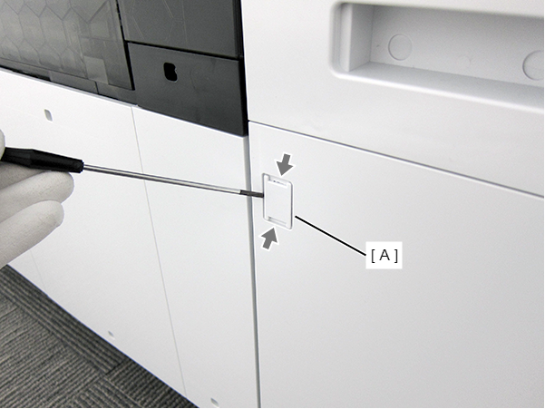
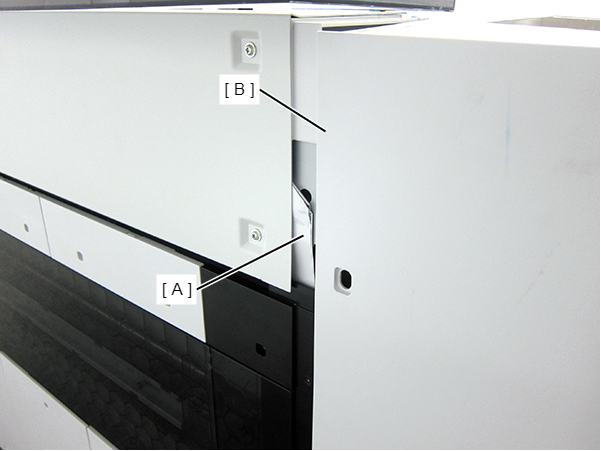
- Insert a flathead screwdriver and release the 2 hooks each, and remove the two screw cover (A).
- Insert a flathead screwdriver and release the 2 hooks, and remove the screw cover (A).
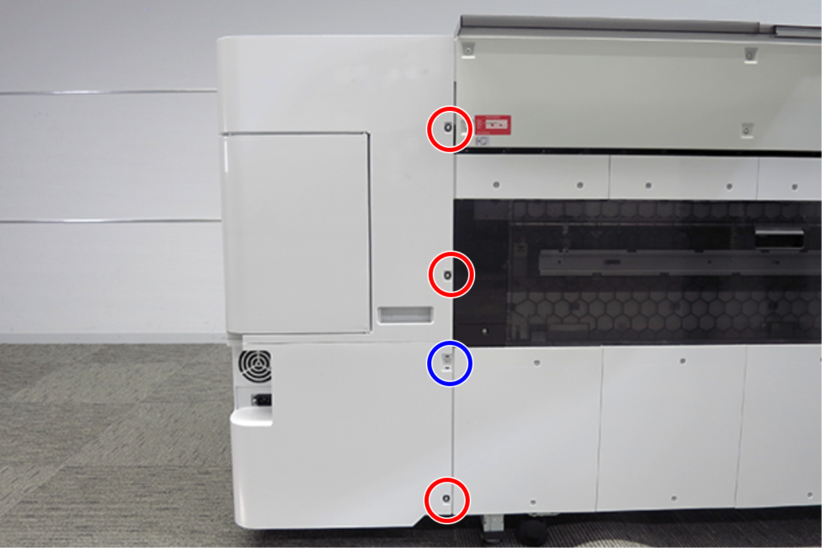
- Remove the three screws at the front side.
- : Black M3x8 Cup P-tite screw
- Remove the five screws at the right side.
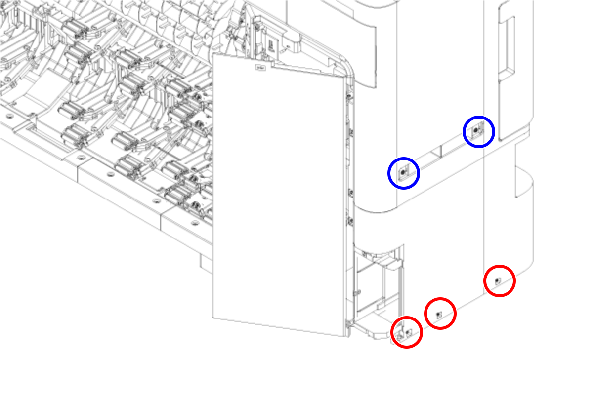
- : Silver M3x8 Cup S-tite screw
 : Silver/M4x8/machine screw
- Remove the four screws at the rear side.
- : Silver M3x8 Cup S-tite screw with plastic washer
- : : Silver M3x8 Cup S-tite screw
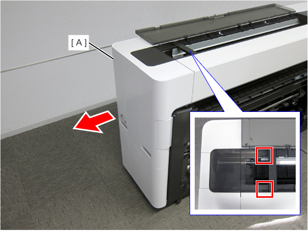
- On the printer rear side, release the dowel of the Home Side Cover Unit (A).
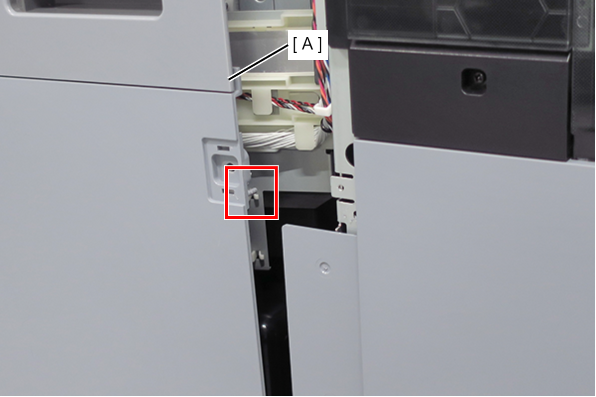
- Insert a flathead screwdriver and release the 2 tabs each, and remove the Home Side Cover Unit (A) in the direction of the arrow.
- Insert a flathead screwdriver and release the two hooks, and remove the screw cover (A).
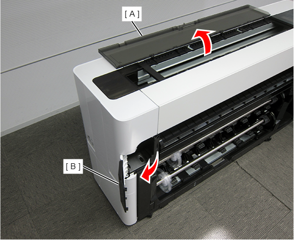
- Open the Printer Cover (A) and the Cutter Cover (B).
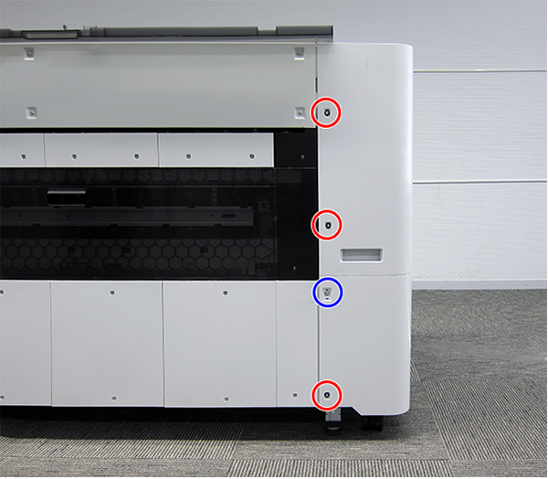
- Remove the three screws at the front side.
- : Silver M3x10 Cup P-tite screw
- : : Silver M3x8 Cup S-tite screw
- Remove the screw at the top side.
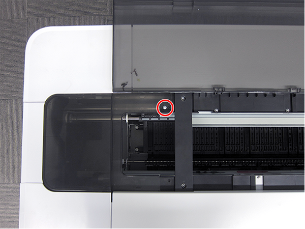
- : : Silver M3x8 Cup S-tite screw
- Remove the four screws at the rear side.
- : Silver M3x8 Cup S-tite screw with plastic washer
- : : Silver M3x8 Cup S-tite screw
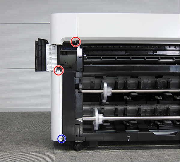
- Remove the four screws at the left side.
- : Silver M3x8 Cup S-tite screw
- : Silver/M4x8/machine screw
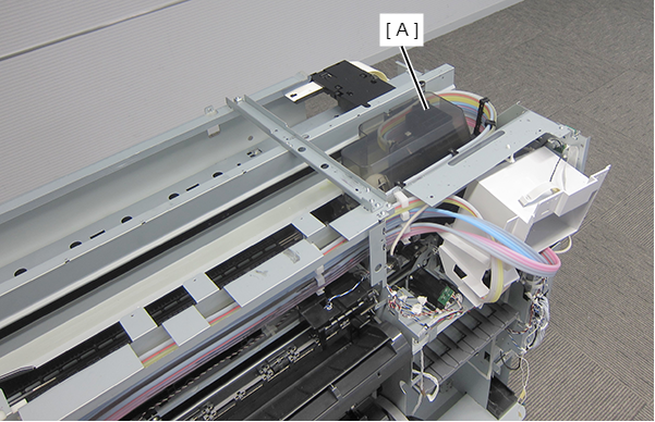
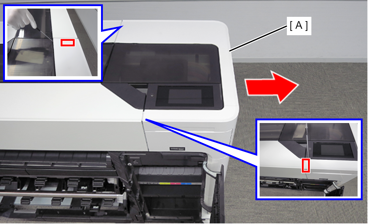
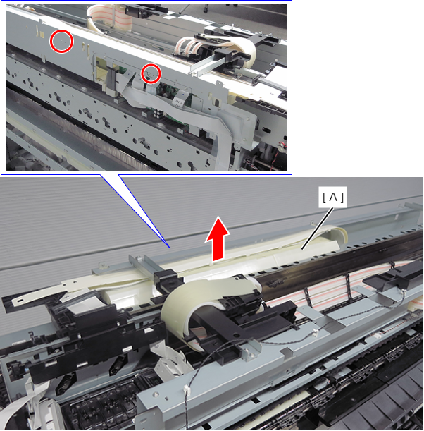
On the printer rear side, release the dowel of the Full Side Cover Unit (A).
Remove the Full Side Cover Unit (A) from the dowels, and remove it while it in the direction of the arrow.
 Assemble / 組み立て
When installing the Full Side Cover Unit (B), carefully the Head FFC (A) so that it does not damage.
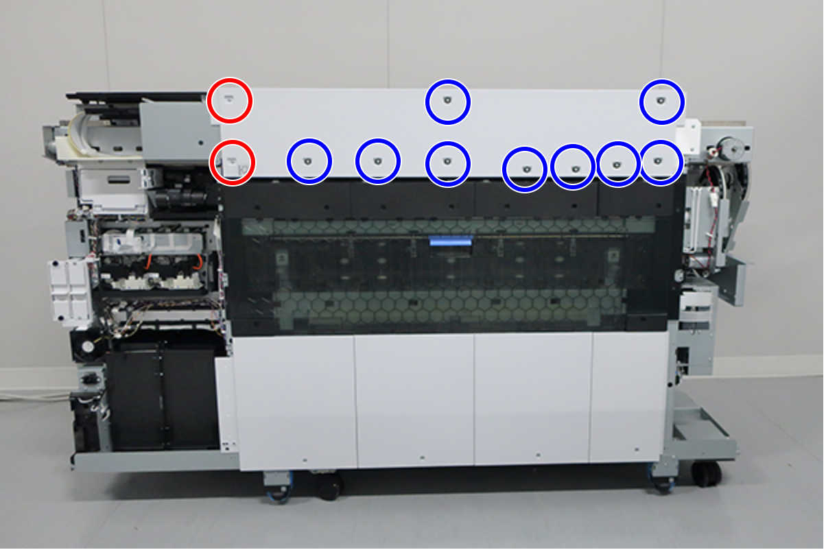
- Remove the screws on the top.
SC-P8500D series/SC-T7700D series/SC-P8500DL series/SC-T7700DL series/SC-P8500DM series/SC-T7700DM series: 8 pcs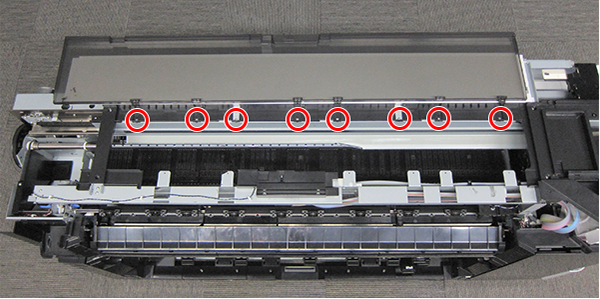
- : Silver M3x8 Cup S-tite screw
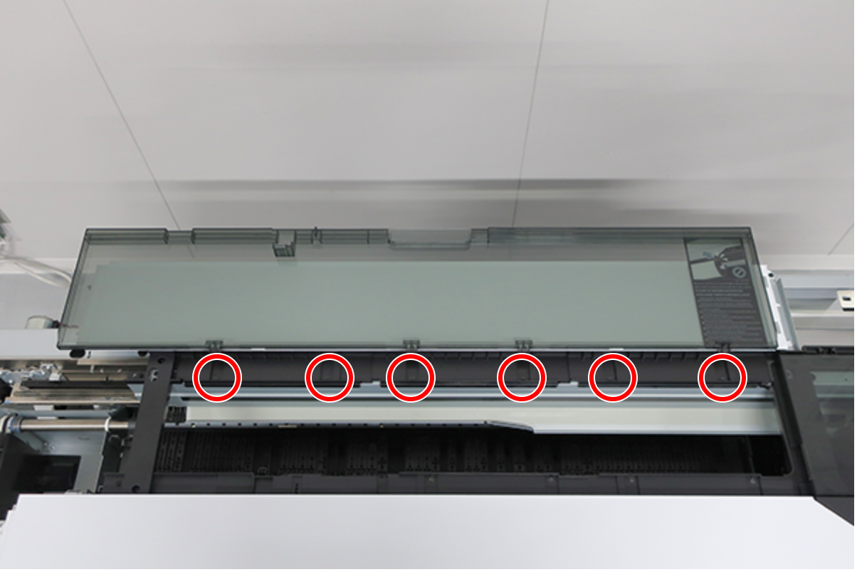
- : Silver M3x8 Cup S-tite screw
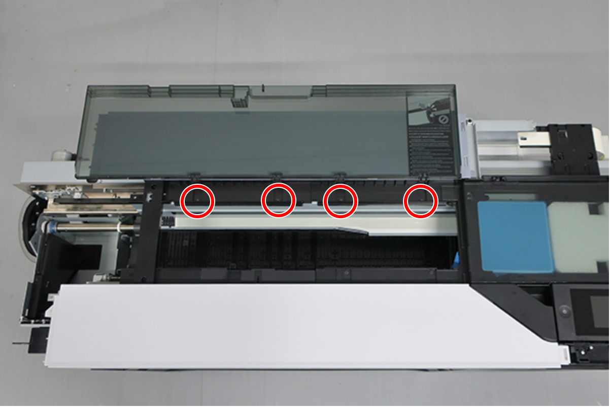
- : Silver M3x8 Cup S-tite screw
- Remove the screws on the back.
SC-P8500D series/SC-T7700D series/SC-P8500DL series/SC-T7700DL series/SC-P8500DM series/SC-T7700DM series: 6 pcs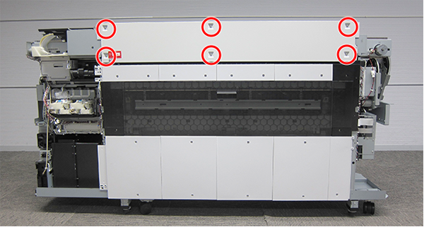
- : Silver M3x8 Cup S-tite screw
- : Silver M3x8 Cup S-tite screw
- : Silver M3x8 Cup S-tite screw with plastic washer
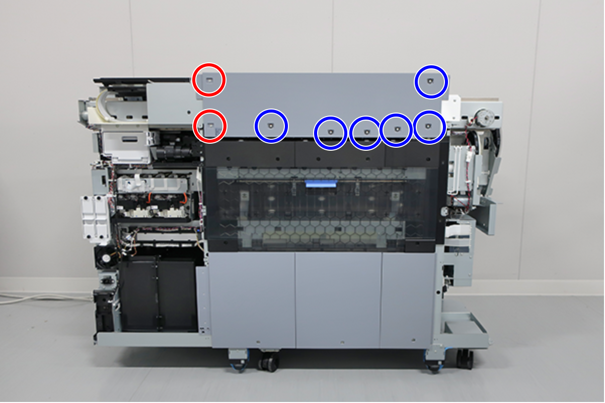
- : Silver M3x8 Cup S-tite screw
 : Silver M3x8 Cup S-tite screw with plastic washer
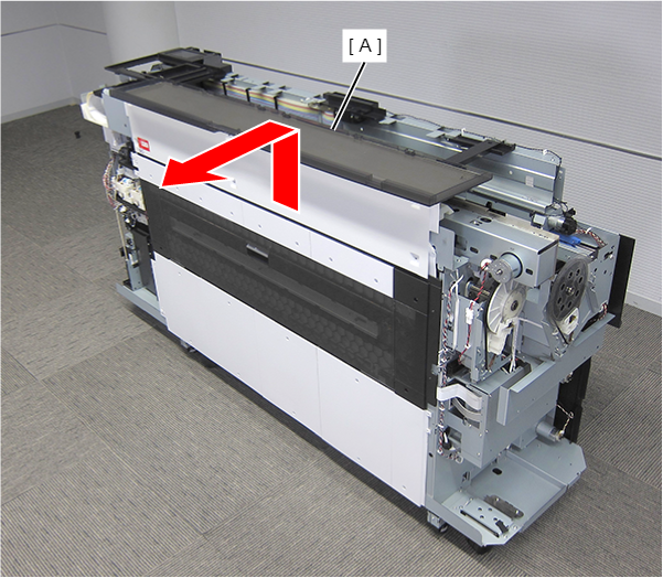
- Remove the Printer Cover Unit backward.
- Remove the 2 FFC Clamps (A).
- Remove the 7 screws and then remove the plate (B).
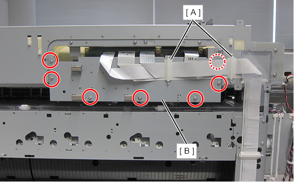
- : Silver M3x8 Cup S-tite screw
- Move the CR Unit to the Full side.
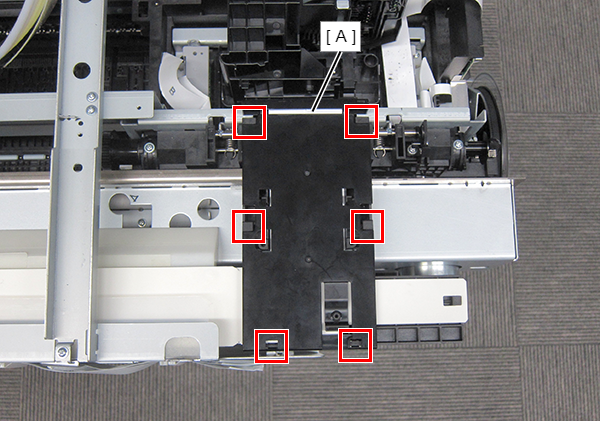
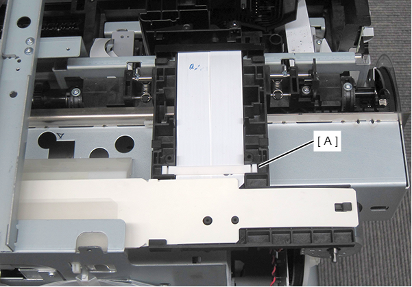
- Remove the three screws and remove the CR Cover (A).
- : Silver M3x8 Cup S-tite screw
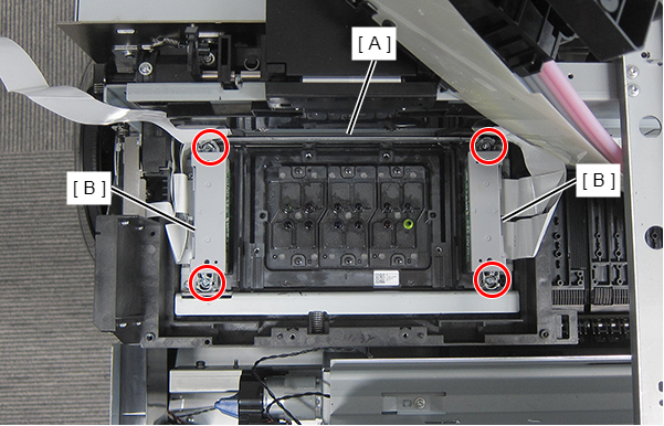
Remove the six screws.
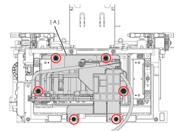
- : Silver M3x8 Cup S-tite screw
 Caution / 注意
If the Ink Tube is removed by the procedure described below, ink may flow down the tube. Therefore, keep rags handy in advance to prevent the surroundings from getting soiled.
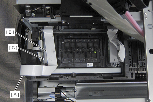
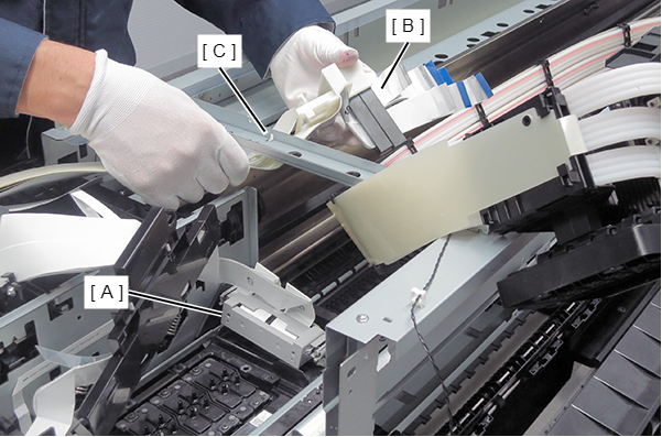
- Temporarily place the Self Sealing Valve Assy and the tube stopper (A) as shown below.
Lift up the tab, and remove the Head FFC Connector Clamp (A) in the direction of the arrow.
 Assemble / 組み立て
Insert the 6 Head FFC Clamp (A) tabs into the CR Unit positioning holes.
- Remove the Head FFC Control Clamp (A).
- Remove the FFC (B) from the connector (A).
Remove the FFC (B) from Head FFC Assy (C).
Loosen the 4 screws.
- : Silver M3x22 S-tite screw with built-in washer
 Check Point / チェックポイント
The four screws that secure the Print Head are designed not to be removed easily to prevent dropping and losing them.
- Detach the FFC protection sheets from the four positioning points.
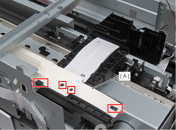
- Remove the 2 screws, and then remove the FFC Holder (A) upward.
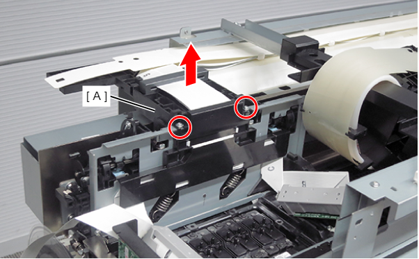
- : : Silver M3x8 Cup S-tite screw
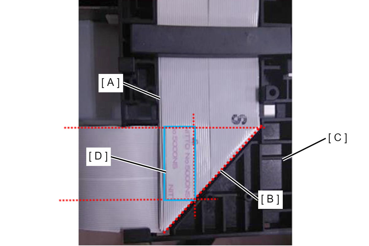
Assembly / 組み立て- With the fold (B) of the Head FFC Assy (A) aligned with the position in the CR Unit (C) as shown in the figure below, attach the Head FFC Assy (A) using double-sided tape (D).
- When installing the FFC holder (A), push the five tabs of the FFC holder (A) into the CR Unit (B) positioning holes. If this is not adhered to, the FFC holder (A) will be scraped off while the CR Unit (B) is in operation, and the dust from this will fall into the CR Unit (B) operational path and may reduce print quality.
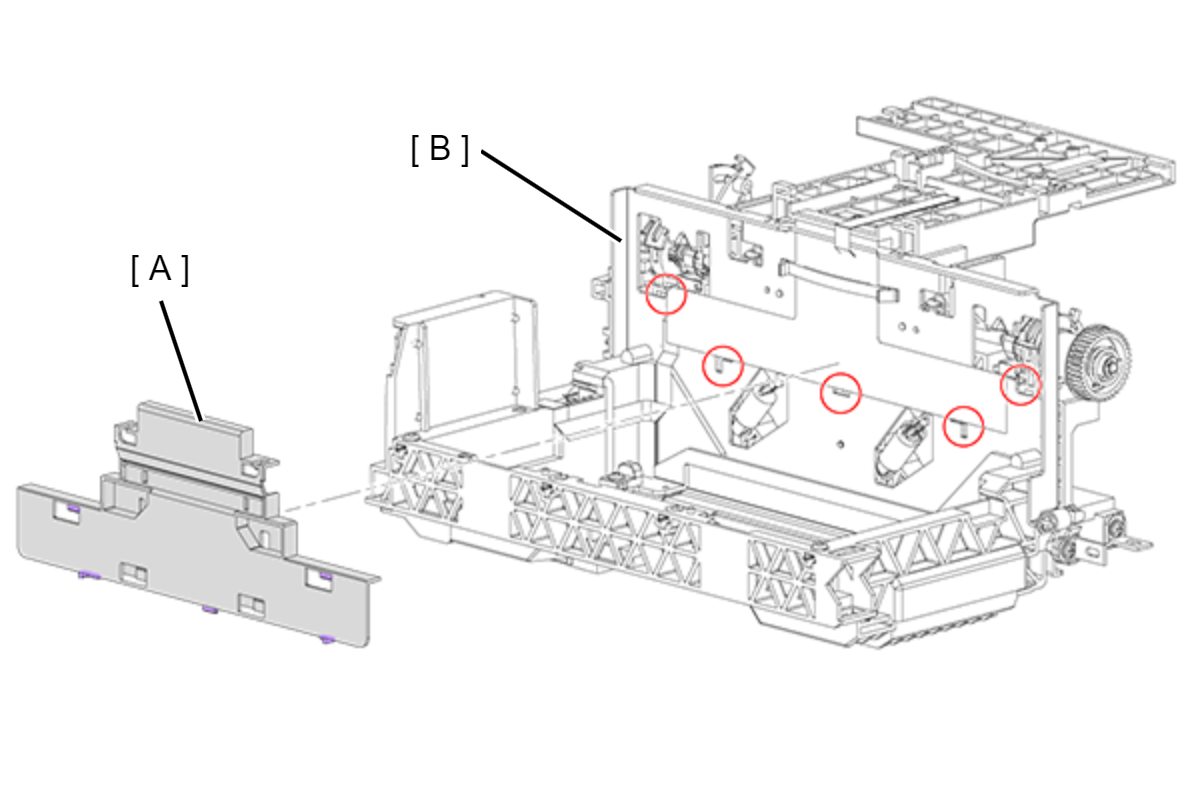
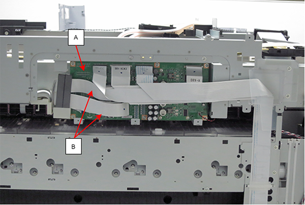
- Remove the two screws at rear side, and the remove the FFC cover while sliding.
- : Silver M3x10 Cup P-tite screw
- Remove the FFC (B) from the connectors (CN5, CN6, CN8, CN9, CN201, CN202, CN203 and CN204) of CH83 DRV-H Board (A).
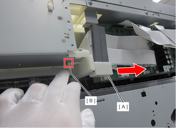
- Push down the lever of the FFC holder to disengage the dowel, and slide the FFC Holder to detach it.
- Remove the Head FFC Assy upward.
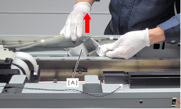
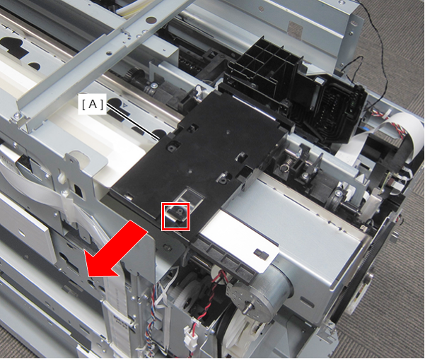
- Move the CR Unit (A) to the Full side.
Remove the Head FFC Assy (B) through the gap between the frame (C) and the CR Unit (A).
Head FFC Assy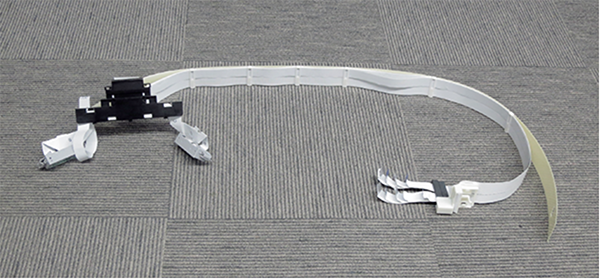 Assembly / 組み立て
Check that the Head FFC and the end face of the CR Unit are not in contact.
| Adjustment / 調整 |
When replacing/removing this part, refer to the following pages and make sure to perform the specified operations including required adjustment. |