CH83 Main-B Circuit Board
 Caution / 注意 Caution / 注意 |
When performing repair work on an exposed board, wait at least 30 seconds after turning off the power before starting repair work. If work is started while voltage remains, the following operations may damage the board.
|
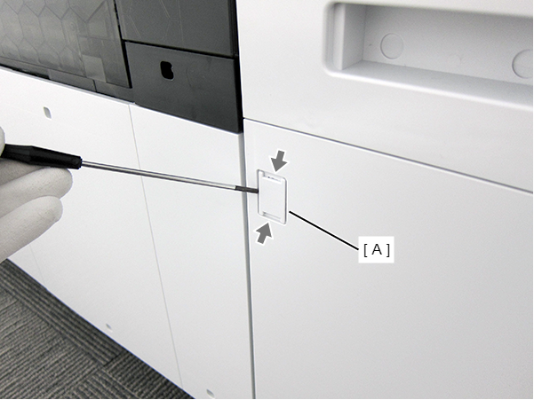
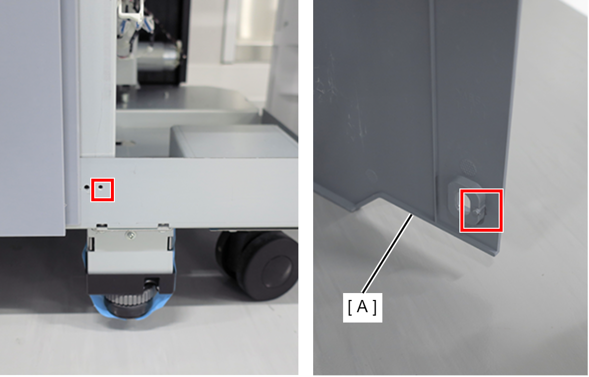
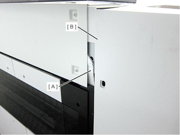
- Insert a flathead screwdriver and release the two hooks, and remove the screw cover (A).
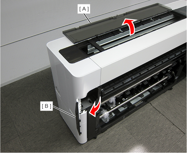
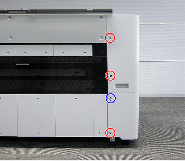
- Open the Printer Cover (A) and the Cutter Cover (B).
- Remove the three screws at the front side.
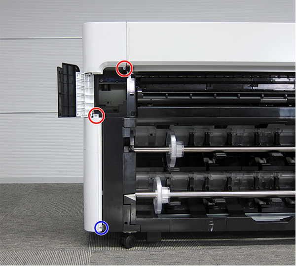
 : Silver M3x10 Cup P-tite screw
 : : Silver M3x8 Cup S-tite screw
- Remove the screw at the top side.
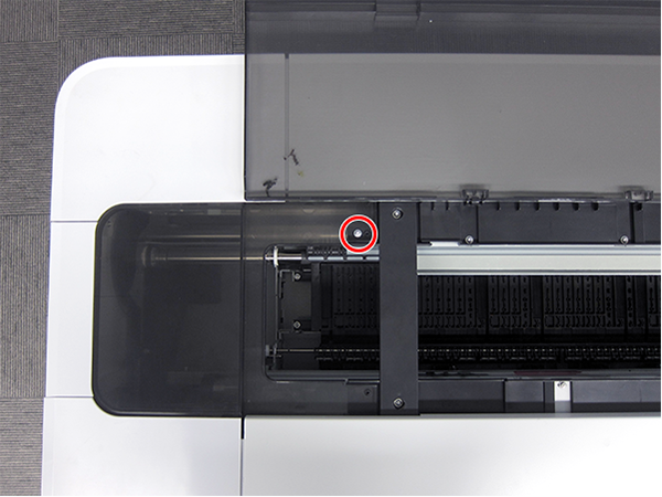
- : : Silver M3x8 Cup S-tite screw
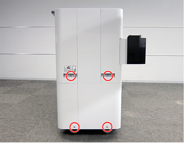
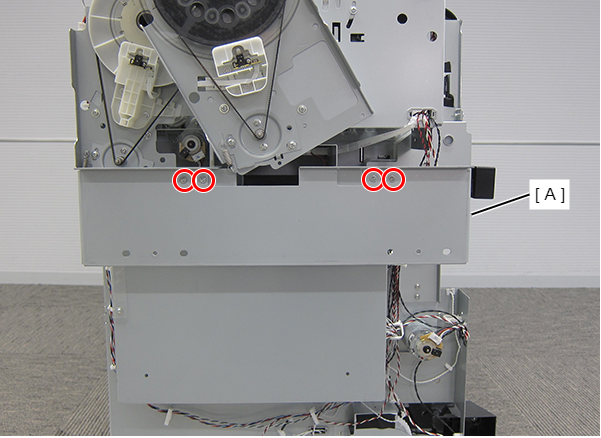
- Remove the four screws at the rear side.
- : Silver M3x8 Cup S-tite screw with plastic washer
- : : Silver M3x8 Cup S-tite screw
- Remove the four screws at the left side.
- : Silver M3x8 Cup S-tite screw
- : Silver/M4x8/machine screw
On the printer rear side, release the dowel of the Full Side Cover Unit (A).
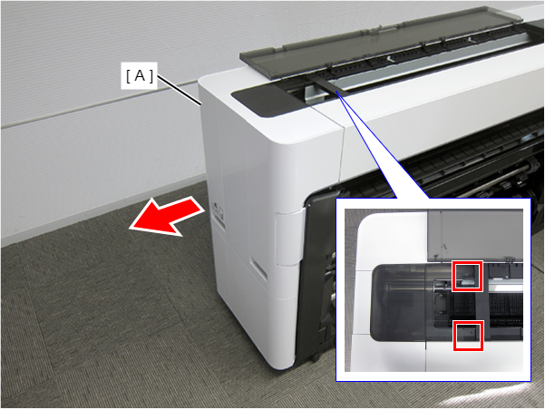
Remove the Full Side Cover Unit (A) from the dowels, and remove it while it in the direction of the arrow.
 Assemble / 組み立て
When installing the Full Side Cover Unit (B), carefully the Head FFC (A) so that it does not damage.
- Remove the four screws and then remove the Housing Support Plate.
- : Silver M3x8 Cup S-tite screw
- Remove the seven screws and then remove the CH83 Main-B Board Cover (A).
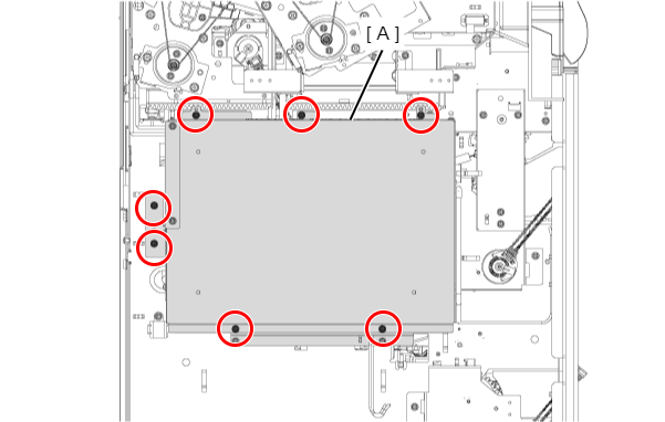
- : Silver M3x8 Cup S-tite screw
Assemble / 組み立てTake care that the cables do not get pinched.
- Release the connector locks (A) (CN20 and CN21) to remove the 2 sheets of FFC.
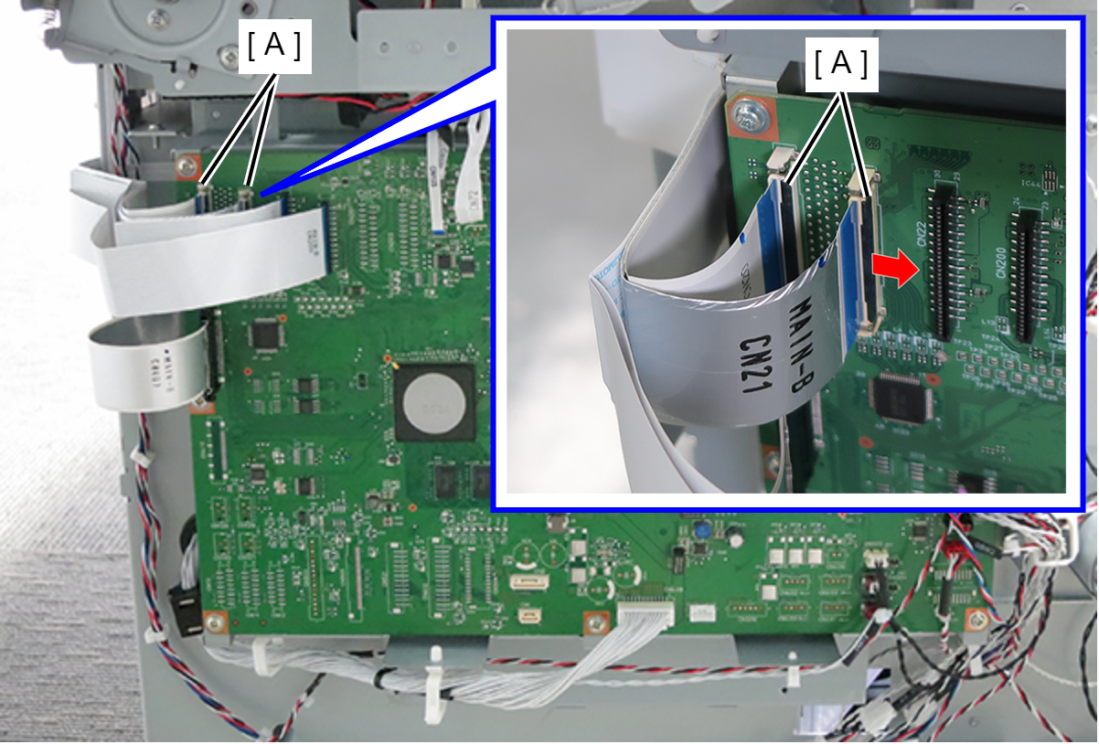
- Release the hook and then remove the cables (CN408, CN500, CN503, CN506 and CN522) from connector (A).
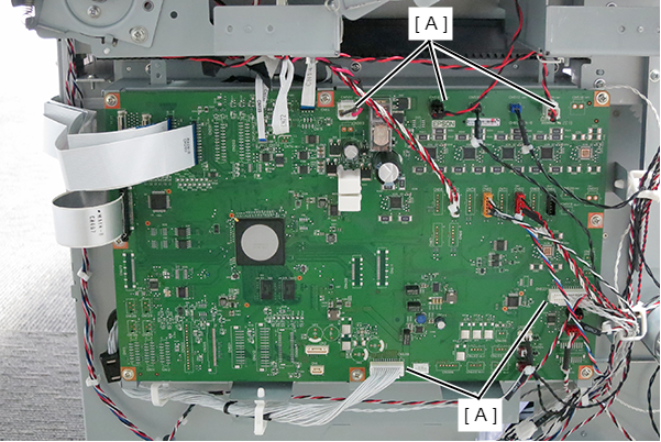
- Remove the remaining cables and the FFC connected to the Main Board B.
- Remove the 8 screws and then remove the Main Board B 8.
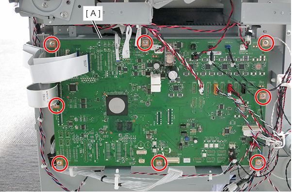
- : Silver M3x8 Cup S-tite screw
 Adjustment / 調整 Adjustment / 調整 |
When removing/replacing this part, refer to following page and make sure to perform the specified operations including required adjustment. |