Panel FFC Assy
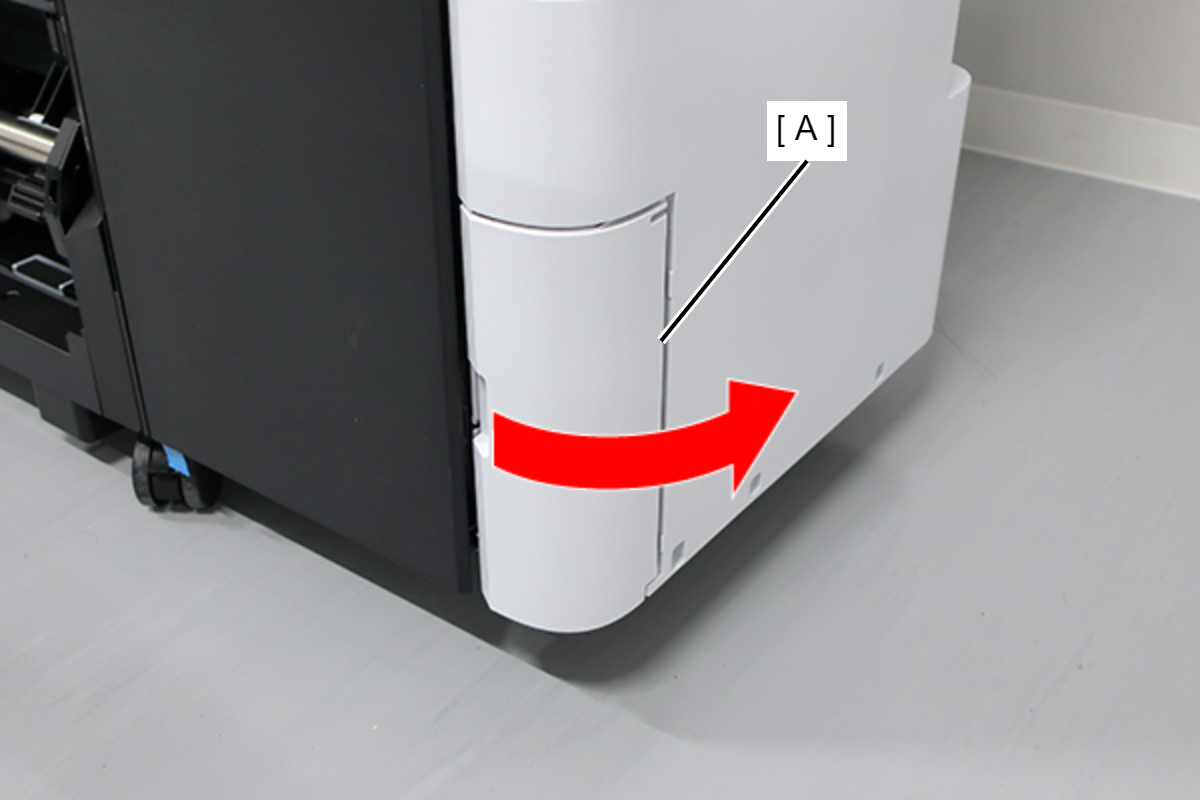
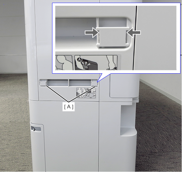
- Open the Maintenance Box Cover (A).
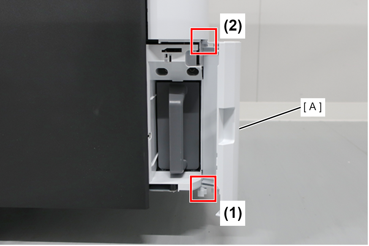
- Release the 2 tabs of the Maintenance Box Cover (A) in the order shown in the figure below, and remove.
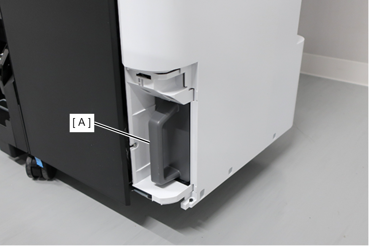
- Remove the Maintenance Box (A).
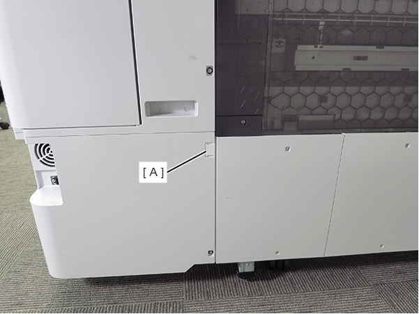
- Remove the screw.
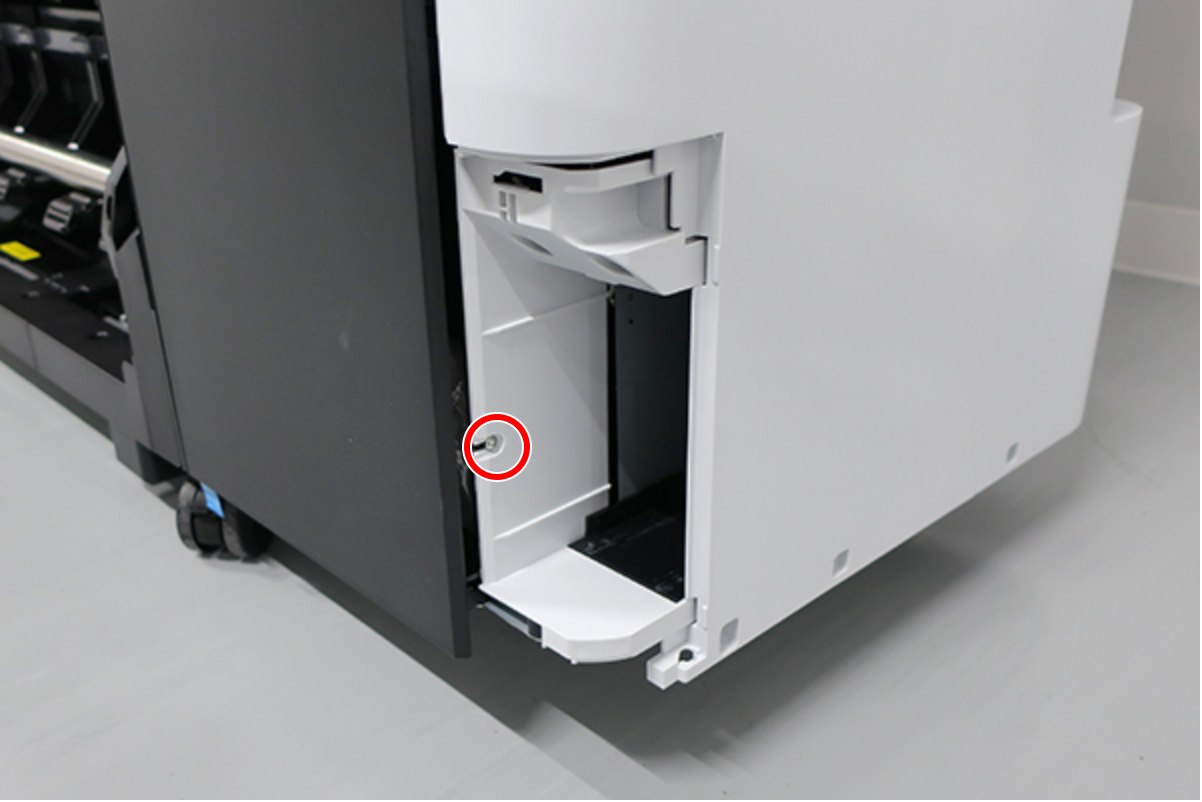
 : : Silver M3x8 Cup S-tite screw
- Insert a flathead screwdriver and release the 2 hooks each, and remove the two screw cover (A).
- Insert a flathead screwdriver and release the 2 hooks, and remove the screw cover (A).
- Remove the three screws at the front side.
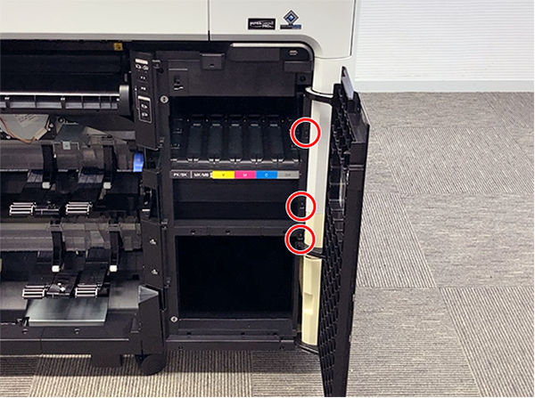
- : Black M3x8 Cup P-tite screw
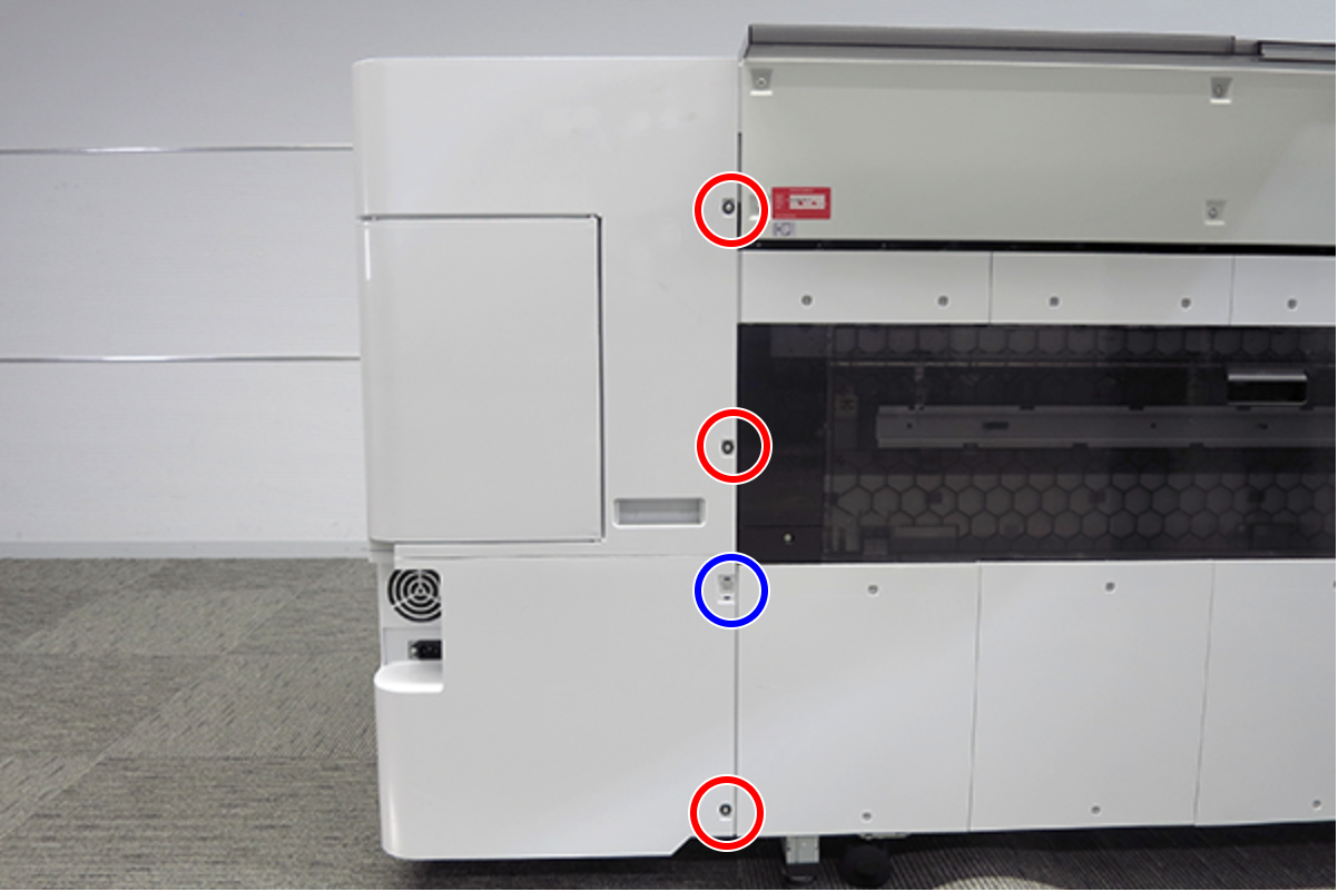
- Remove the five screws at the right side.
- : Silver M3x8 Cup S-tite screw
 : Silver/M4x8/machine screw
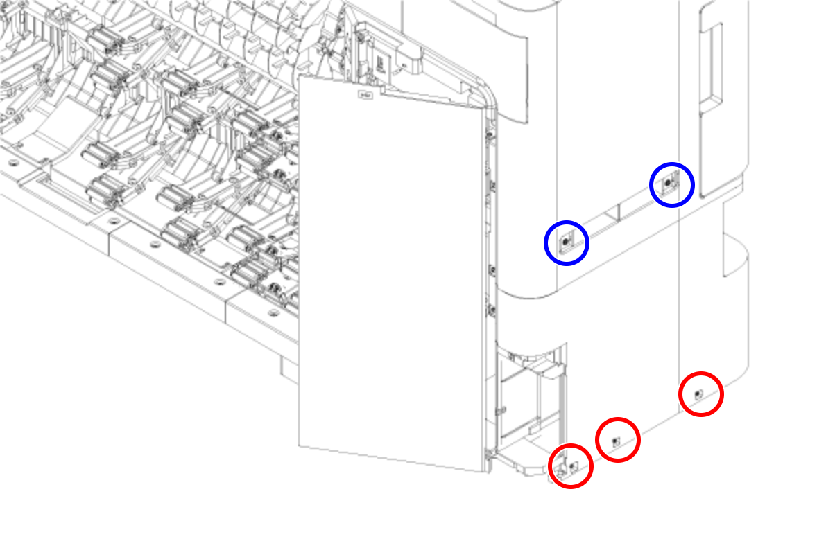
- Remove the four screws at the rear side.
- : Silver M3x8 Cup S-tite screw with plastic washer
- : : Silver M3x8 Cup S-tite screw
- On the printer rear side, release the dowel of the Home Side Cover Unit (A).
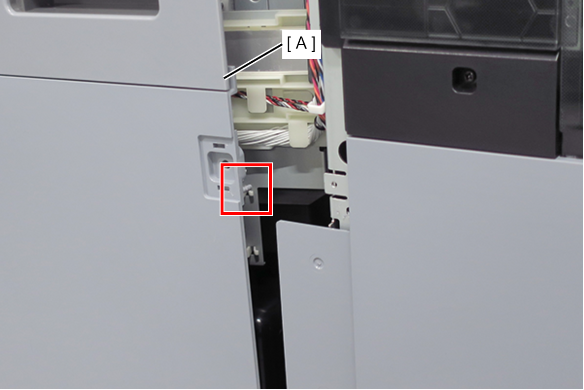
- Insert a flathead screwdriver and release the 2 tabs each, and remove the Home Side Cover Unit (A) in the direction of the arrow.
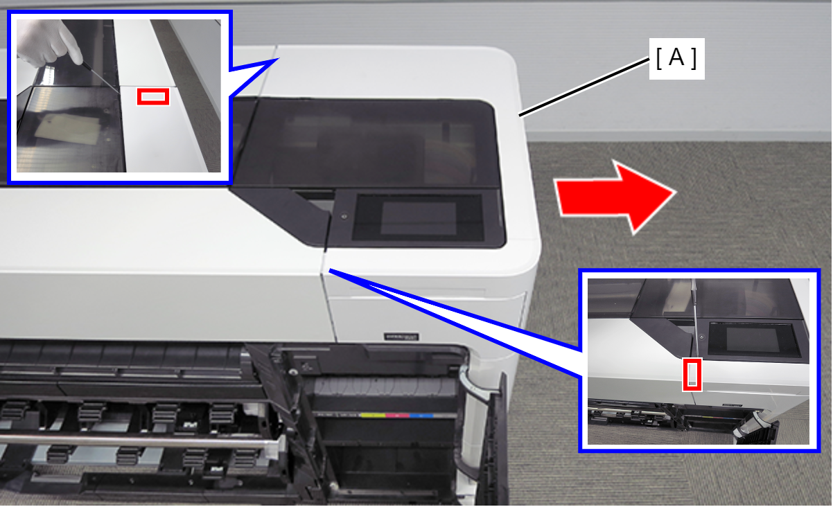
- Open the Printer Cover.
Remove the Home Side Top Cover (A).
 Assemble / 組み立て
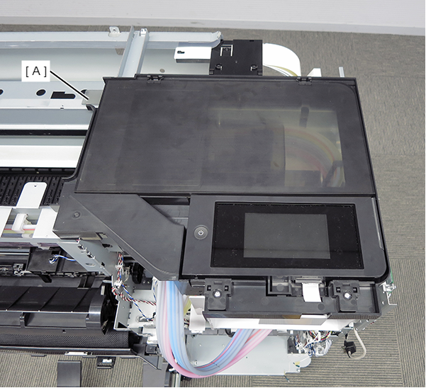
Set the two hinges of the Home Side Top Cover (A) on the guides of the Panel Lower Cover (B).
- Remove the four screws and then remove the Panel Hinge Cover (A).
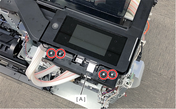
- : Silver M3x8 P-tite screw
 Lubrication / 注油
Before attaching the part, refer to the following and then lubricate.
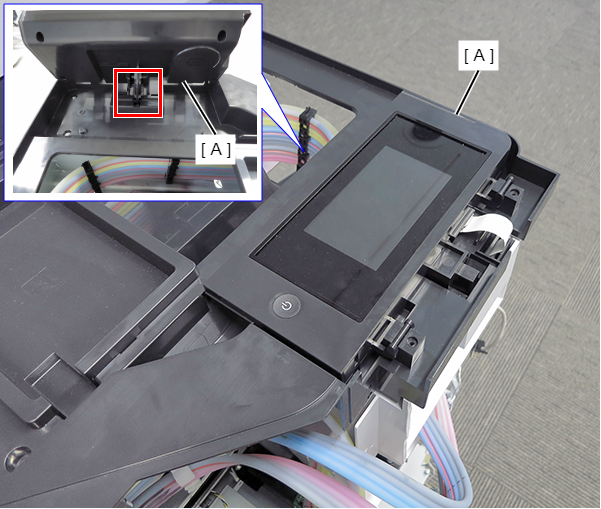
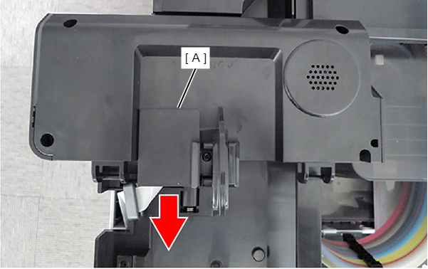
- Lift the Panel Assy (A), and release from the stopper.
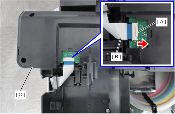
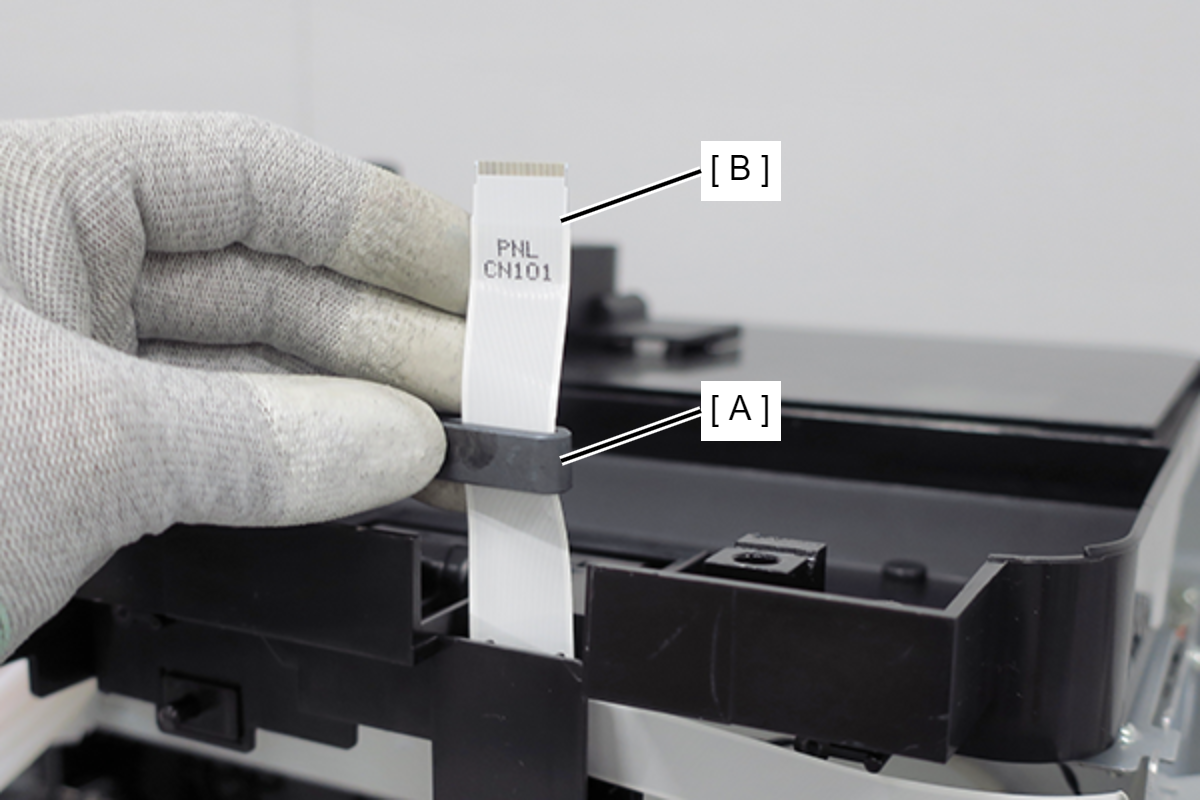
- Slide the FFC Cover (A) in the direction of the arrow to remove.
- With the connector metal part (A) pushed in the direction of the arrow, remove the FFC (B).
- Remove the Panel Assy (C).
- On the printer right side, remove the 11 screws (A).
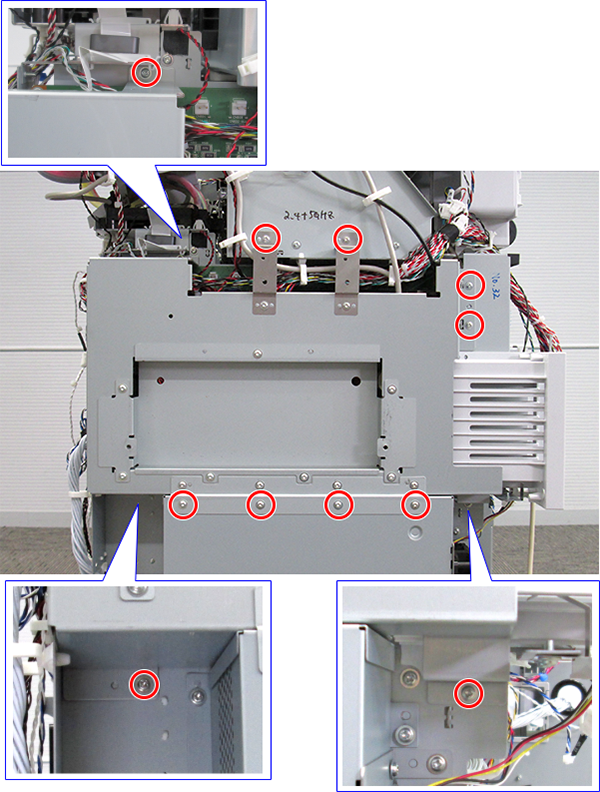
- : Silver M3x8 Cup S-tite screw
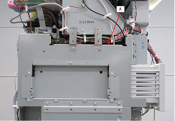
Remove the CH83 Main Circuit Board (A).
 Assemble / 組み立て
- Take care that the cables do not get pinched.
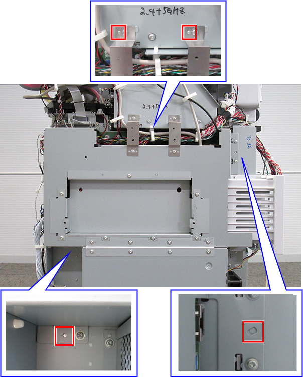
- There are four positioning locations.
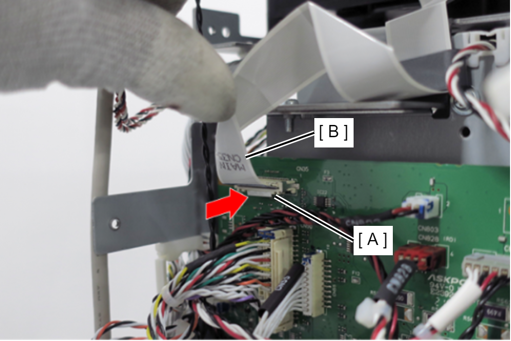
- Remove the ferrite core (A) from the Panel FFC (B).
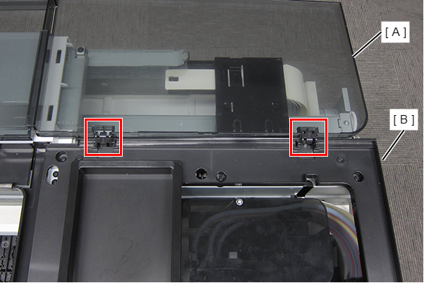
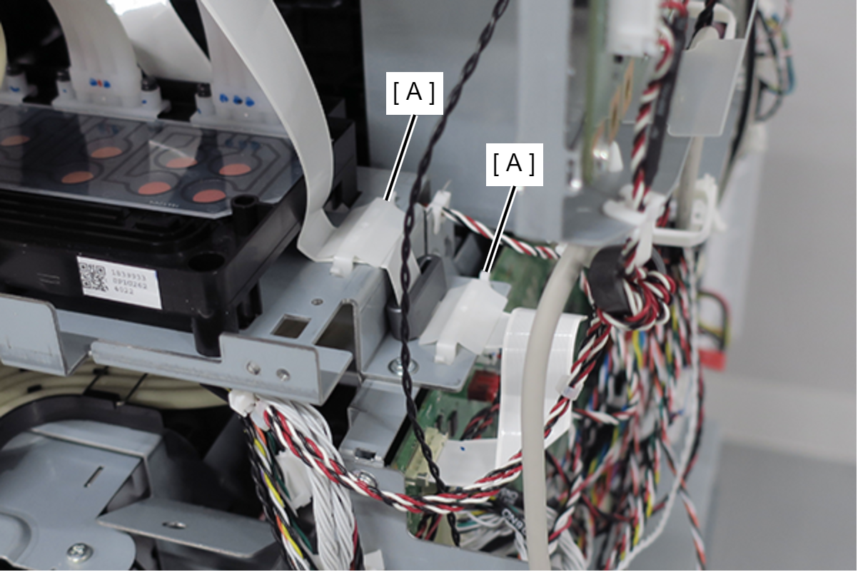
- Remove the two FFC clamps (A).
- Peel off the Panel FFC (B).
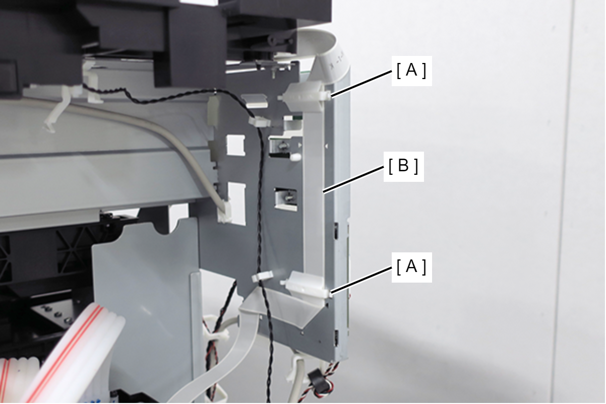
- Remove the two FFC clamps (A).
While pushing the connector locks (CN35) (A) in the direction of the arrow, remove the Panel FFC (B).
 Caution / 注意
The ferrite core is not included in the ASP Panel FFC Assy, so when installing the new part, ferrite core must be taken off the removed FFC and then installed.
 Adjustment / 調整 Adjustment / 調整 |
When removing/replacing this part, refer to following page and make sure to perform the specified operations including required adjustment. |