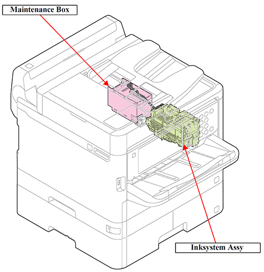
Ink System Mechanism
The inksystem mechanism of this product is composed of the Inksystem assy, and Maintenance Box.
The ink sucked by the Cap mechanism and Pump mechanism from the Printhead is drained via the Waste Ink Tube and into the Waste Ink Pad in the Maintenance Box.
The amount of waste ink is controlled by the counter in the firmware taking the amount of evaporation into account so as not to let the ink leak out of the printer because the waste ink exceeds the limit of the storage capacity.
Further, this product uses a mechanism by which the user him/herself can replace the Maintenance Box.
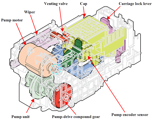
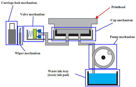
Operation Principle
The inksystem mechanism of this product employs the direct acting type* and consists of the carriage lock mechanism, wiper mechanism, capping mechanism, pump mechanism, and venting valve (valve mechanism).
All the mechanisms are driven by the pump motor.
The drive force of the pump motor is transmitted to each mechanism via transmission parts, such as the pump-drive compound gear, clutch gear, intermittent gear, cam, and drive lever.
Additionally, this product utilize a maintenance box (including a waste ink pad) that retains waste ink from the cap, allowing users to remove the waste ink by themselves. (By replacing the maintenance box.)
*: There are two types of the capping: direct acting type and sliding type. In the direct acting type, the cap moves up and down independently of the carriage and caps the printhead. In the sliding type, the printhead is capped (the cap is moved up) when the carriage pushes the cap slider.
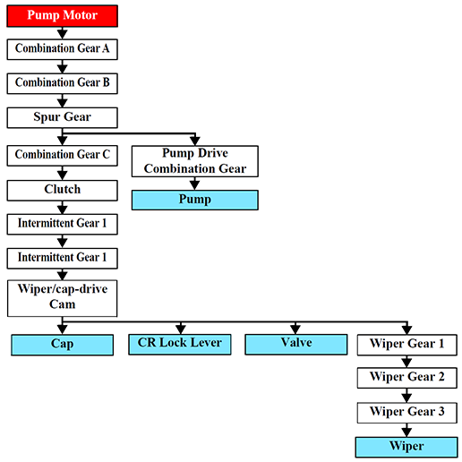
Drive Path
The ink system mechanism is driven by the Pump Motor.
The relationship between the Pump Motor rotational direction and operation of each part is as follows.
| Mechanism | Rotational direction of the Pump Motor * | |
|---|---|---|
| CW | CCW | |
Wiper | Wiping position | Passing |
| Cap | Drop | Rise (capping) |
| Pump | Release | Suction |
| CR lock | Drop (CR Lock release) | Rise (CR Lock set) |
| Venting valve | Open | Open |
*: Rotational direction seen from output shaft
Driving path is as follow.
| Symbol | Name | Symbol | Name |
|---|---|---|---|
| A | Combination Gear A | G | Intermittent Gear 1 |
| B | Combination Gear B (with Pump Encoder Scale) | H | Intermittent Gear (2) |
| C | Spur Gear | I | Wiper/cap-drive Cam |
| D | Pump Drive Combination Gear | J | Wiper Gear 1 |
| E | Combination Gear C | K | Wiper Gear 2 |
| F | Clutch | L | Wiper Gear 3 |
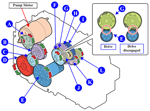
The Clutch, Intermittent Gear 1, Intermittent Gear 2, and Wiper/cap-drive Cam move linked to the rotation of Combination Gear C, but if the Wiper moves to the wiping position, the Intermittent Gear 2 teeth surface separate, and the Combination Gear C drive is disengaged.
At these times, the Wiper, Cap, Valve, and CR Lock Lever will not operate even if the Pump Motor is rotating.
If the Pump Motor rotates in the opposite direction, then the Intermittent Gear 2 and Combination Gear C will again mesh, operating each part.
This prevents mechanisms except the pump mechanism from driving while the Pump Motor rotates continuously to drive the pump mechanism.
Operation of Each Mechanism
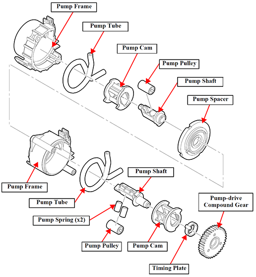
Pump Mechanism
The pump mechanism sucks ink from the printhead at cleaning.
The drive force from the Pump-drive Compound Gear is transmitted to the pump shaft via the Timing Plate.
This Timing Plate allows the Pump-drive Compound Gear to start rotating at the different timing from the Pump Shaft. After the PF Motor rotates for a while, the Pump Unit starts its operation.
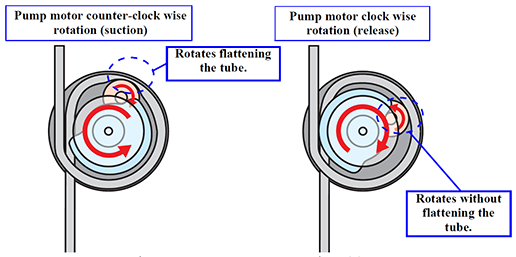
When the Pump Motor rotates counter-clock wise as seen from the output-shaft side of the motor, the drive force via the Pump-drive Compound Gear rotates the Pump Pulley to flatten the tube to suck the air (to generate negative pressure) inside the tube.
When the Pump Motor rotates clock wise, the Pump Pulley does not flatten the tube, and the negative pressure is released.
Furthermore, this products incorporate two pumps, with improved suction performance.
Cap mechanism
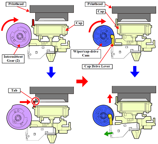
The direct acting type is employed in the capping mechanism, where the Cap is moved up and down by the Pump Motor and the printhead is capped at the suction for cleaning.
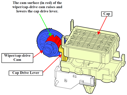
Intermittent Gear 2 rotates on drive power from the Pump Motor, and the cam surface on the Intermittent Gear 2 pushes the Cap, moving it forward.
At this time, the cap tab contacts the printhead surface, guiding the Printhead on the Cap.
Next, the Wiper/cap-drive Cam moves the Cap Drive Lever, raising the Cap, capping the Printhead.
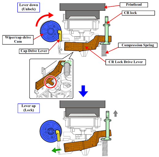
CR Lock Mechanism
The tension of the compression spring at the bottom of the CR Lock moves up the CR Lock.
When the CR Lock Drive Lever pushes the CR Lock downward, the CR Lock is released.
Since the CR Lock Drive Lever moves up and down together with the Cap Drive Lever, the CR Lock also operates together with the movement of the Cap.
This means that the printhead nozzle surface is always capped when the CR Lock is set.
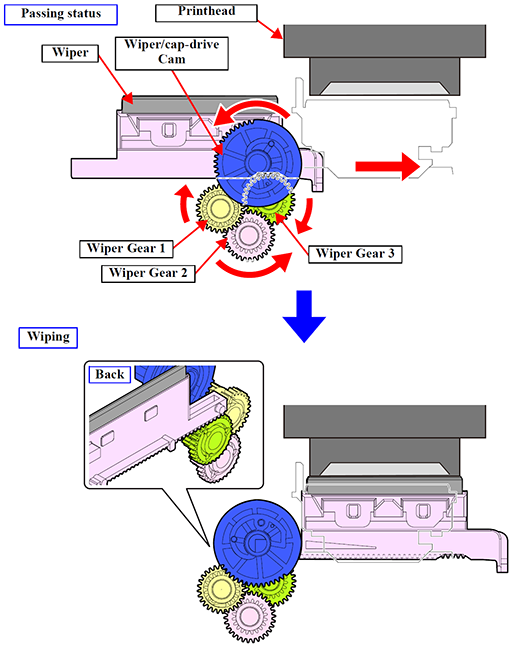
Wiper Mechanism
The rotation of the Wiper/cap-drive Cam drives the wiper mechanism.
After release, if the Wiper Cam rotates, the drive is conveyed to Wiper Gears 1, 2, and 3, and the Wiper moves along the CR unit path.
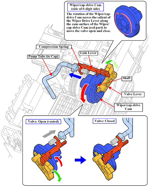
Venting valve
Before capping, the Valve Lever interferes with the Link Lever, therefore the Venting Valve opens.
During the capping sequence, the Valve Lever shaft moves along the Wiper/cap-drive Cam Slot, and the Valve Lever drops backwards.
When this happens, the Valve Lever and Link Lever interference is removed, and the return force of the Compression Spring makes this slide to the 80-digit side, closing the Venting Valve.