CR Motor (WF-M5899 Series)
 Adjustment / 調整 Adjustment / 調整 |
When replacing/removing this part, refer to the following pages and make sure to perform the specified operations including the required adjustments. |
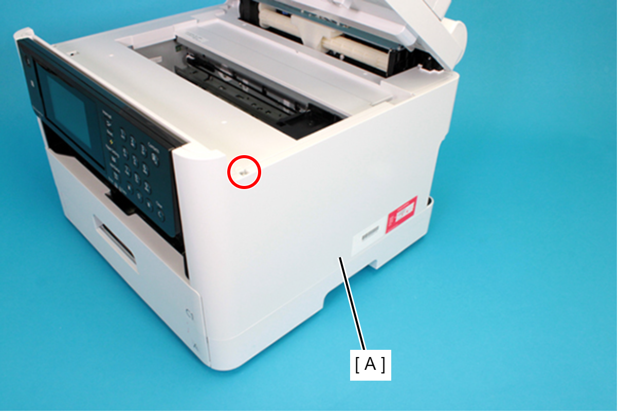
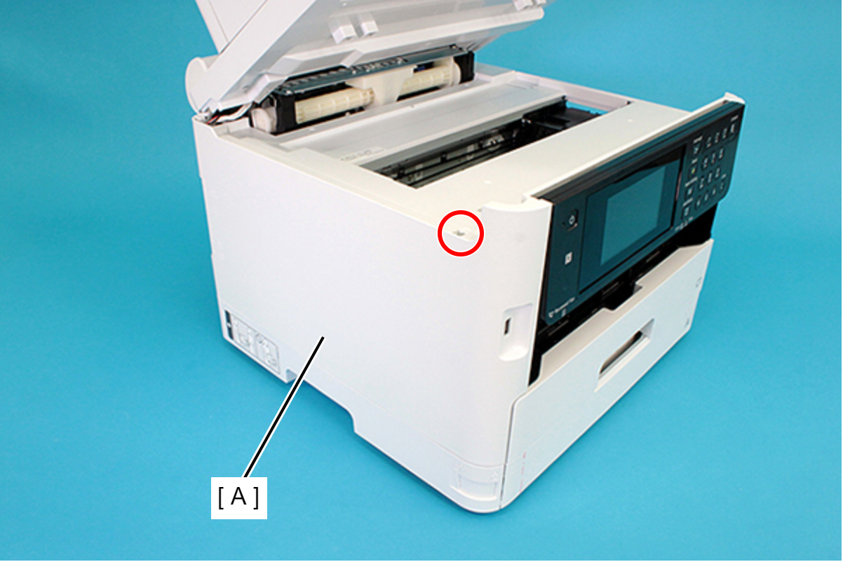
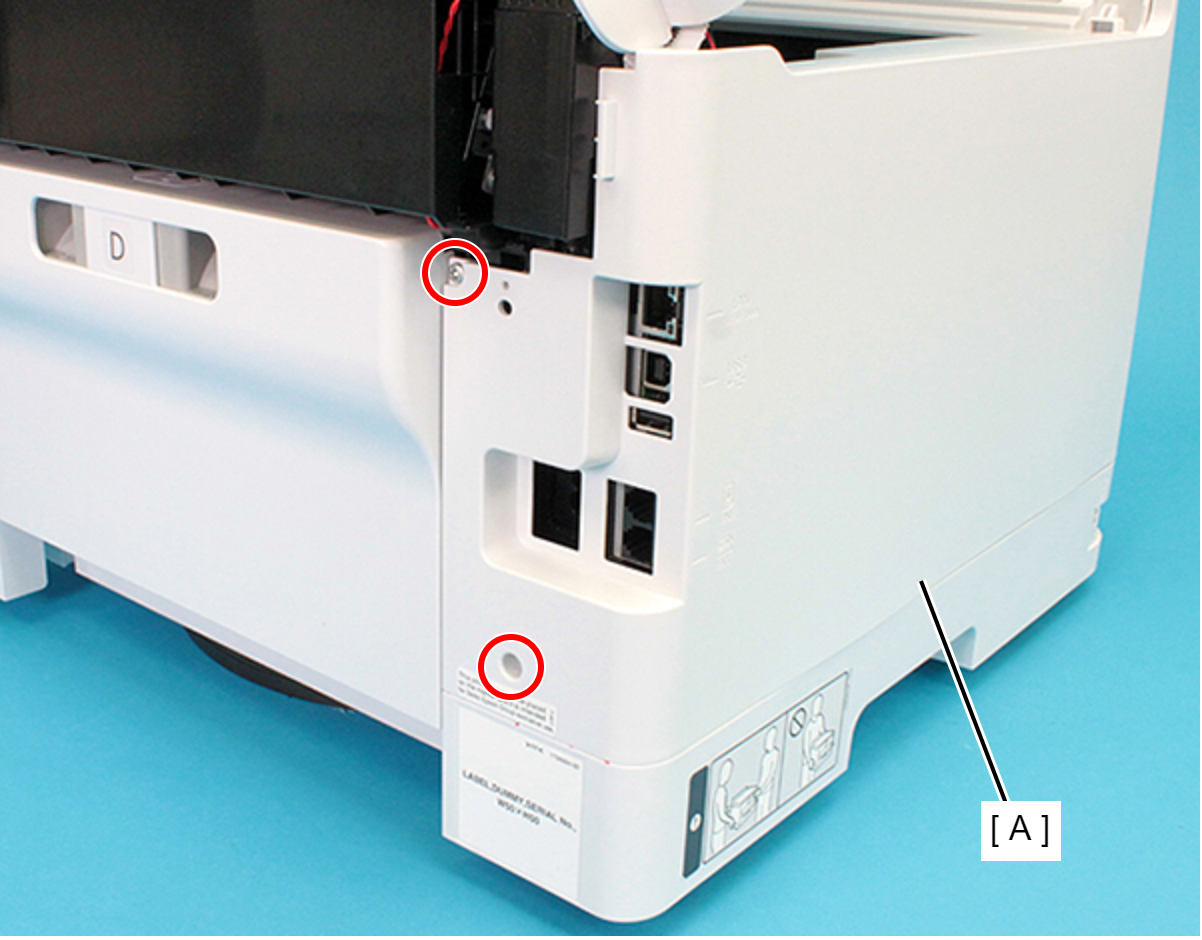
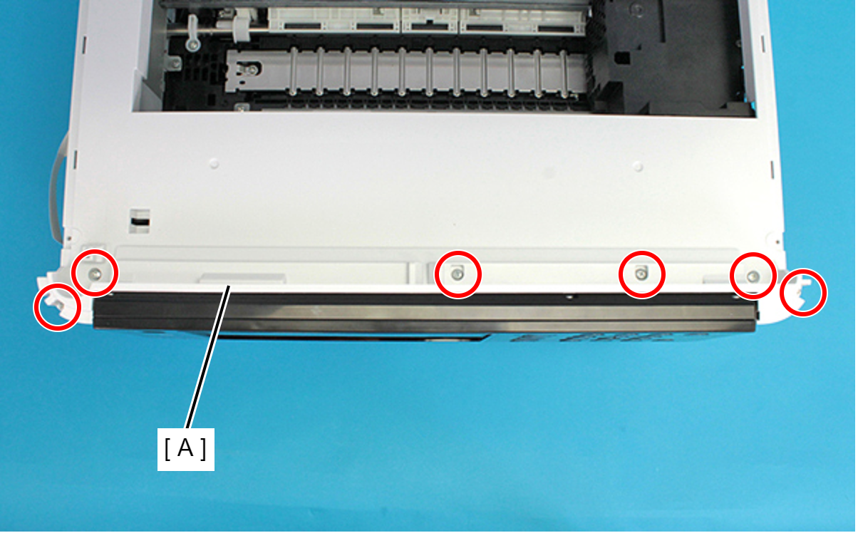
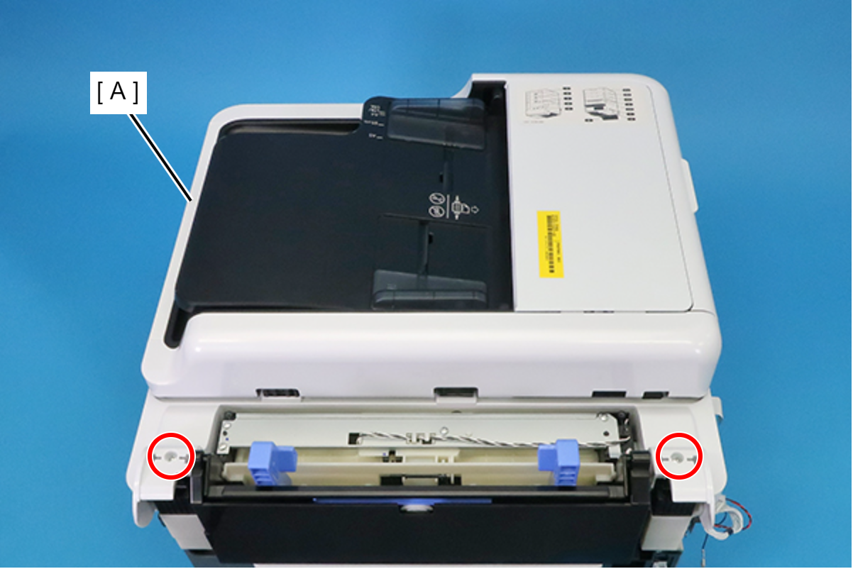
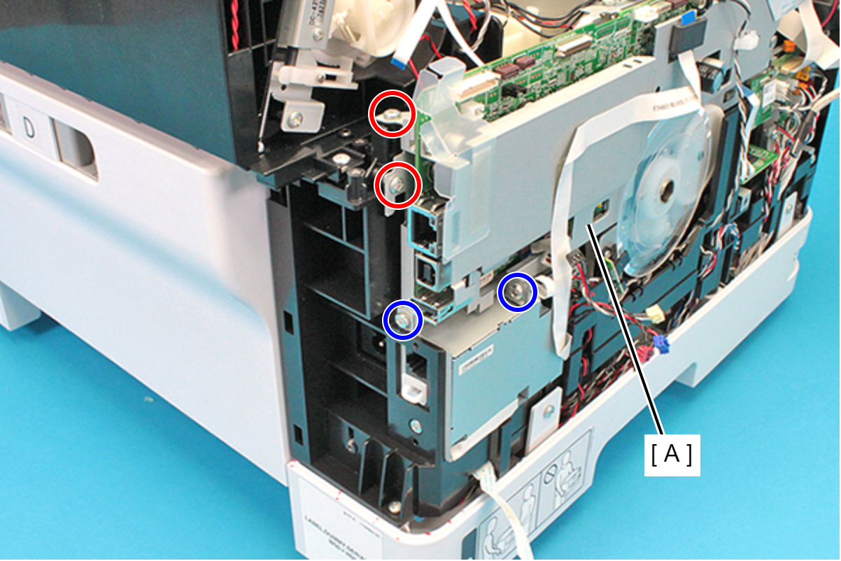
- Remove the four screws and then remove the Rear Housing Assy (A).
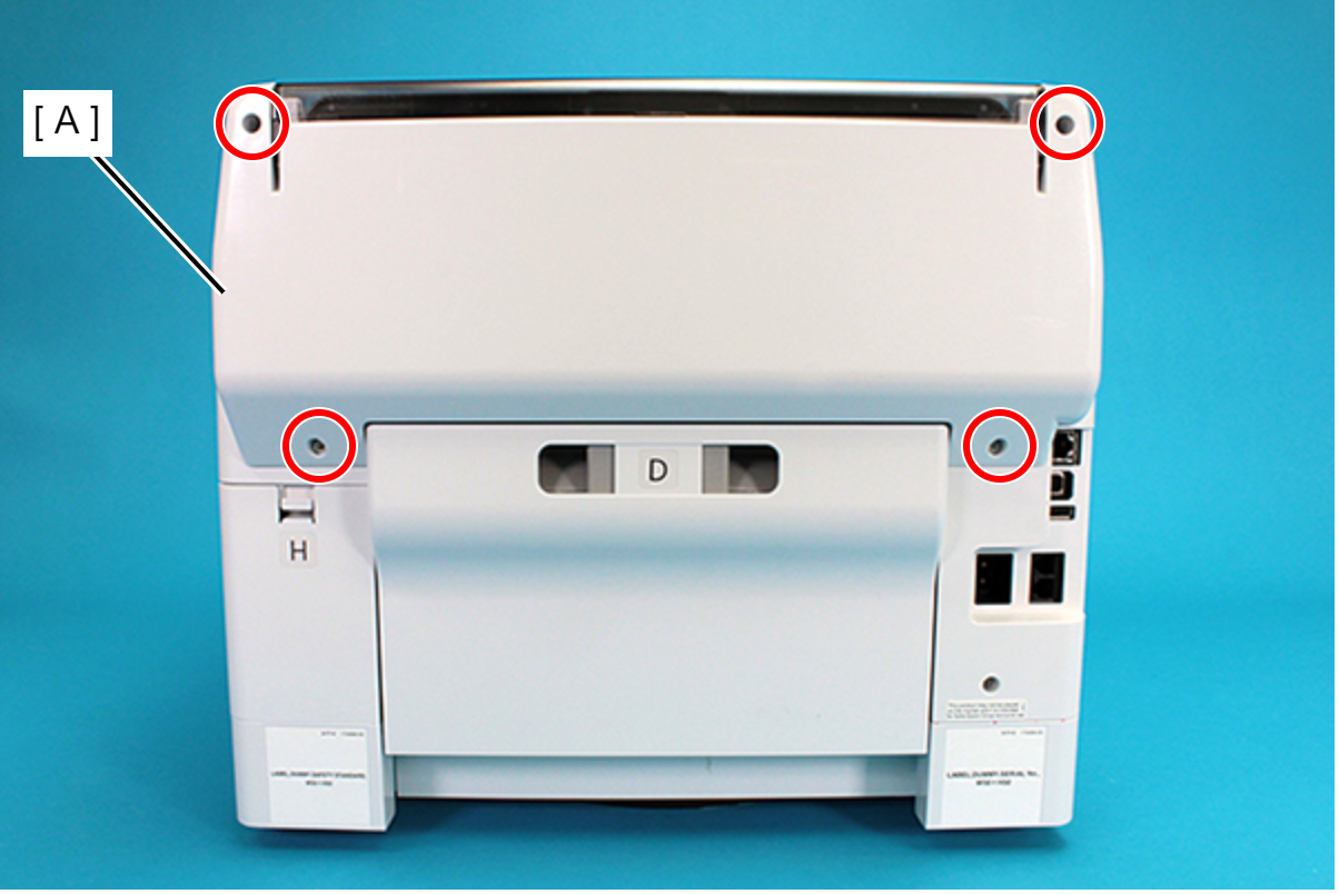
 : C.B.P-TITE-SCREW-3x10-F.ZN-3C
 Assembly / 組み立て
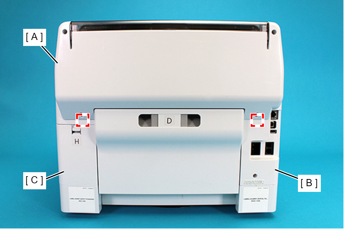
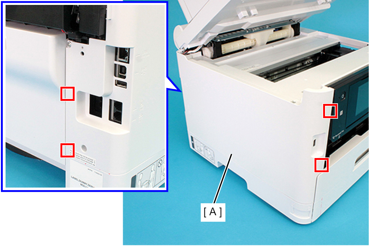
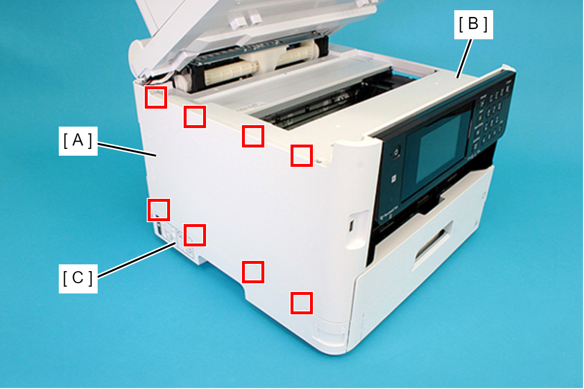
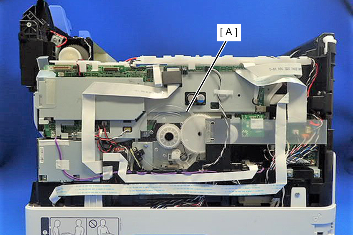
Attach the two dowels of the Rear Housing Assy (A) to the positioning holes on the Housing Left (B) and the Housing Right (C).
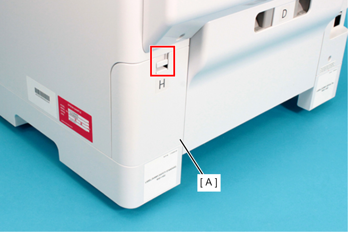
- Disengage the hook, and remove the Maintenance Box Cover (A).
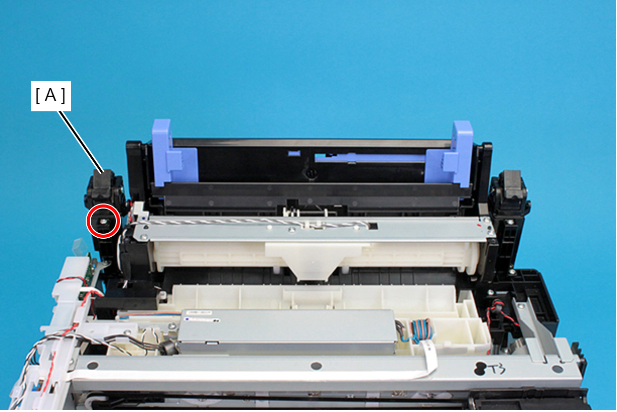
- Open the ADF/SCN Unit and remove the screw securing the Housing Right (A).
- : C.B.P-TITE-SCREW-3x10-F.ZN-3C
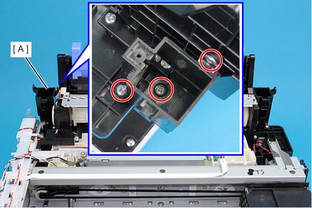
- Remove the three screws securing the Housing Right (A).
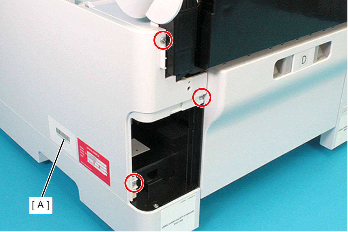
- : C.B.P-TITE-SCREW-3x10-F.ZN-3C
- Lift the Housing Right (A) upward to release the two hooks on the front side of the Housing Right (A).
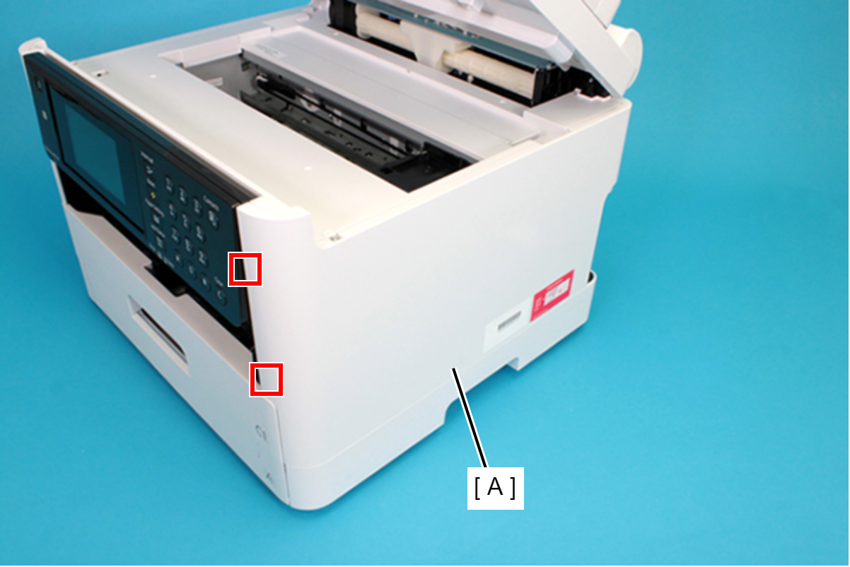
Remove the dowels to the rear, and lift up the Housing Right (A) to remove it.
 Assembly / 組み立て
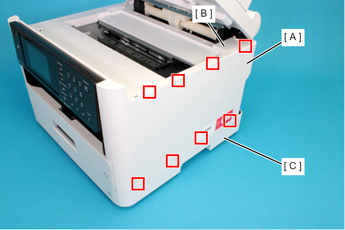
Insert the eight tabs on the Housing Right (A) to the positioning holes of the Housing Upper (B) and the RIPS Unit (C).
- Open the ADF/SCN Unit and remove the screw securing the Housing Left (A).
- : C.B.P-TITE-SCREW-3x10-F.ZN-3C
- Remove the two screws securing the Housing Left (A).
- : C.B.P-TITE-SCREW-3x10-F.ZN-3C
Lift the Housing Left (A) upward to release the two hooks each on the front side and rear side of the Housing Left (A), and then remove the Housing Left (A).
 Assembly / 組み立て
Insert the eight tabs on the Housing Left (A) to the positioning holes of the Housing Upper (B) and the RIPS Unit (C).
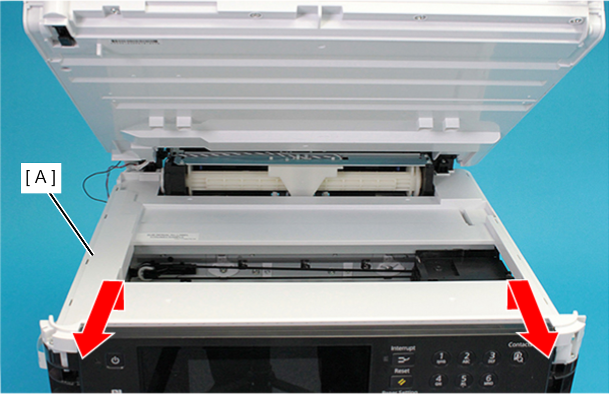
- Remove the six screws securing the Housing Upper (A).
- : C.B.P-TITE-SCREW-3x10-F.ZN-3C
- Lift the Housing Upper (A) and remove the Housing Upper (A) toward you.
- Remove the two screws, then remove the ASF Front Cover (A) upward.
- : C.B.P-TITE-SCREW-3x10-F.ZN-3C
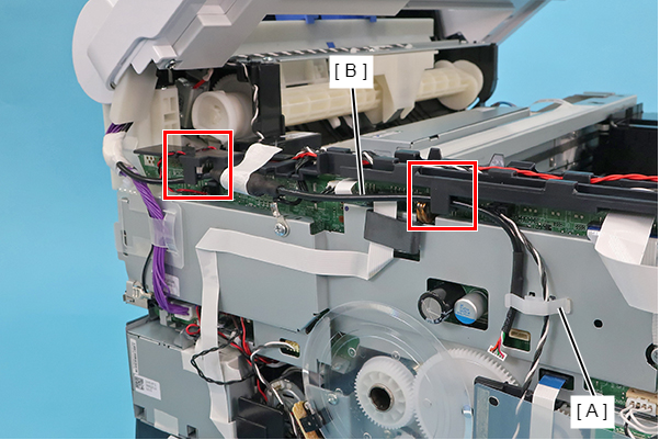
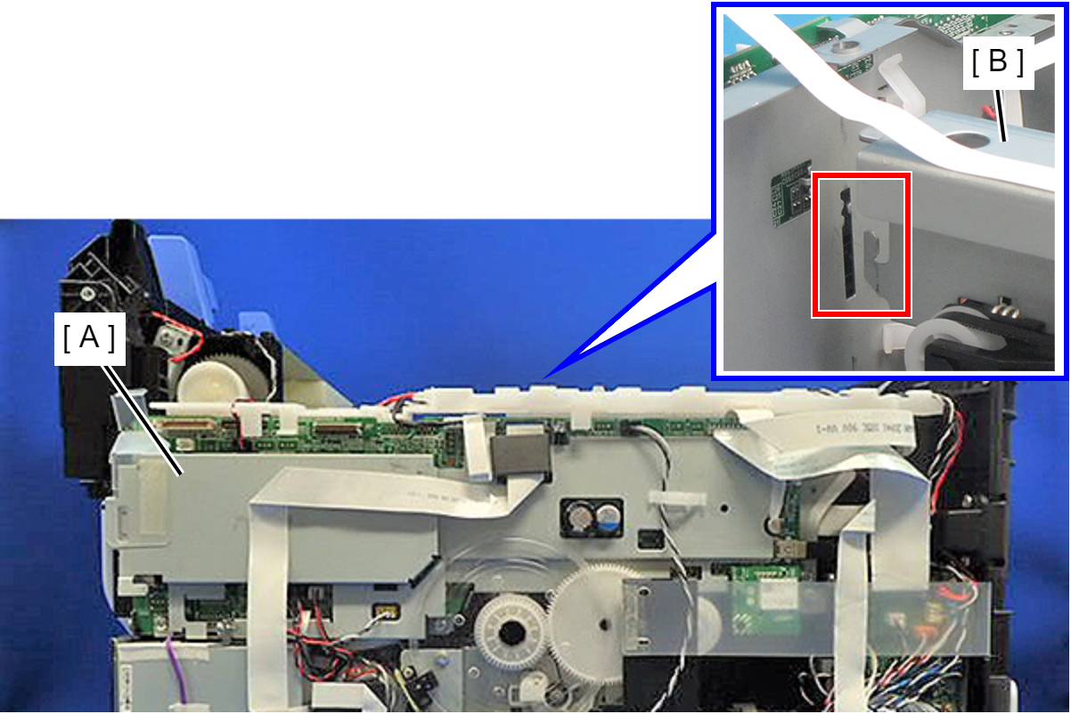
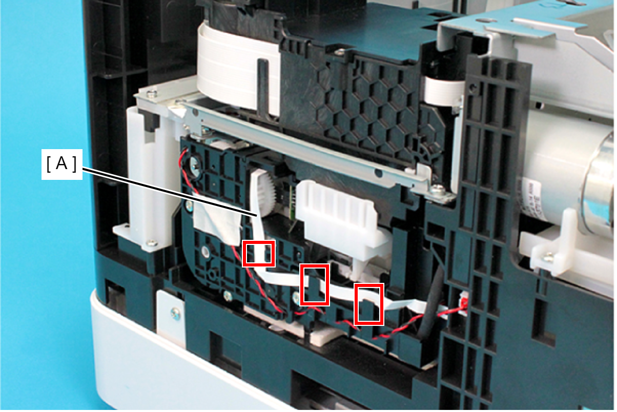
Remove the two pieces of acetate tape (A), and disconnect the cable (C) from CN100 connector on the Main Board (B).
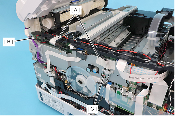
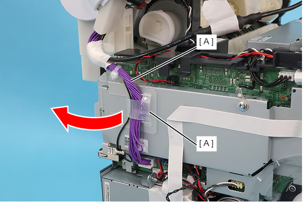
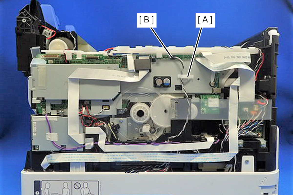
Release the cable (B) from the two guides and the clamp (A).
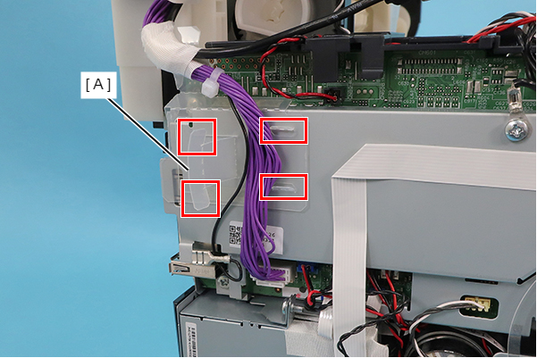
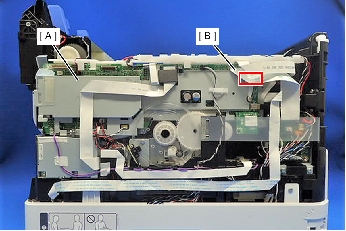
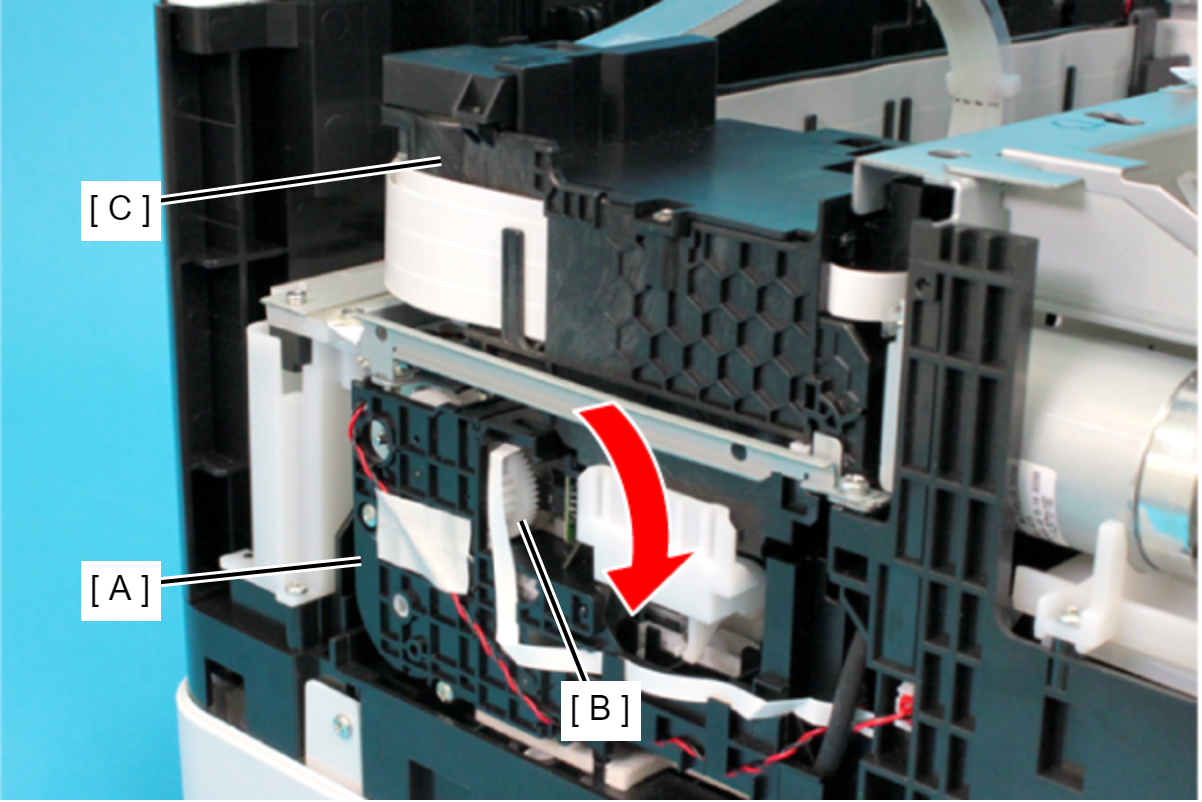
Release the cable (B) from the protective sheet (A) by opening the sheet in the direction of the arrow.
 Assembly / 組み立て
Insert the two tabs of the protective sheet (A) into the two slits respectively.
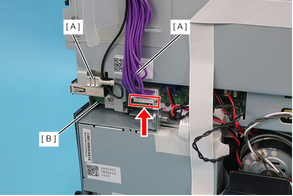
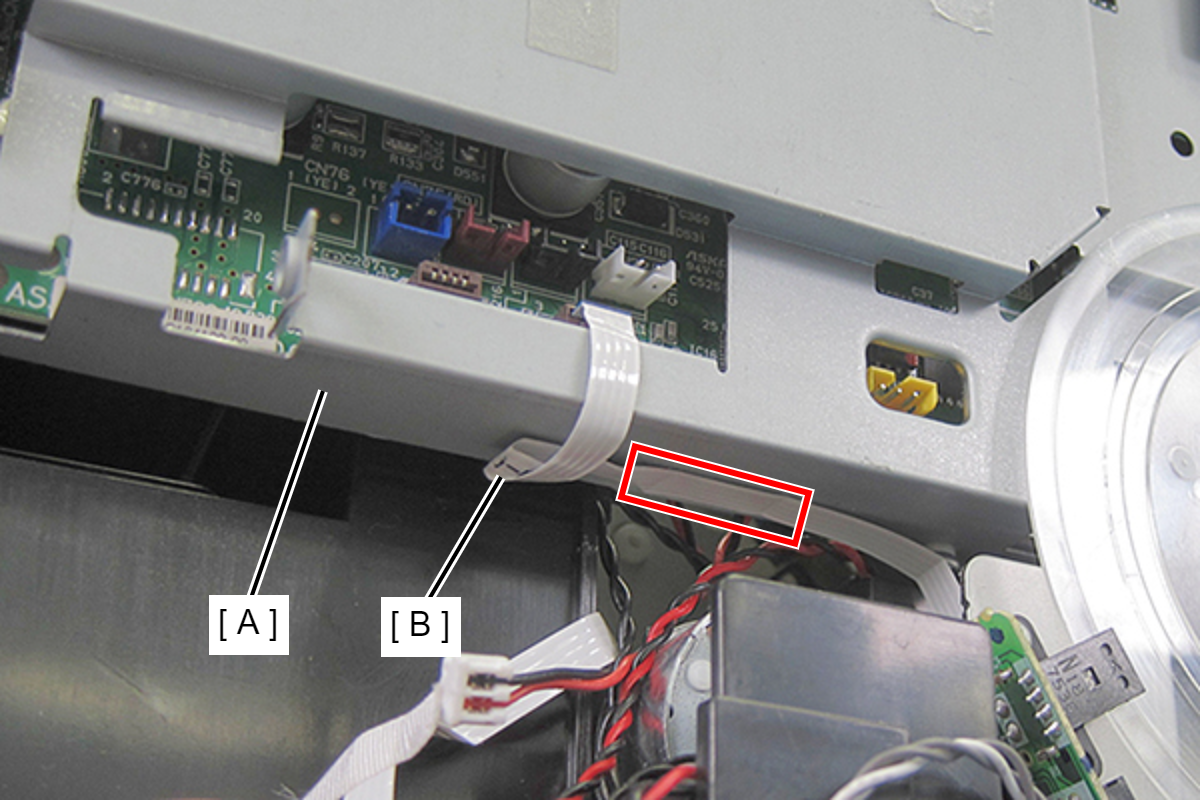
Disconnect the ground wire (A), and while pushing the connector’s tab upward, disconnect the cable (C) from CN799 connector on the Main Board (B).
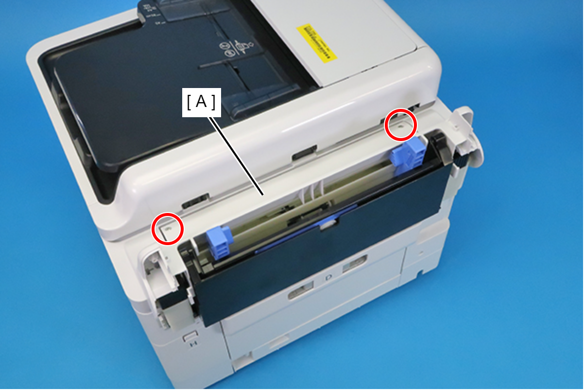
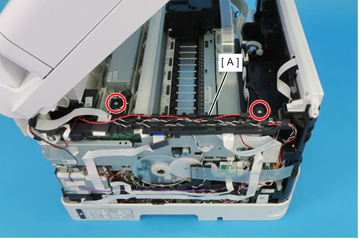
- Close the ADF/SCN Unit (A) and remove the two screws, and remove the ADF/SCN Unit (A) upwards.
- : C.B.P-TITE-SCREW-3x10-F.ZN-3C
Assembly / 組み立て- Before screwing the ADF/SCN Unit, make sure the hinges are properly attached in place.
If the ADF/SCN Unit is opened when the hinges are NOT secured, the unit may be damaged.
- Remove the screw and then remove the Hinge Assy (Left) (A).
- : C.B.P-TITE-SCREW-3x10-F.ZN-3C
- Remove the three screws, and remove the Hinge Lower Cover (Left) (A).
- : C.B.P-TITE-SCREW-3x10-F.ZN-3C
- Remove the two screws securing the Cable Guide (A).
- : C.B.P-TITE-SCREW-3x10-F.ZN-3C
 Check Point / チェックポイント
When removing the screws, if the screwdriver interferes with the ADF/SCN Unit, use a stubby screwdriver.
- Peel off the CRCM FFC (B) from the CRCM FFC Sheet (A).
- Peel off the double-sided tape at two locations and then remove the CRCM FFC Sheet (A).
- Disconnect the cables (B) from the connector (CN20, CN51, CN56) of the Relay Board (A).
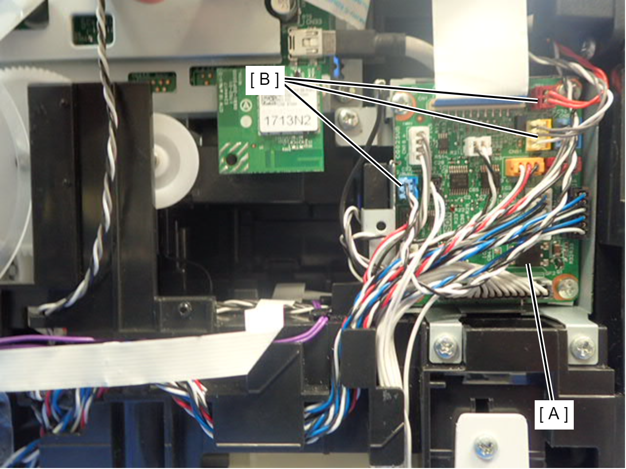
- Remove the acetate tape (A), and release the cable (B) from the two guides.
- Disconnect the two cables (B) from the connectors (CN74, CN80) of the Main Board (A).
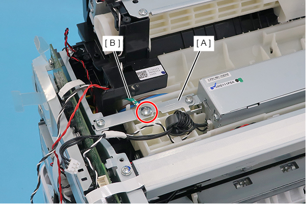
- Remove the two screws, and release the ground wire (A) from the slit to remove it.
- : C.B.S-TITE-SCREW-3x6-F.ZN-3C
Assembly / 組み立てAttach the ground wire with the terminal (A) oriented as shown below.
- Move the Cable Guide as shown below.
- Remove the two screws, then remove the PS Ground Plate (A).
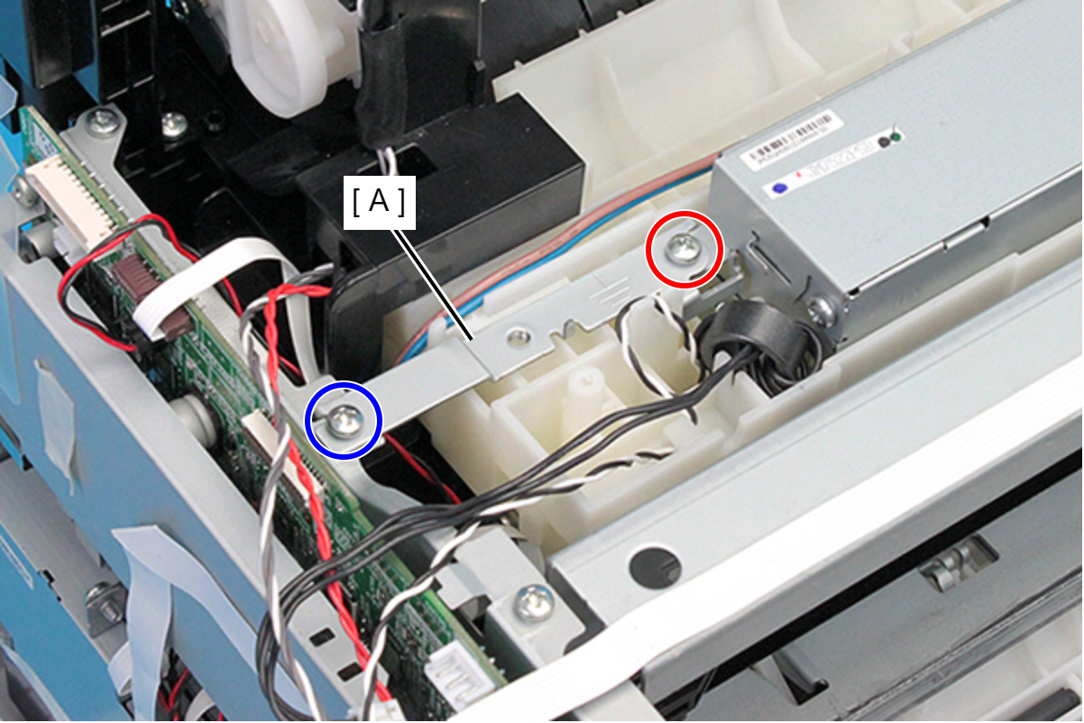
 : C.B.P-TITE-SCREW-3x10-F.ZN-3C
 : C.B.S-TITE-SCREW-3x6-F.ZN-3C
Check Point / チェックポイントA ground wire (B) is connected to the PS Ground Plate (A) depending on the region of sale.
If the ground wire (B) is connected, remove the wire (B) by removing the screw.
- : C.B.(O)SCREW,4X5,F/ZN-3C
Assembly / 組み立てAssemble ensuring that screw types are correct.
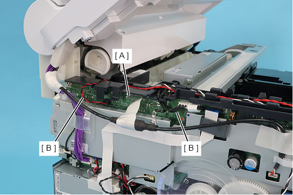
- Disconnect the FFCs (A) and cables (B) from the connectors (CN2, CN9, CN51, CN43, CN55, CN609) on the Main Board.
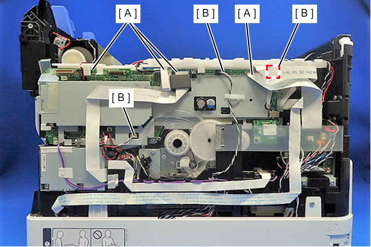
Disconnect the FFCs (A) and cable (B) from the connectors (CN3, CN67, CN66, CN68, CN41, CN8) on the Main Board.
 Check Point / チェックポイント
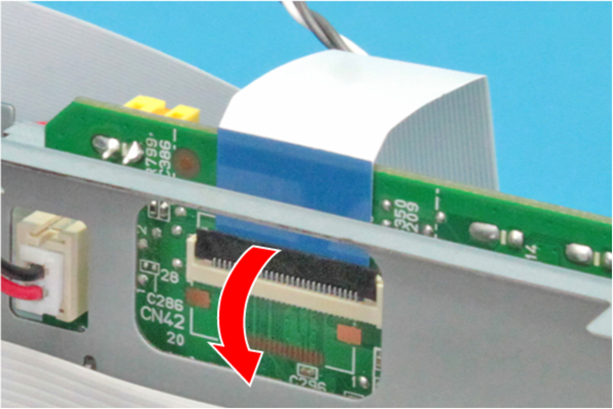
Release the connector (CN41) on the Main Board by lowering the connector lock in the direction of the arrow.
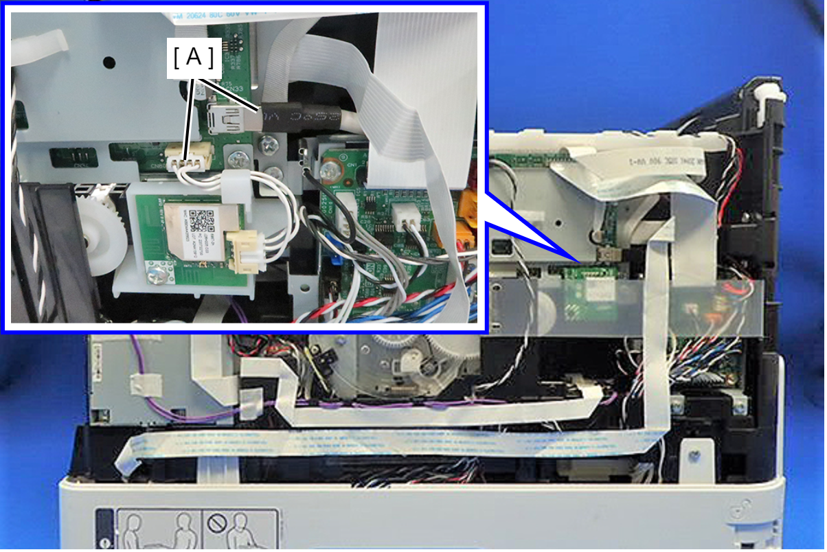
- Disconnect the cables (A) from the connector (CN33, CN802) on the Main Board.
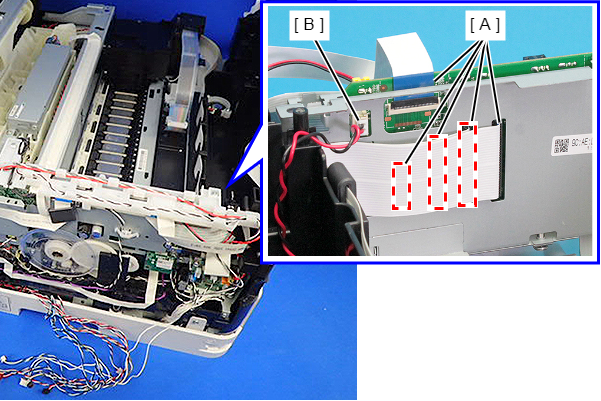
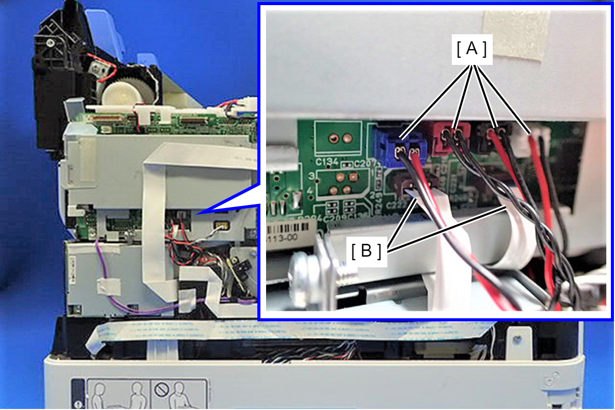
- Disconnect the FFCs (A) and cables (B) from the connectors (CN50, CN52, CN72, CN73, CN75, CN77) on the Main Board.
- Remove the two pieces of double-sided tape for the FAX FFC (B) from the MB Shield Plate Upper (A), and remove the ferrite core (C) from the FAX FFC (B).
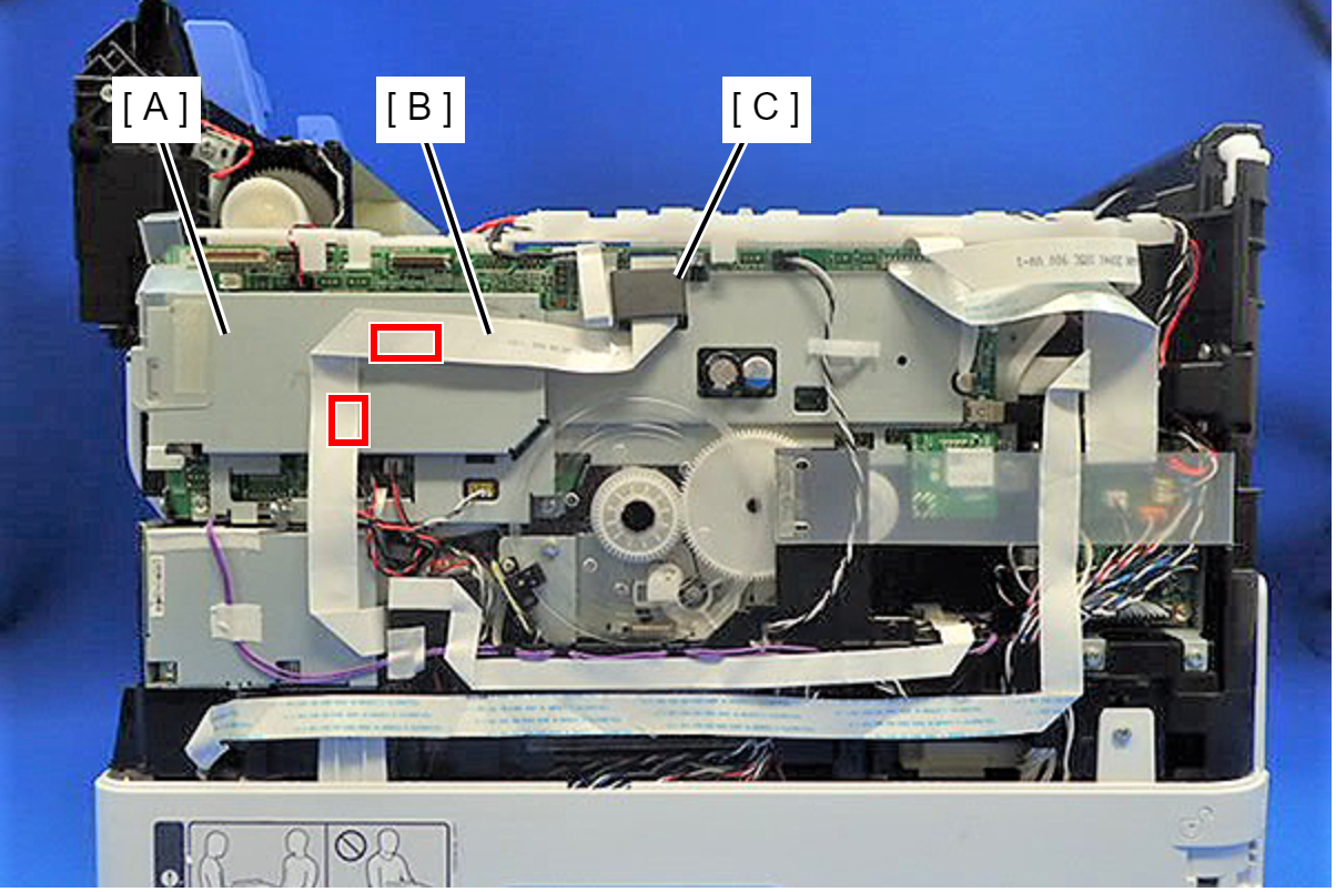
- Release the PE Sensor Cable (B) from the clamp (A).
- Peel off the double-sided tape of the Relay FFC (B) from the MB Shield Plate Upper (A).
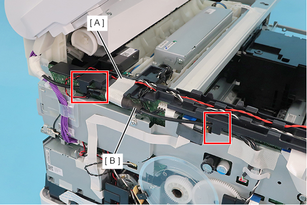
- Release the CR motor cable (B) from two clamps (A).
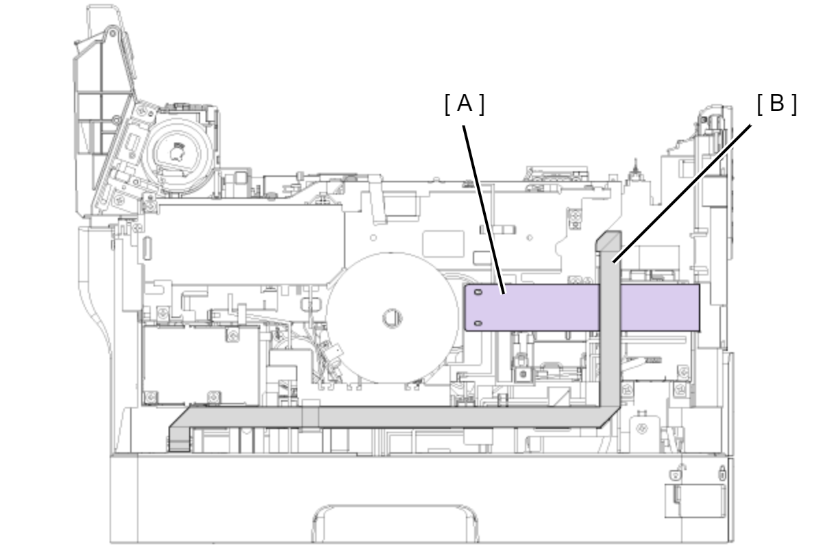
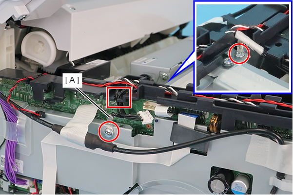
- Remove the five screws securing the Main Board Assy (A).
- : C.B.P-TITE-SCREW-3x10-F.ZN-3C
- : C.B.S-TITE.P4.SCREW-3X8-F.ZN-3
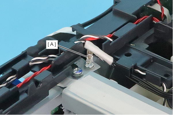
- Remove the screws securing the Main Board Assy (A).
- : C.B.P-TITE-SCREW-3x10-F.ZN-3C
- : C.B.S-TITE-SCREW-3x6-F.ZN-3C
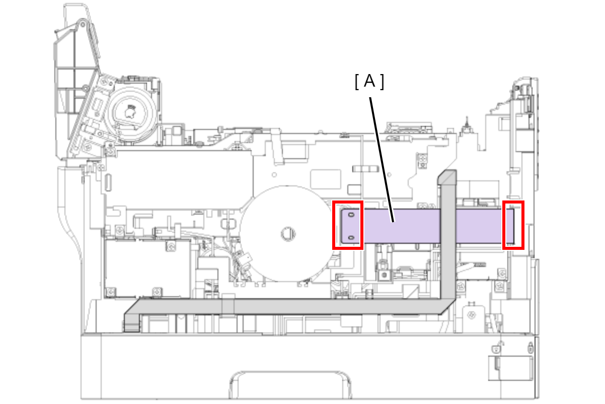
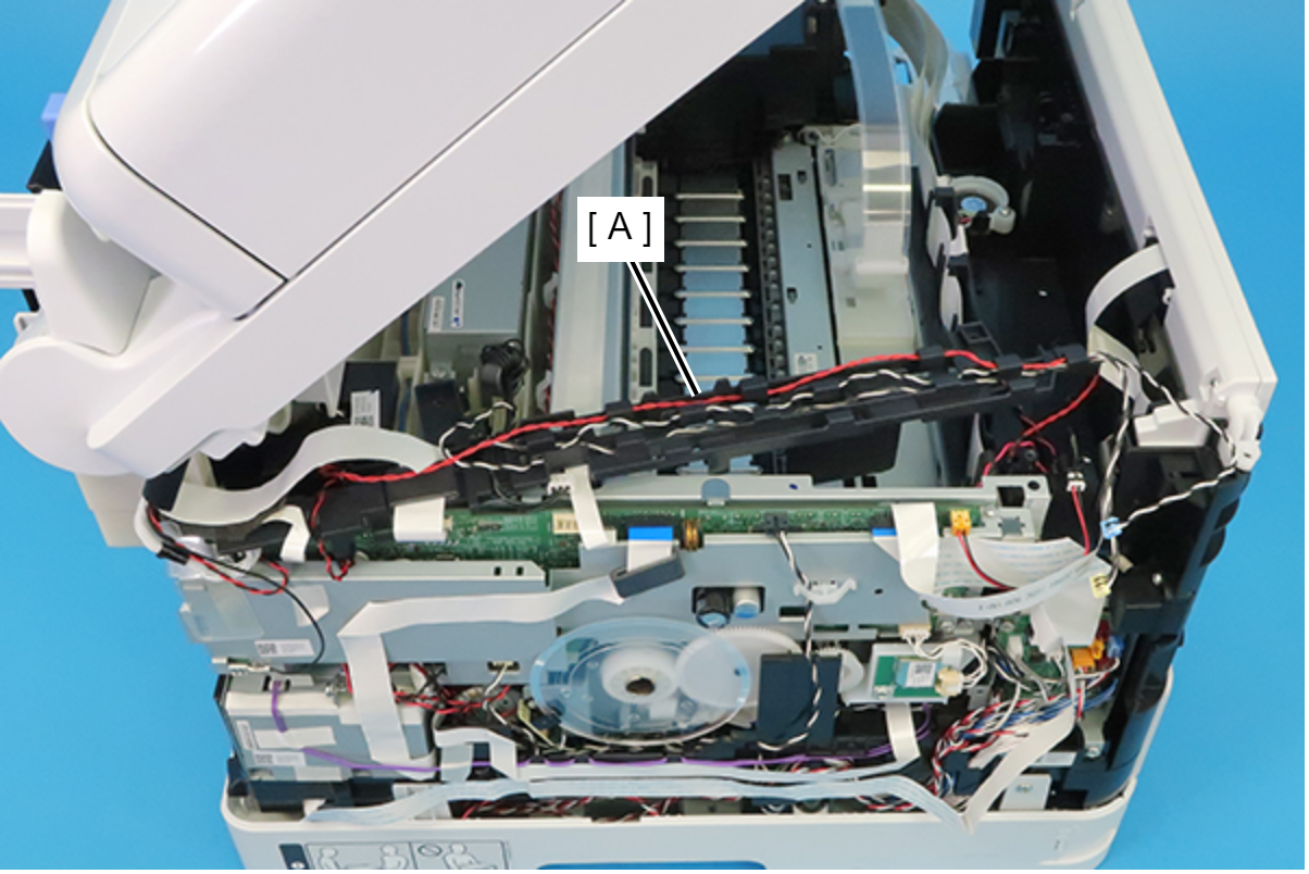
 Caution / 注意
In the next step, be careful not to damage the PF Scale.
Disengage the hole of the Main Board Assy from the hook of the CR Guide Frame, then remove the Main Board Assy upward.
 Assembly / 組み立て
Affix the FFC (B) to connect to the Main Board Assy (A) connector (CN52) using double-sided tape at the positions in the figure below.
- Release the FFC (A) from the three hooks.
Rotate the gear (B) of the Ink System Unit (A) in the direction of the arrow, and move the CR Unit (C) to the left side.
 Caution / 注意
When rotating the gear of the Ink System Unit, take extra care not to damage or disconnect the FFC by touching it.
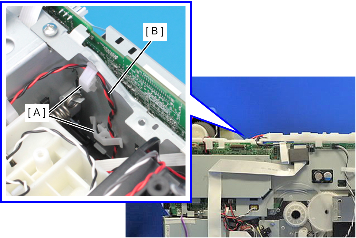
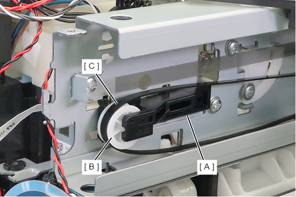
While holding the CR Driven Pulley Assy (A) by hand, remove the Extension Spring 27.7 (B) from the two hooks using long nose pliers.
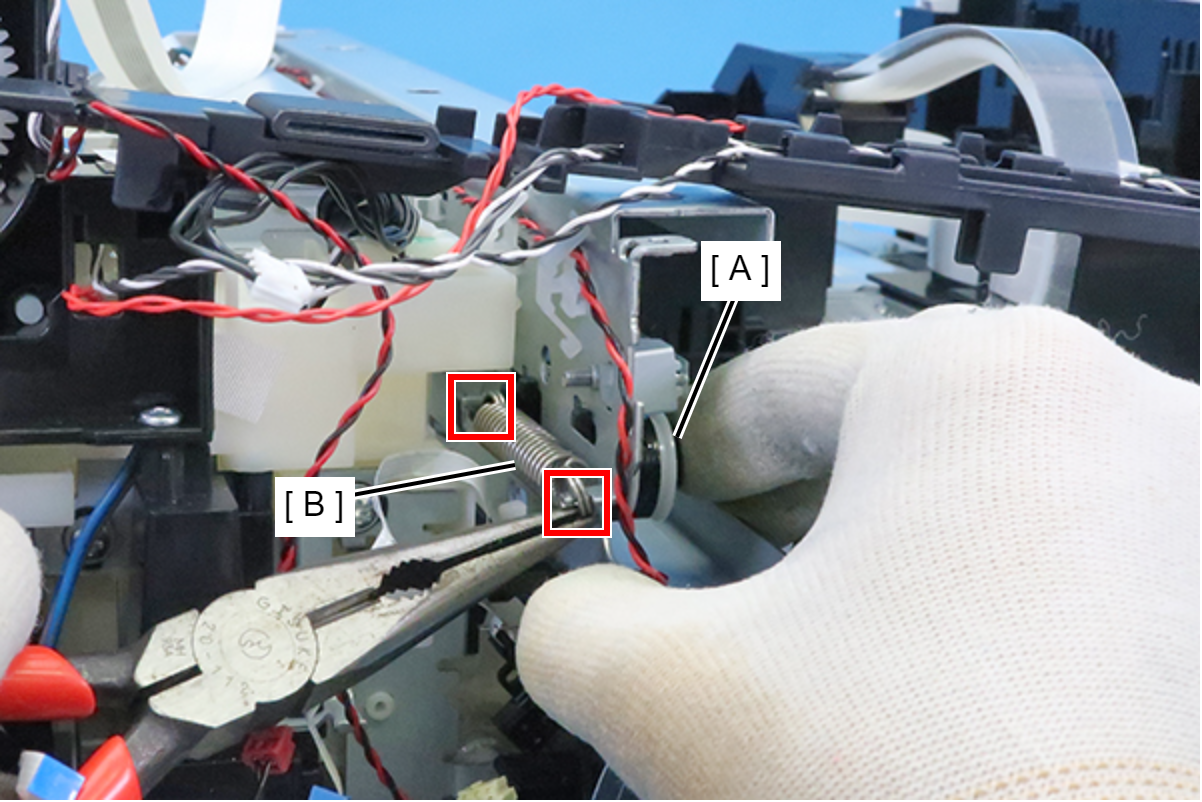 Caution / 注意
In order to prevent the Extension Spring 27.7 from flying out, be sure to remove the spring while holding it with long nose pliers. Otherwise, the spring may fly out resulting in damaging your eyes or etc.
Slide the CR Driven Pulley Assy (A) in the direction of the arrow to remove.
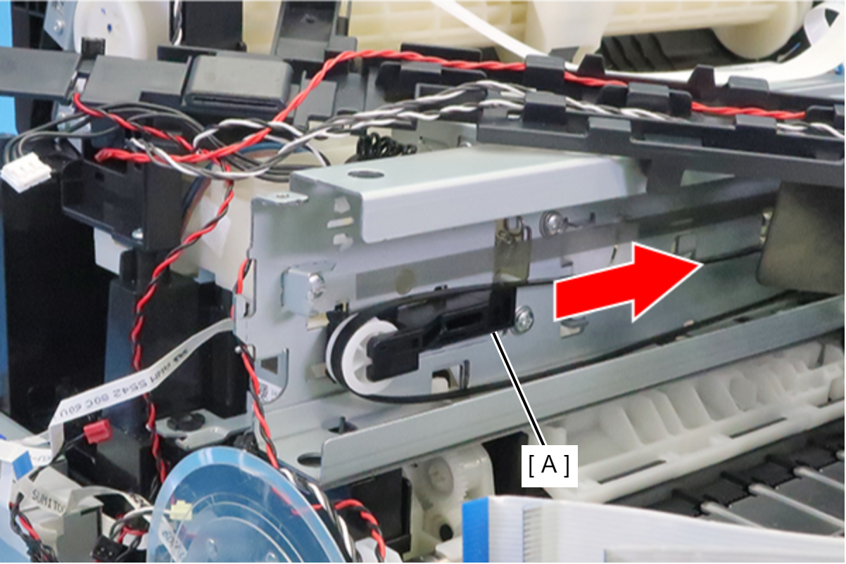 Assembly / 組み立て
- When installing the CR Driven Pulley Assy (A), insert its four protrusions into the four grooves in the frame.
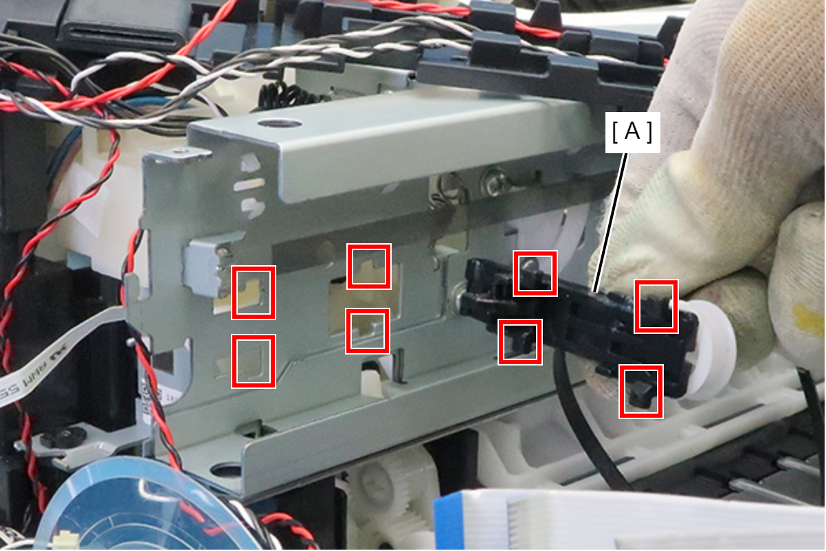
- After installing the CR Driven Pulley Assy (A), put the CR Timing Belt (C) on the pulley (B).
 Lubrication / 注油
Before installation, refer to the following and carry out lubrication.
- When installing the CR Driven Pulley Assy (A), insert its four protrusions into the four grooves in the frame.
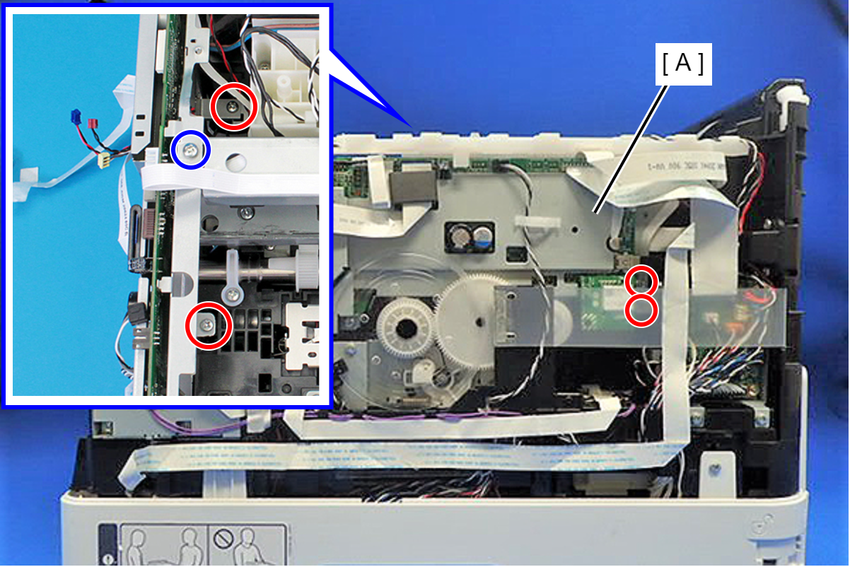
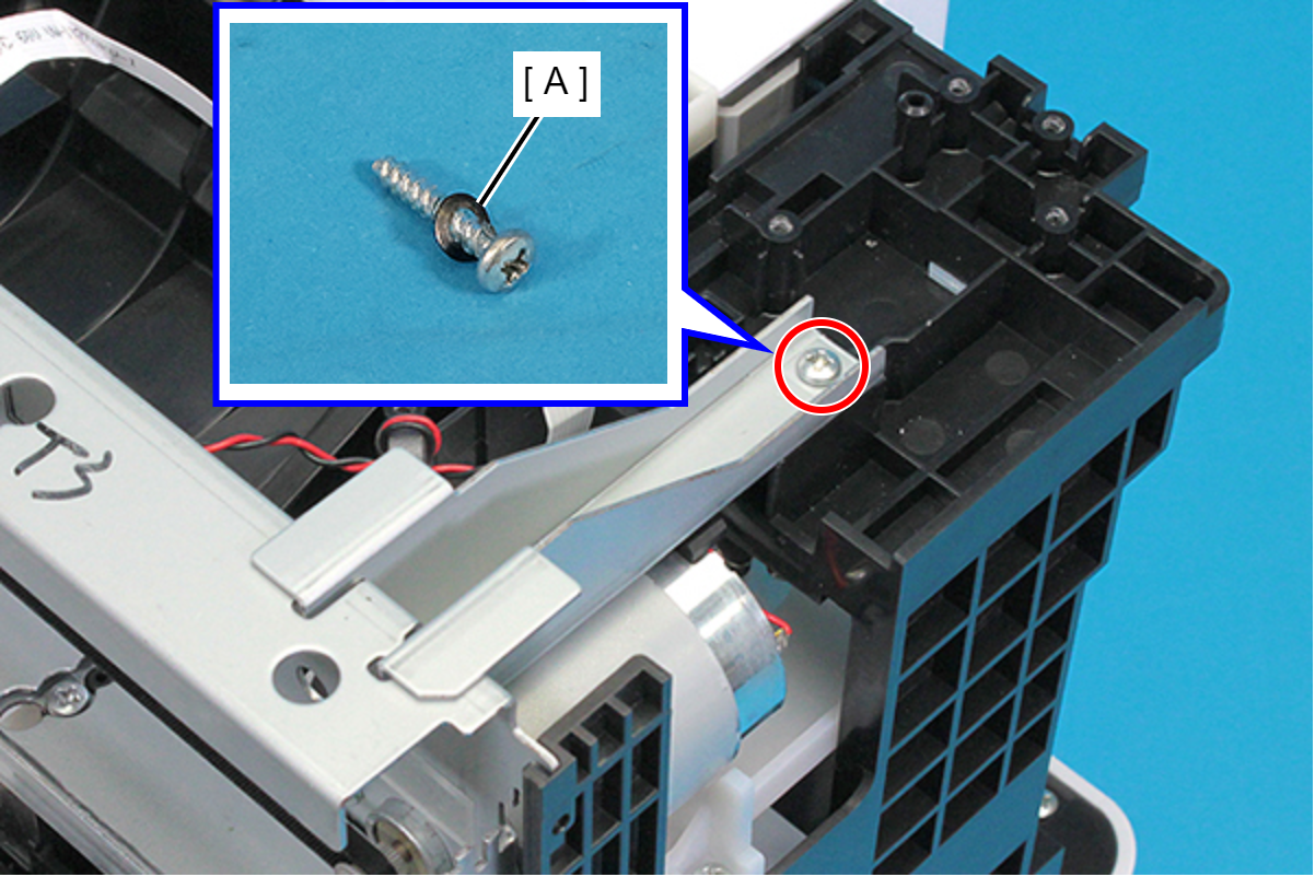
- Remove the screw and remove the Frame Plate (A).
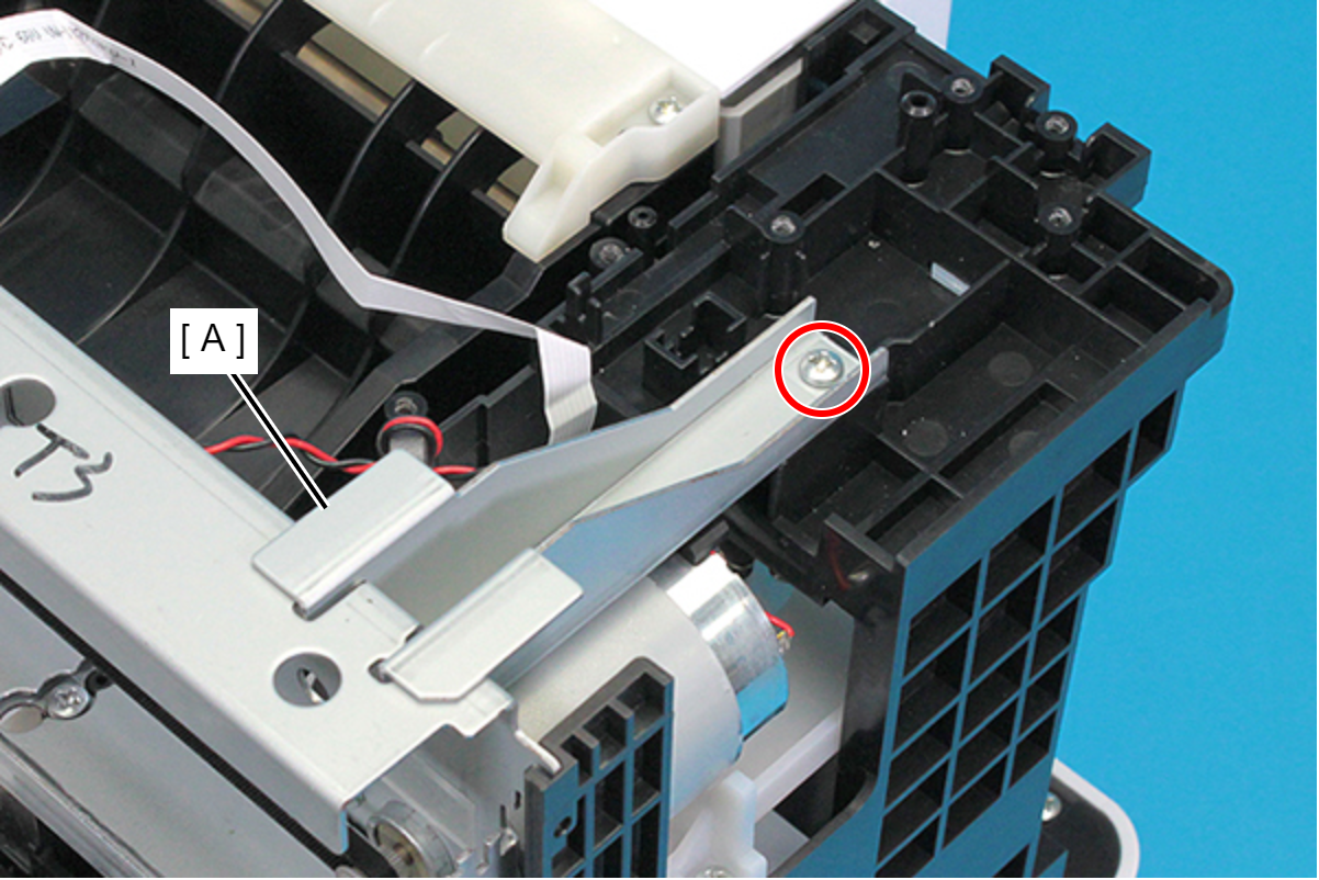
- : C.B.P-TITE-SCREW-3X16-FZN3C
Assembly / 組み立てThe washer (A) is attached with the screw shown below. Be sure to attach the washer (A) when tightening the screw.
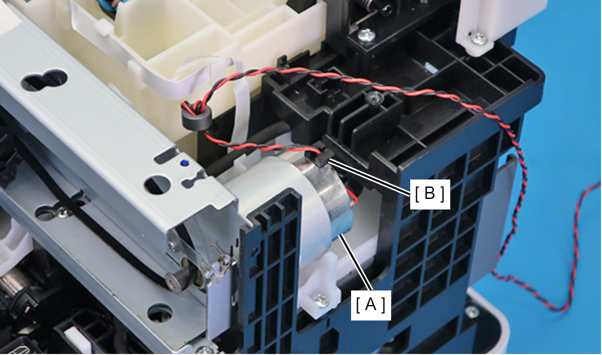
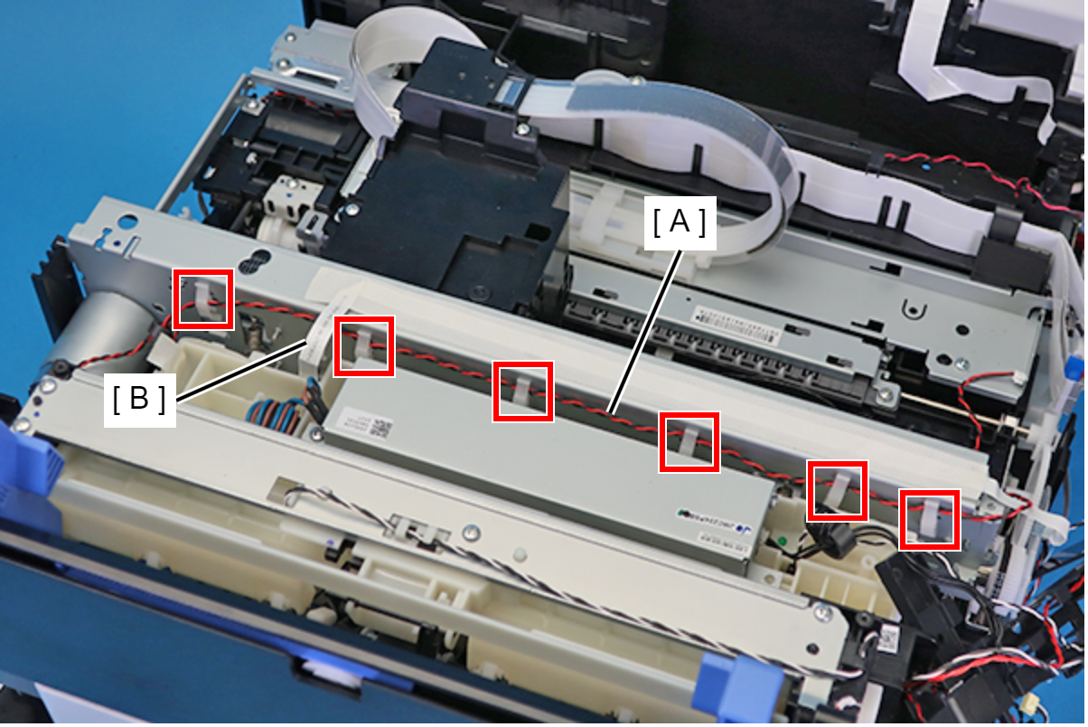
- Release the cable (A) from the six clamps and pull the cable (A) out while passing it under the CRCM FFC (B).
- Remove the two screws, then remove the CR Motor (B) from the Main Frame Assy (A).
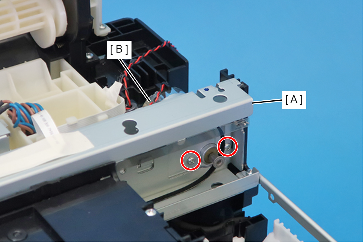
- : C.P.SCREW,3X4,F/ZN-3C
Assembly / 組み立てInstall the CR Motor (A) with its cable holder (B) facing upward.