Ink Supply Tube (WF-M5399 Series)
 Adjustment / 調整 Adjustment / 調整 |
When replacing/removing this part, refer to the following pages and make sure to perform the specified operations including the required adjustments. |
With the printer power ON, move the Lock Lever (A) in the direction of the arrow, and open the Ink Pack Cover (B).
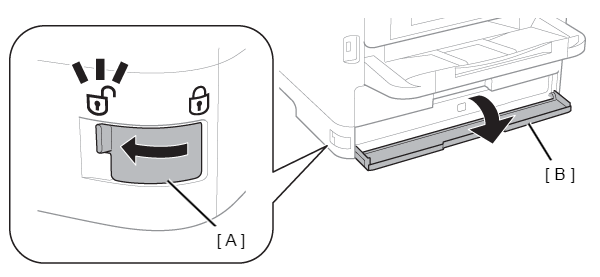
 Check Point / チェックポイント
- In the next step, when securing the lever of the Cover Open Sensor with tape, secure it properly ensuring there is no peeling of the tape during adjustment. (If the tape peels, the “Cover open error” will occur and the adjustment process will be interrupted.)
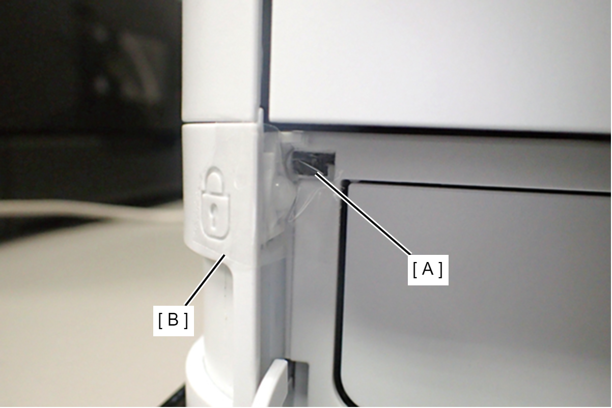
- If Steps 2 and 3 are reversed, then sensor control within the printer will generate an “Ink cartridge not installed error”, and starting ink discharge work will not be possible.
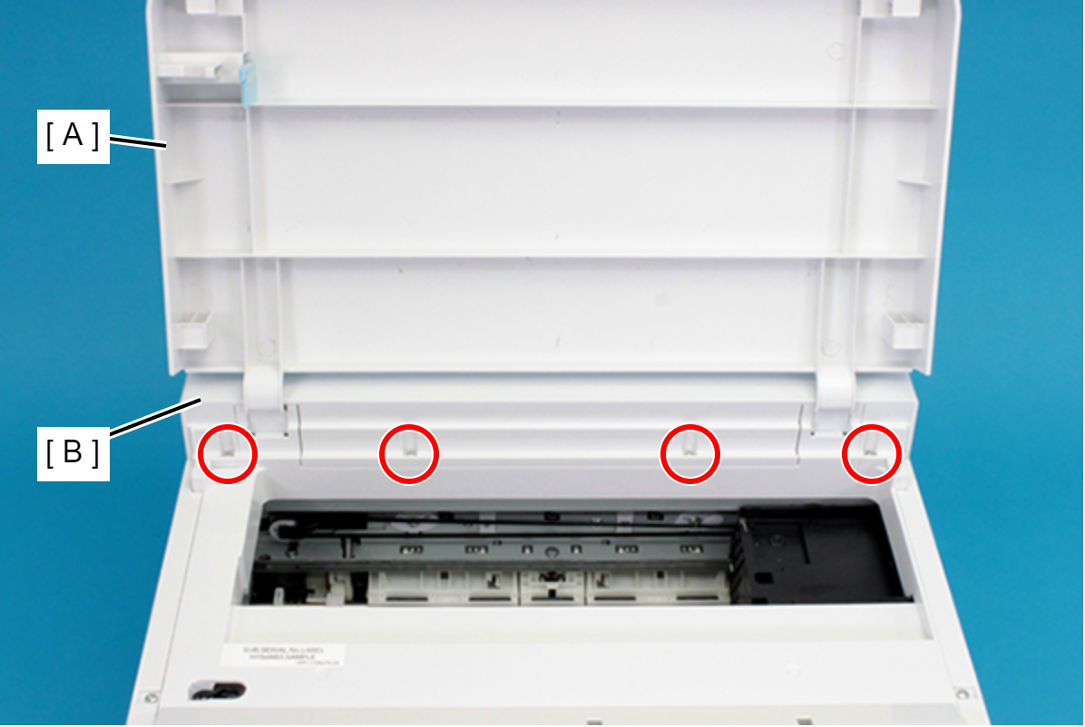
- Push the lever (A) of the Front Cover Open Sensor and secure it with tape (B).
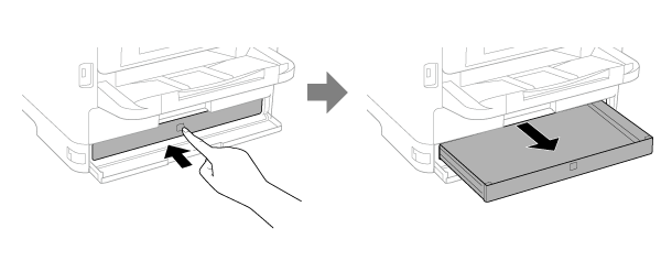
Press to pull out the Ink Pack Tray BK (A), and confirm that the Panel LCD is in normal condition, and not in an error state such as a “Front cover open error”.
Connect the PC and printer using a USB cable and start the adjustment program, and from the adjustment program menu, select “Ink eject” and press the Perform button.
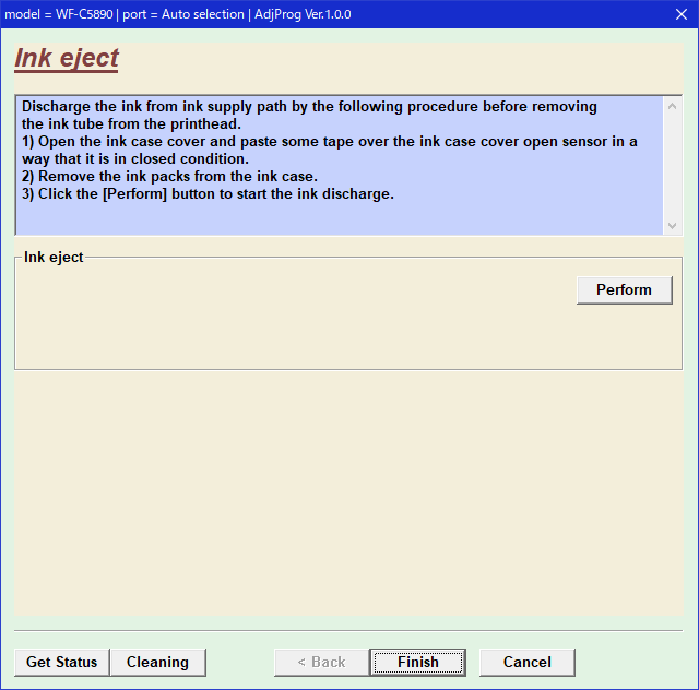
After finishing the Ink Discharge, disconnect the AC cable from the printer to turn the printer off.
Check Point / チェックポイントDo not turn OFF the power by pressing the power button as that may cause ink to be re-charged.
Since the amount of consumption of ink is not counted, take note of the amount of ink remaining in the Maintenance Box during Ink Discharge.
If the printer has entered sleep state by the time Ink Discharge is executed, an “Ink cartridge not installed error” will be generated as a result of the sequence at recovery from sleep state. Lengthen the sleep setting time in advance.
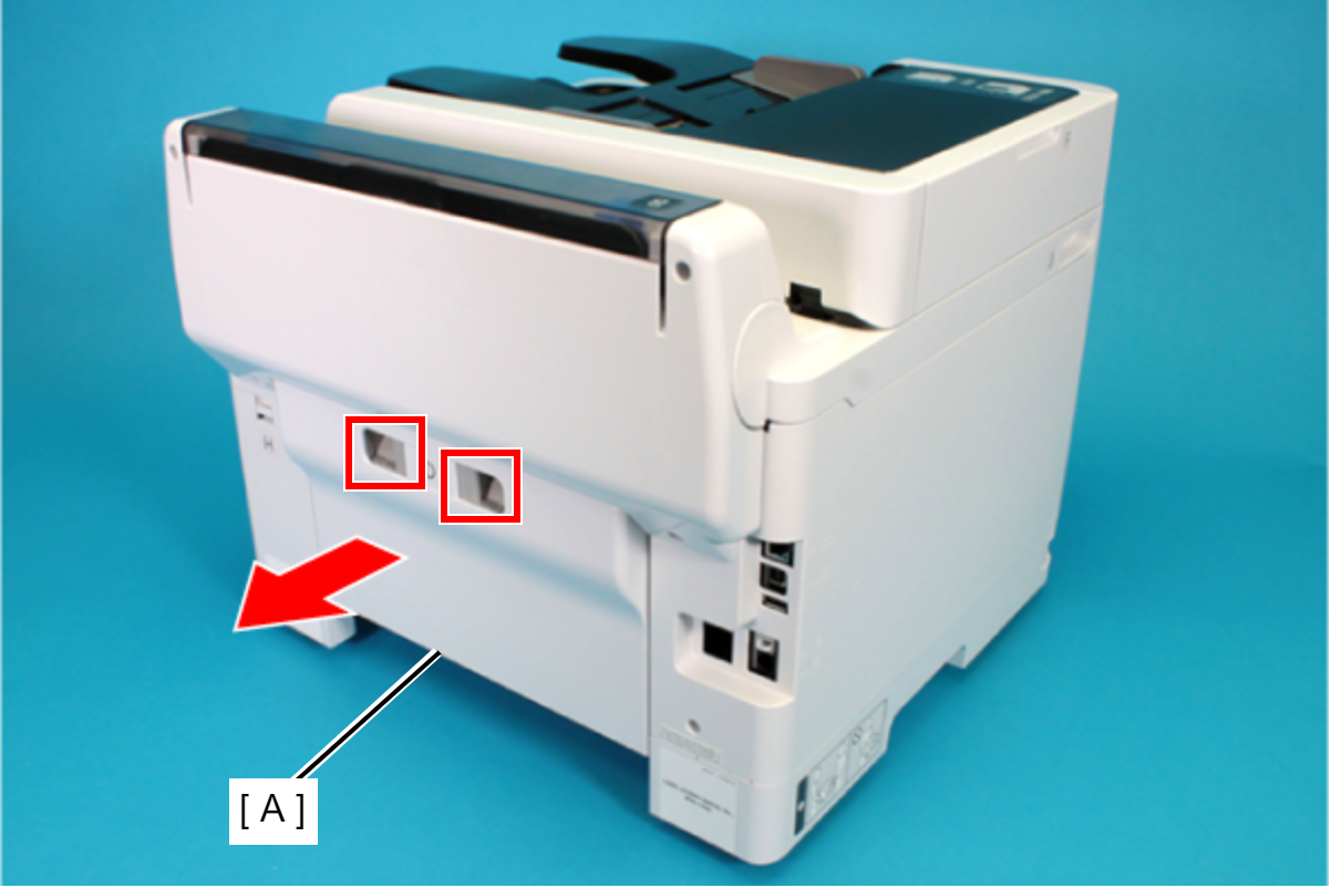
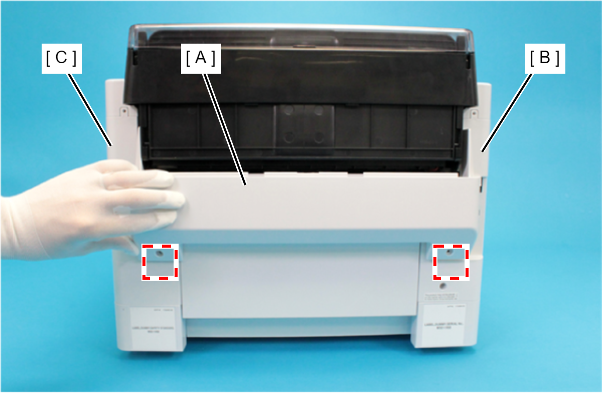
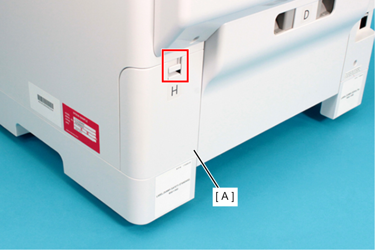
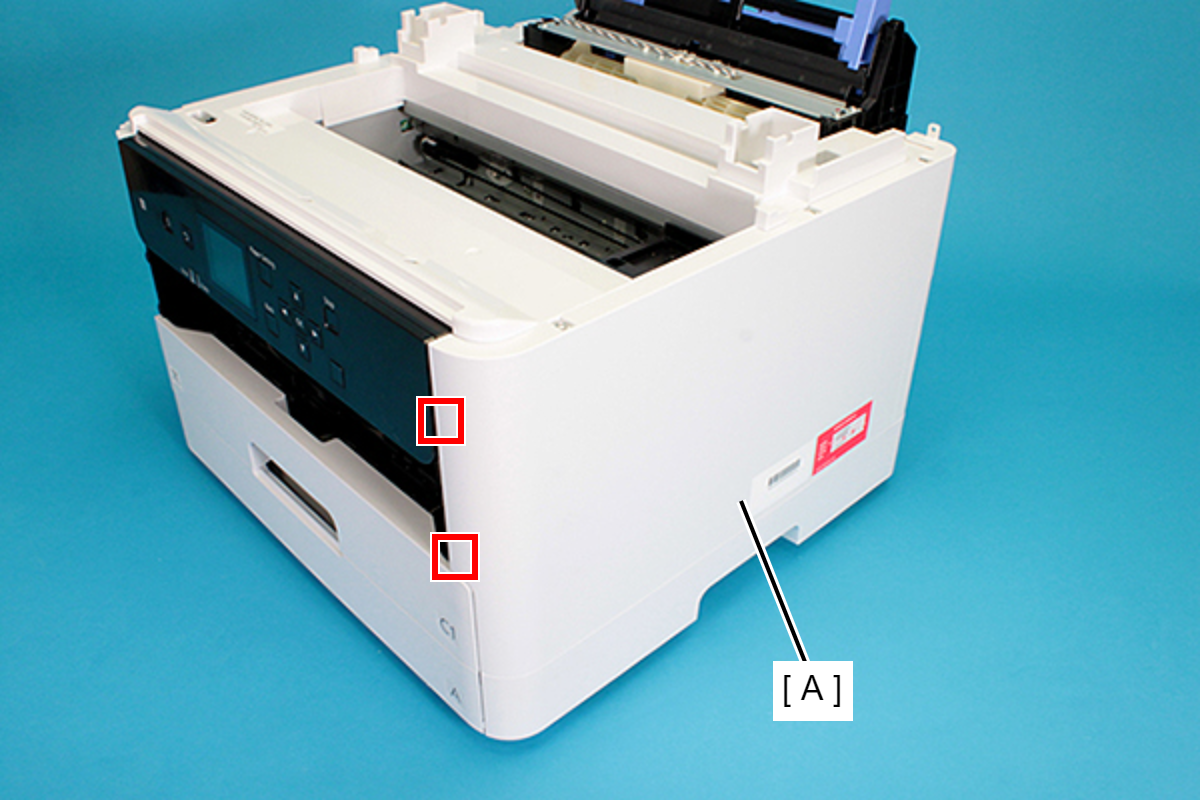
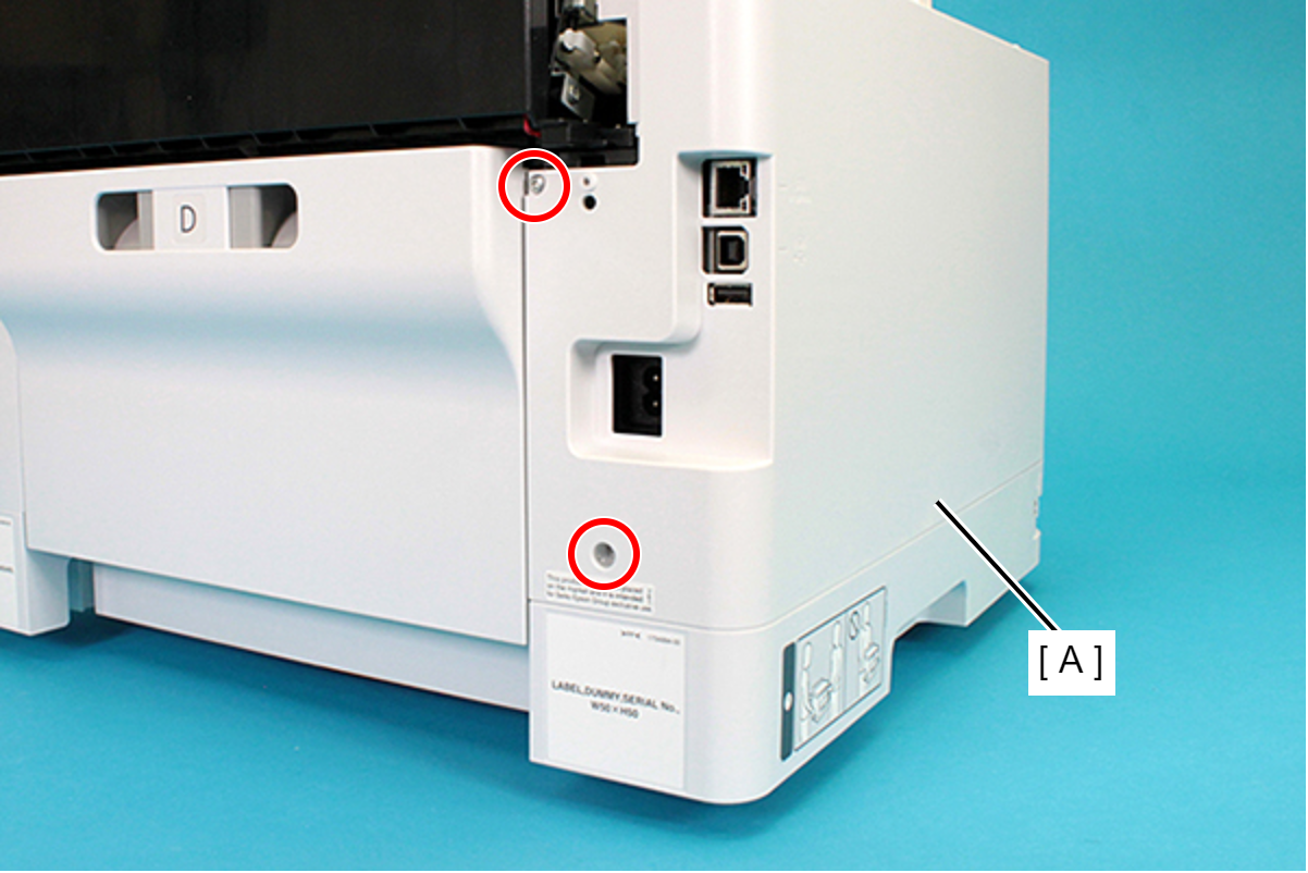
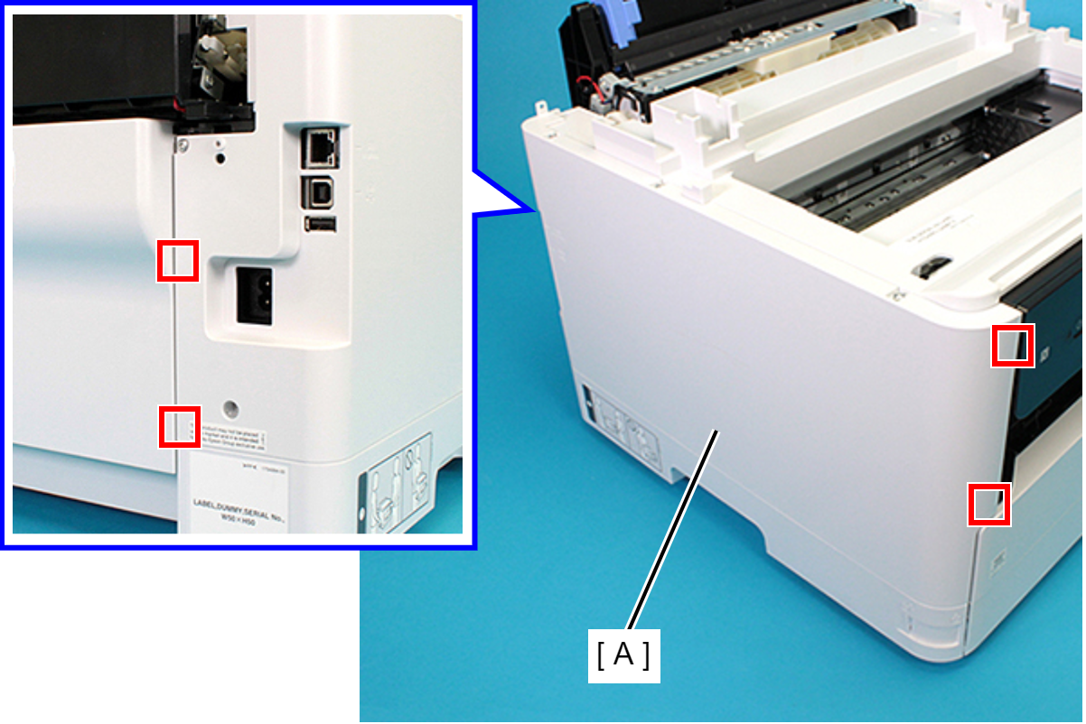
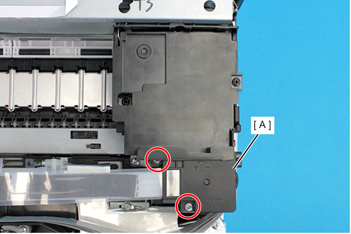
- Remove the Rear Unit (A) in the direction of the arrow while pressing the buttons inward.
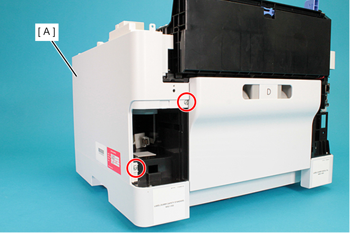
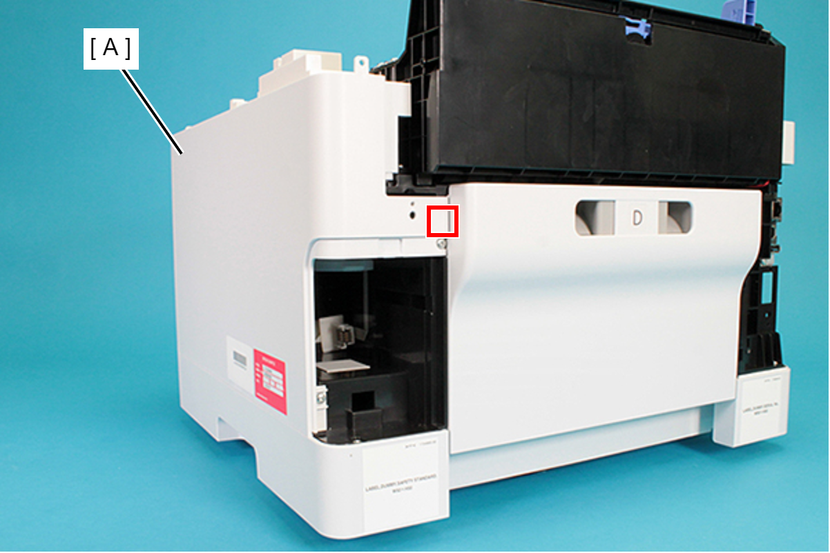
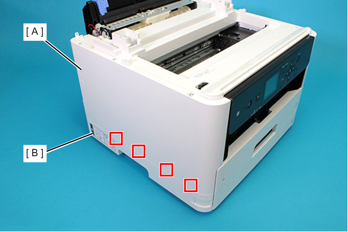
- Open the ASF Cover (A) and remove the two screws securing the Rear Housing Assy (B).
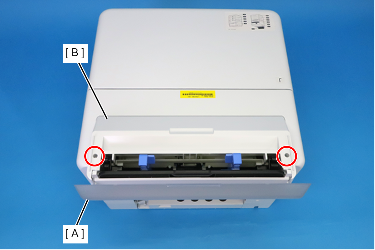
 : C.B.P-TITE-SCREW-3x10-F.ZB-3C
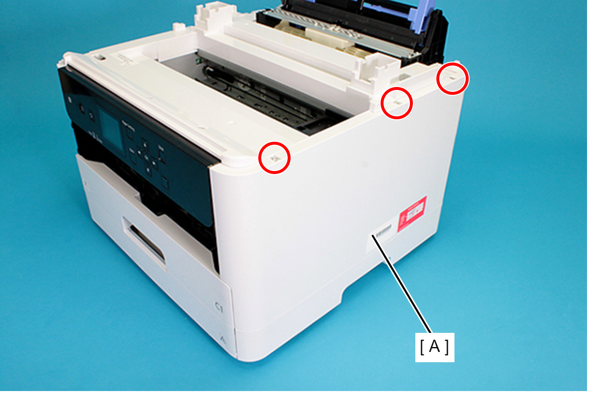
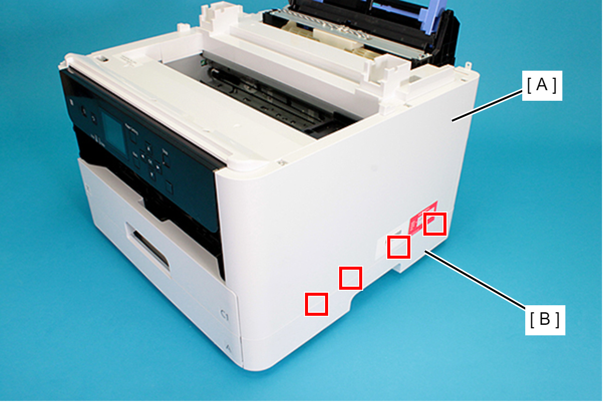
- Remove the four screws securing the Rear Housing (A).
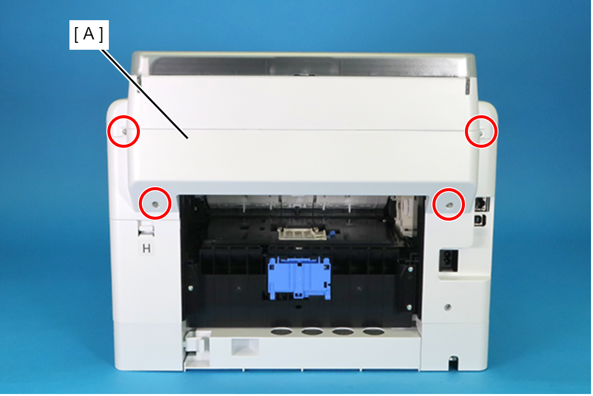
 : C.B.P-TITE-SCREW-3x10-F.ZN-3C
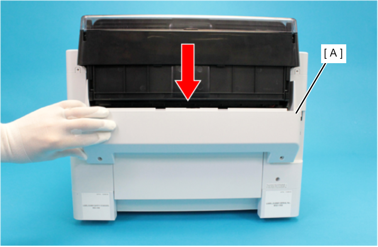
Remove the Rear Housing (A) downward.
 Assembly / 組み立て
Attach the two dowels of the Rear Housing (A) to the positioning holes on the Housing Left (B) and the Housing Right (C).
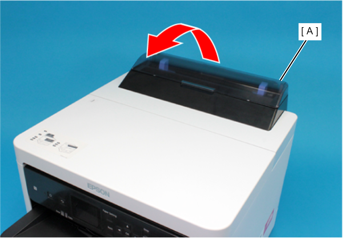
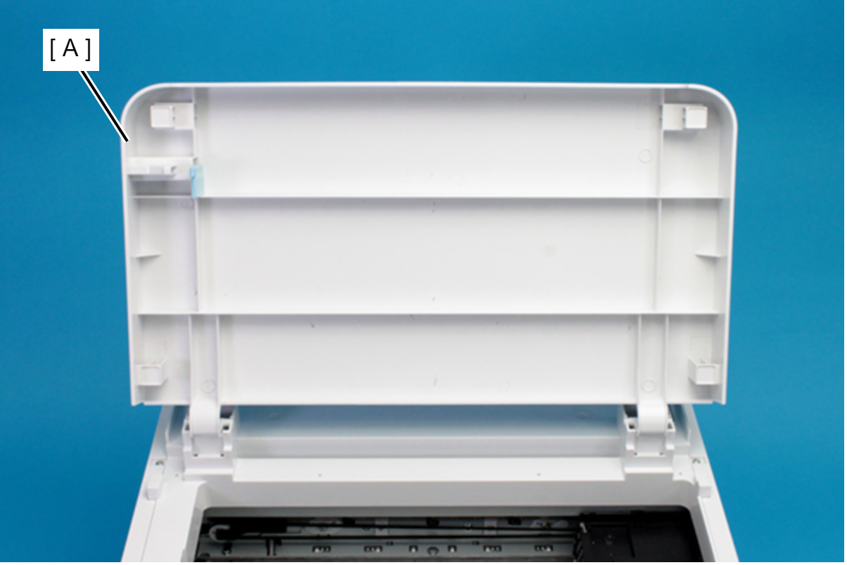
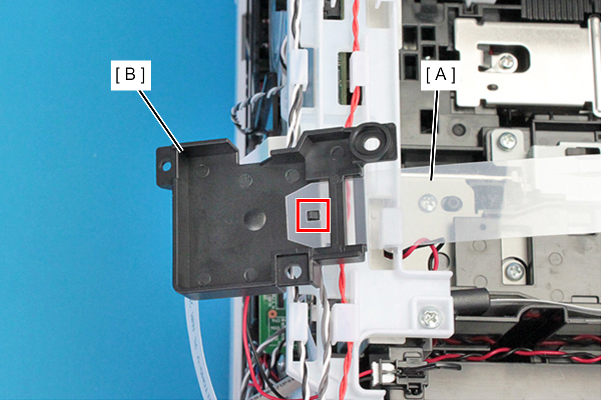
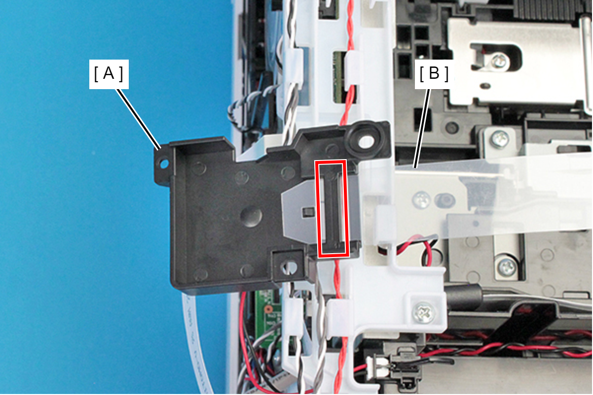
Remove the Rear Upper Cover Assy (A) in the direction of the arrow.
 Assembly / 組み立て
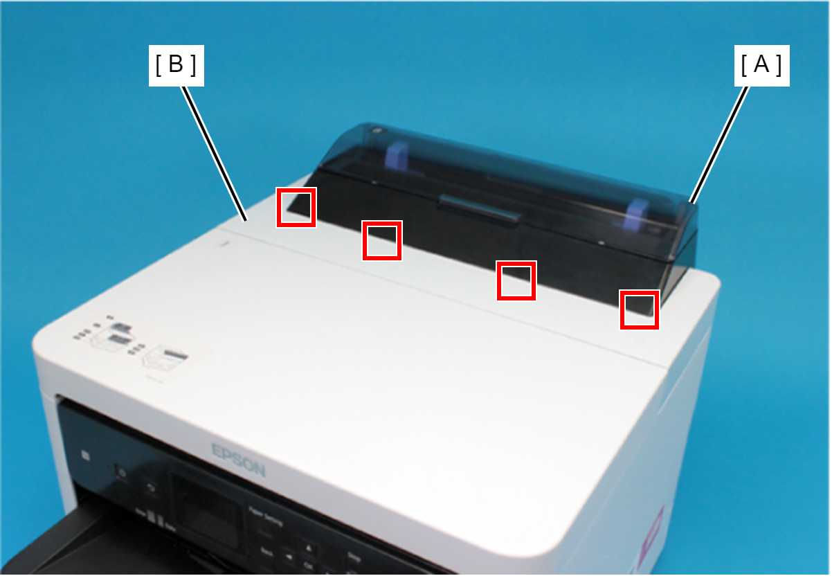
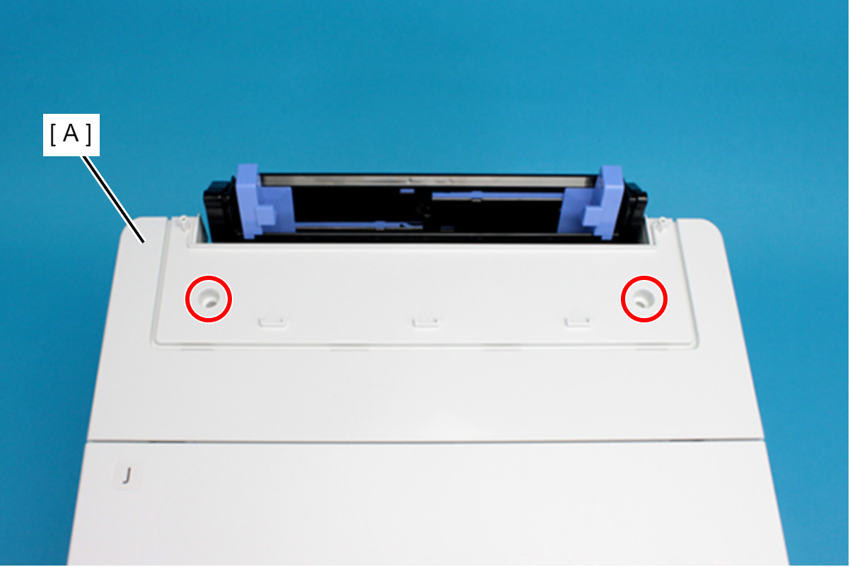
Insert the four tabs of the Rear Upper Cover Assy (A) to the positioning holes of the Housing ASF (B).
- Remove the two screws securing the Housing ASF (A).
- : C.B.P-TITE-SCREW-3x10-F.ZN-3C
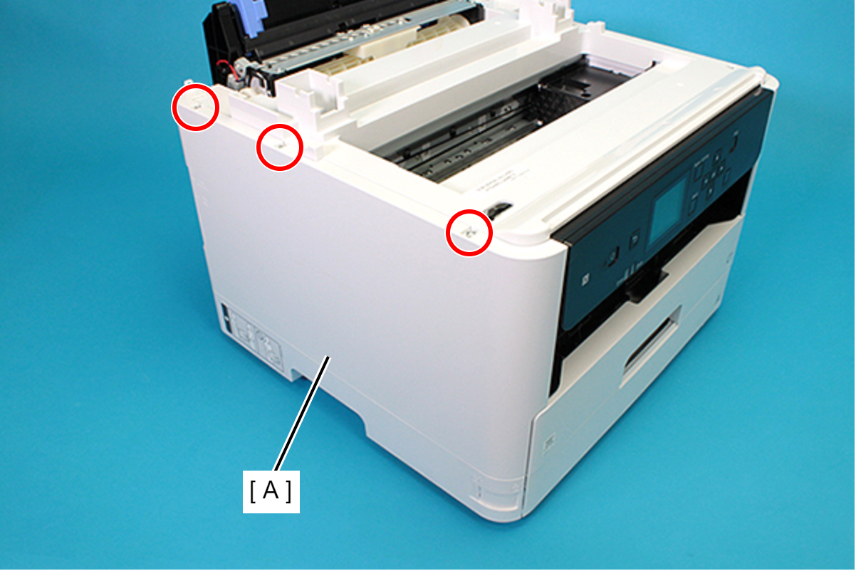
- Open the Printer Cover (A) and remove the four screws, and then remove the Housing ASF (B).
- : C.B.P-TITE-SCREW-3x10-F.ZN-3C
- Disengage the hook, and remove the Maintenance Box Cover (A).
- Remove the three screws securing the Housing Right (A).
- : C.B.P-TITE-SCREW-3x10-F.ZN-3C
- Remove the two screws securing the Housing Right (A).
- : C.B.P-TITE-SCREW-3x10-F.ZN-3C
- Lift the Housing Right (A) upward to release the two hooks on the front side of the Housing Right (A).
Remove the dowels to the rear, and lift up the Housing Right (A) to remove it.
 Assembly / 組み立て
Insert the four tabs of the Housing Right (A) to the positioning holes of the RIPS Unit (B).
- Remove the three screws securing the Housing Left (A).
- : C.B.P-TITE-SCREW-3x10-F.ZN-3C
- Remove the two screws securing the Housing Left (A).
- : C.B.P-TITE-SCREW-3x10-F.ZN-3C
Lift the Housing Left (A) upward to release the two hooks each on the front side and rear side of the Housing Left (A), and then remove the Housing Left (A).
 Assembly / 組み立て
Insert the four tabs of the Housing Left (A) to the positioning holes of the RIPS Unit (B).
- Remove the Printer Cover (A) upward.
- Remove the seven screws and remove the Housing Top (A).
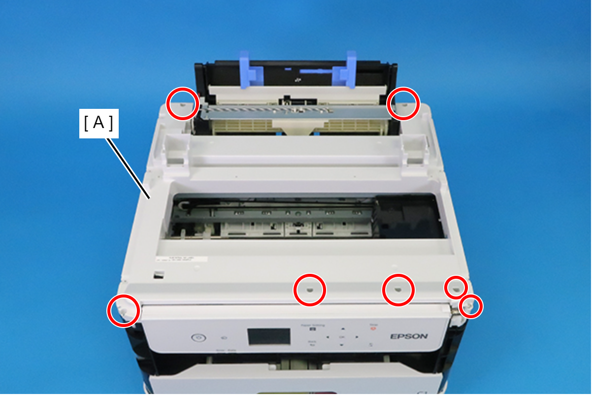
- : C.B.P-TITE-SCREW-3x10-F.ZN-3C
- Release the FFC (A) from the three hooks.
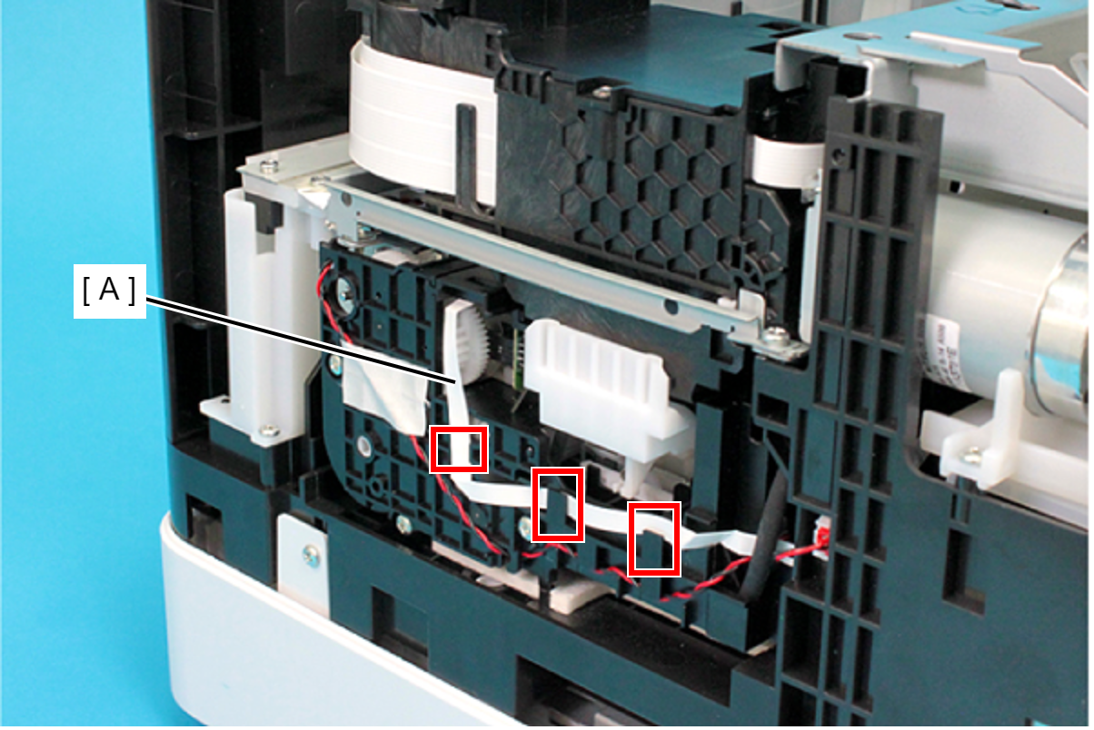
Rotate the gear (B) of the Ink System Unit (A) in the direction of the arrow, and move the CR Unit (C) to the left side.
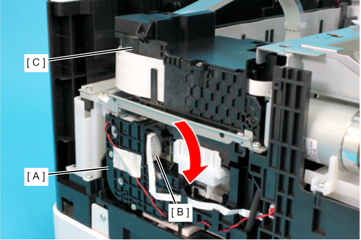
 Caution / 注意
When rotating the gear of the Ink System Unit, take extra care not to damage or disconnect the FFC by touching it.
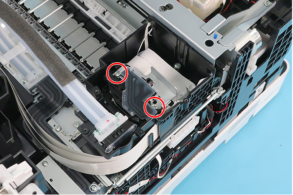
- Remove the two screws, and then remove the Head Upper Cover (A).
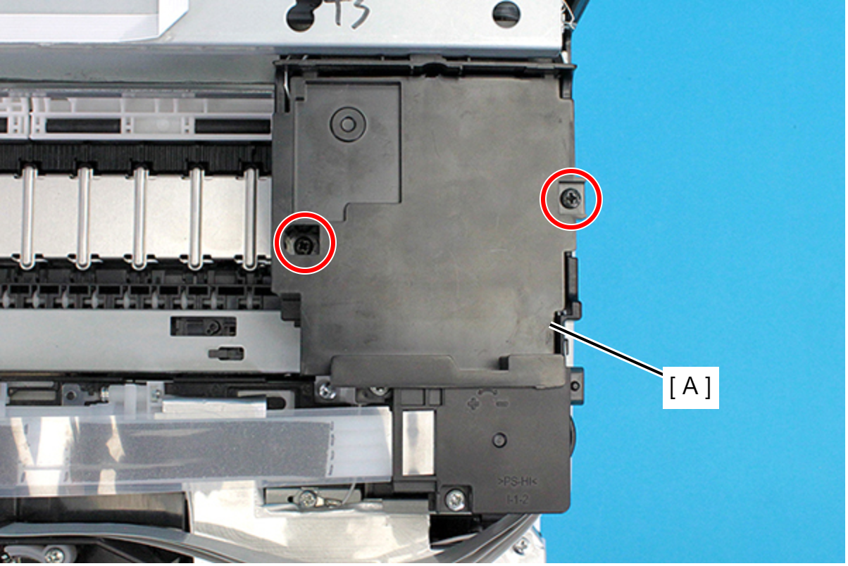
- : C.B.P-TITE-SCREW-3x10-F.ZB-3C
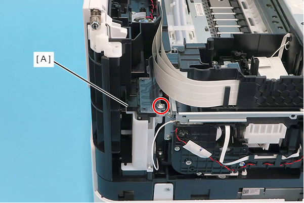
- Remove the two screws, and remove the Ink Tube Joint Cover (A).
- : C.B.P-TITE-SCREW-3x10-F.ZN-3C
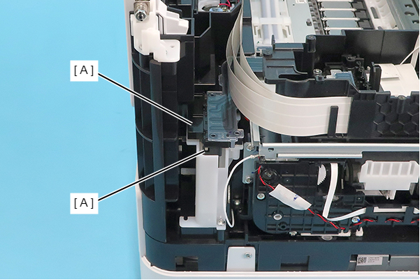
Remove the film (A) from the hook and remove the Ink Tube Joint Cover (B).
 Assembly / 組み立て
Set the film (B) under the rib of the Ink Tube Joint Cover (A).
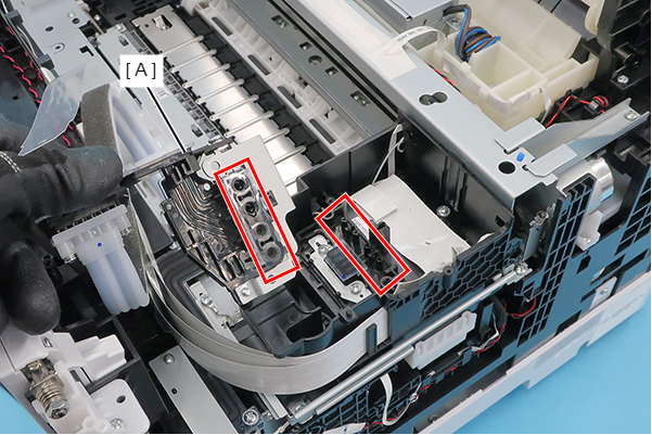
Remove the two Bind Screw3 x 12 (w/washer).
Remove the Ink Supply Tube (A) by pulling it straight in the direction of the arrow.
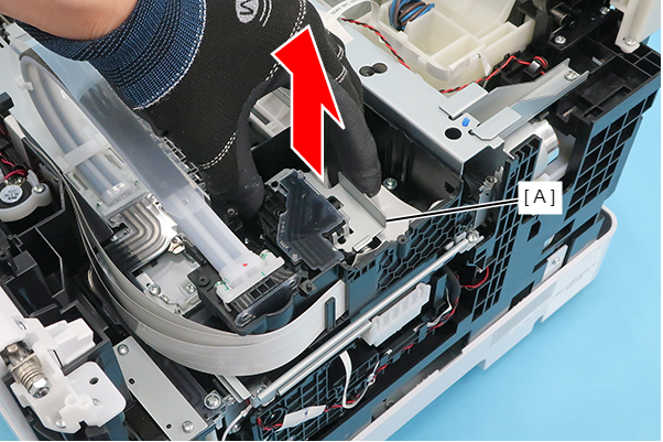 Caution / 注意
Ink may spill from the Ink Supply Tube. Prepare waste cloths or similar in advance.
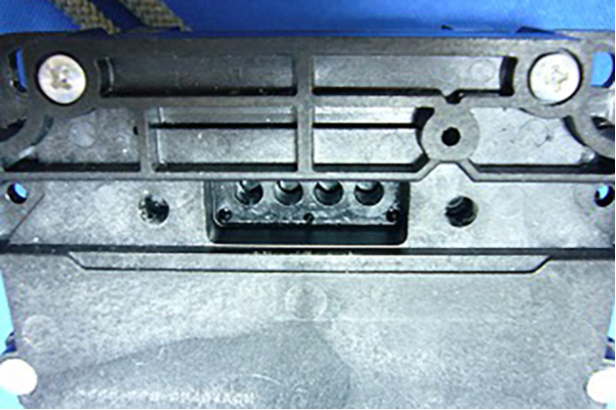
Assembly / 組み立てWhen attaching the ink Supply Tube (A), insert the four nozzles into each of the four connection holes, and insert them all the way in.
Remove the two Bind Screw2.5 x 20 (w/washer).
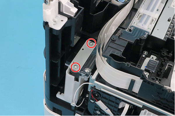
Remove the Plate (A).
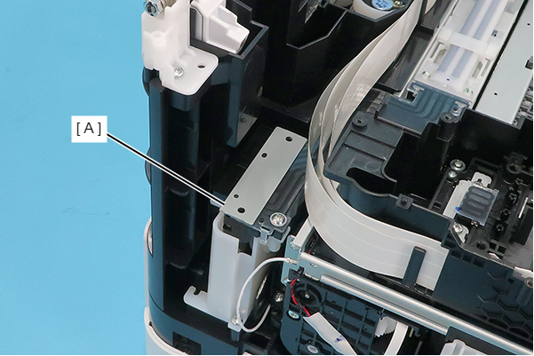 Caution / 注意
In the following steps, ink may spill from the Ink Supply Tube. Prepare waste cloths or similar in advance.
Remove the Ink Tube (B) from the Tube Clamp (A).
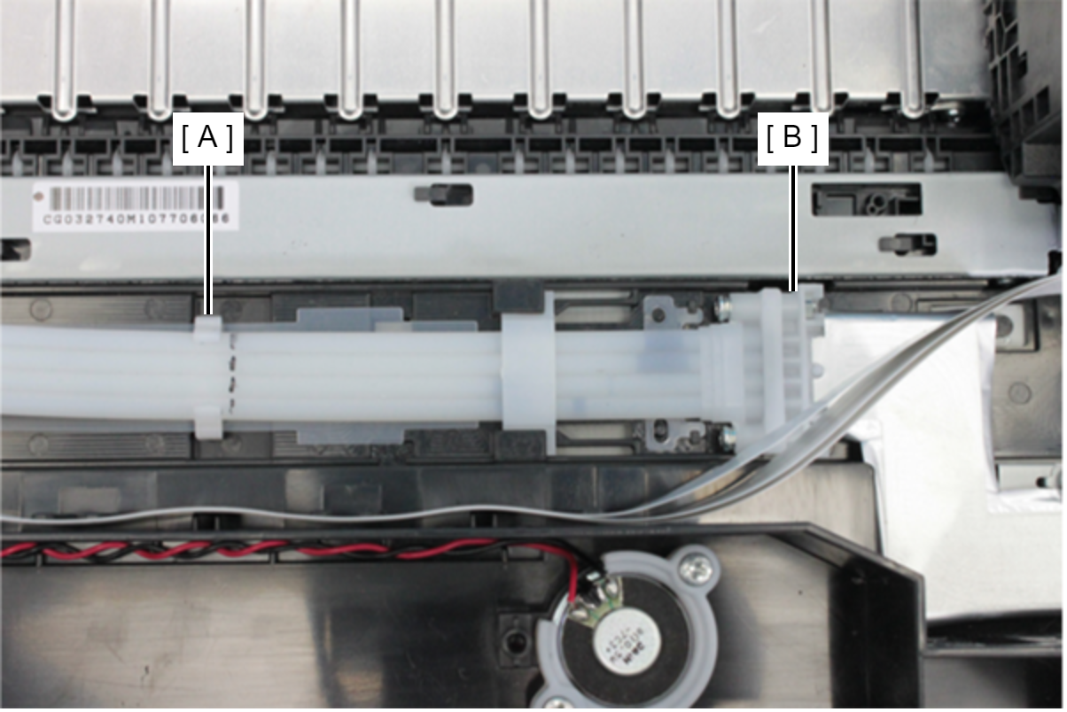 Assembly / 組み立て
- At the marking point on the Ink Supply Tube (A), attach the Ink Supply Tube (A) to the Tube Clamp (B).
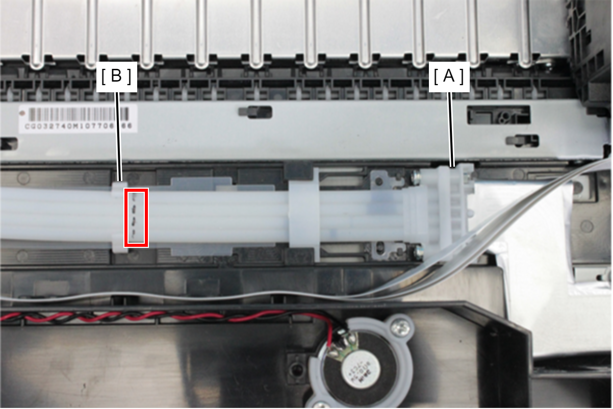
- If the marking is not visible, refer to the figure below.
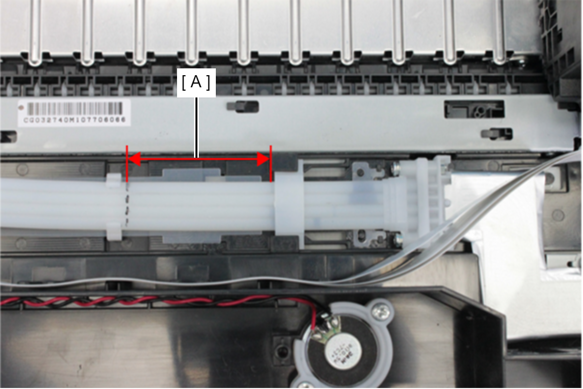
- Length of (A): 87.5 ± 1 mm
- At the marking point on the Ink Supply Tube (A), attach the Ink Supply Tube (A) to the Tube Clamp (B).
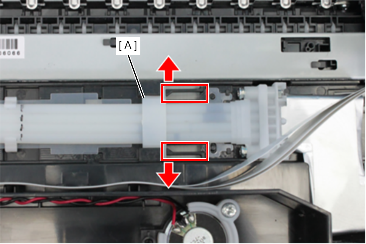
- Remove the Tube Holder (A) while pressing the hooks outward.
- Remove the screw that secure the Ink Supply Tube (A).
- : C.B.P-TITE-SCREW-3x10-F.ZN-3C
Remove the Ink Supply Tube (B) from the Joint (A), and remove the Ink Supply Tube (B).
 Caution / 注意
If ink is remained to ink tube joint part of Printhead, Ink Leak Check can not perform correctly. Therefore cleaning the ink surely.
Assembly / 組み立て- In order to obtain correct results from the Ink Leak Check, the ink tube joint part of the Printhead need to be cleaned.
Make sure to clean the Ink tube joint part of Printhead by using the Cleaning stick, because perform the Ink Leak Check correctly.
If ink is remained to ink tube joint part of Printhead, Ink Leak Check can not perform correctly. Therefore cleaning the ink surely.
-
- Rear Section
- Right side
- Bottom
- Left side
- Front Section
- Rear Section
In this product, Ink Leak Check is necessary to prevent the ink leakage due to assembly mistake.
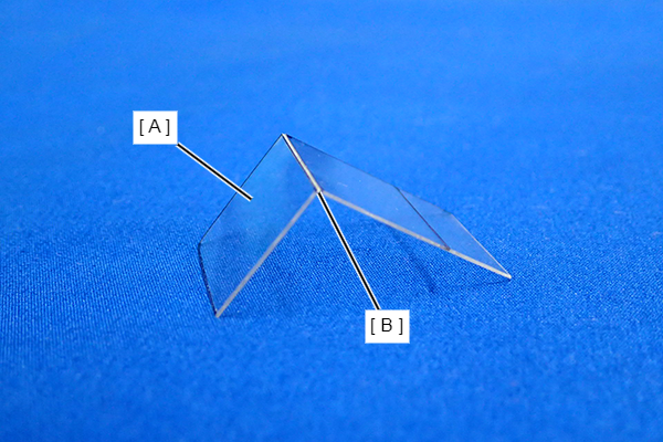
Therefore, make sure to install the Ink Leak Check Jig when installing the Ink Tube to Printhead.Types of Ink Leak Check Jigs.
Parts name Part code Length of figure below (A) Remarks LEAK TESTER SHEET REAR 1684354 16.5 mm One side only has a smoky surface (B). 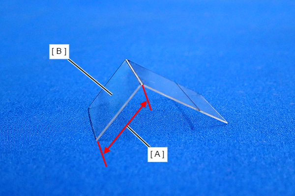
Install the Ink Leak Check Jigs in accordance with the following procedure.
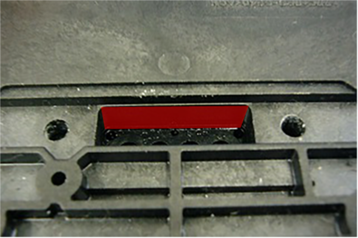
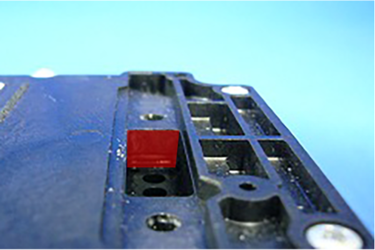
- Before using the Ink Leak Check Jig (A), push the Ink Leak Check Jigs along the fold until the fold angle become 90 degrees.
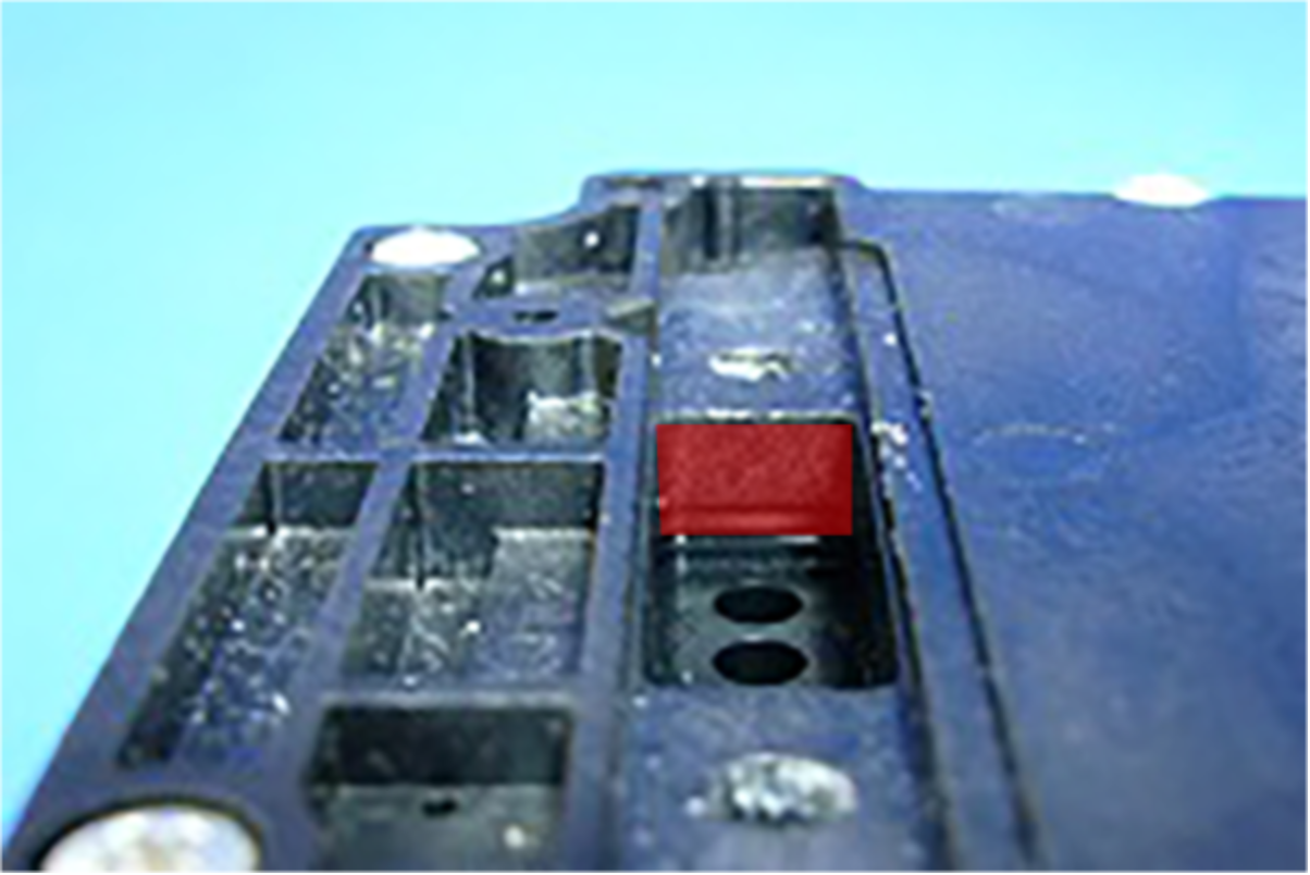
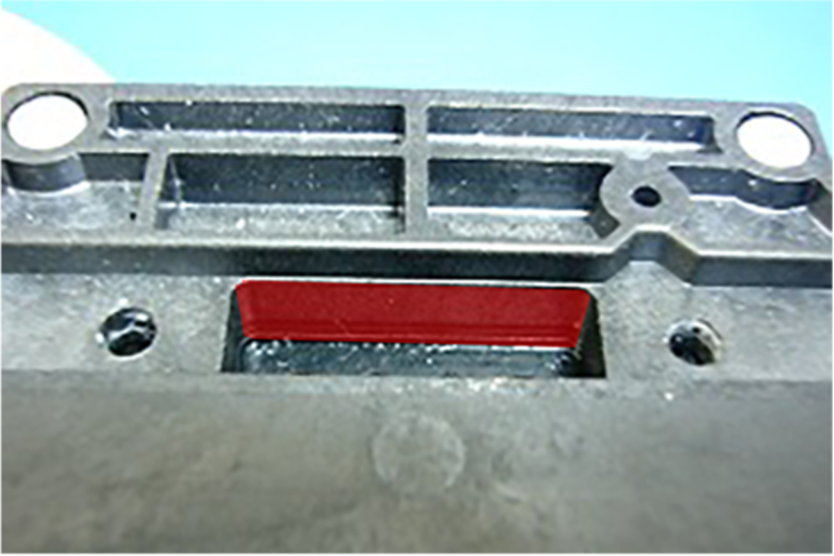
- Set the LEAK TESTER SHEET REAR (A) in the gap (B) of the Head Attachment with the smoky surface (C) upwards.
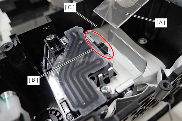
Make sure that the folded part (B) of the LEAK TESTER SHEET REAR (A) does not stick out.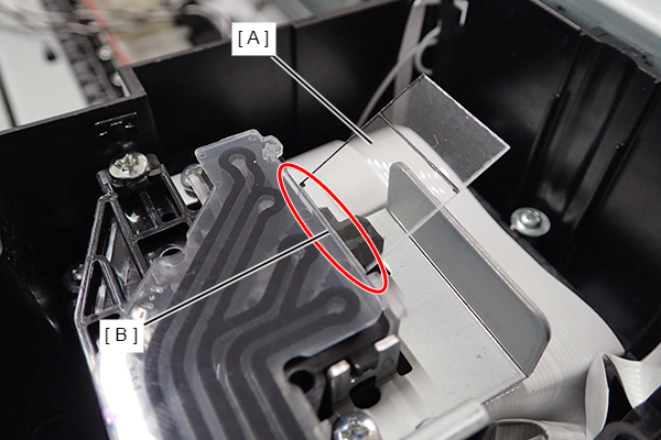
Attach the Head Upper Cover (A).

- Before using the Ink Leak Check Jig (A), push the Ink Leak Check Jigs along the fold until the fold angle become 90 degrees.
Adjustment / 調整After ink charging, follow the instructions on the Ink leak check to remove the LEAK TESTER SHEET REAR, then perform Leak Check Judgement.
- In order to obtain correct results from the Ink Leak Check, the ink tube joint part of the Printhead need to be cleaned.