RIPS Unit Lower (WF-M5399 Series)
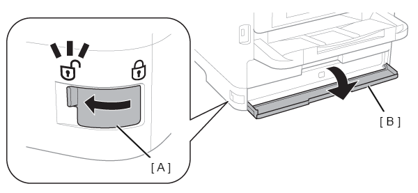
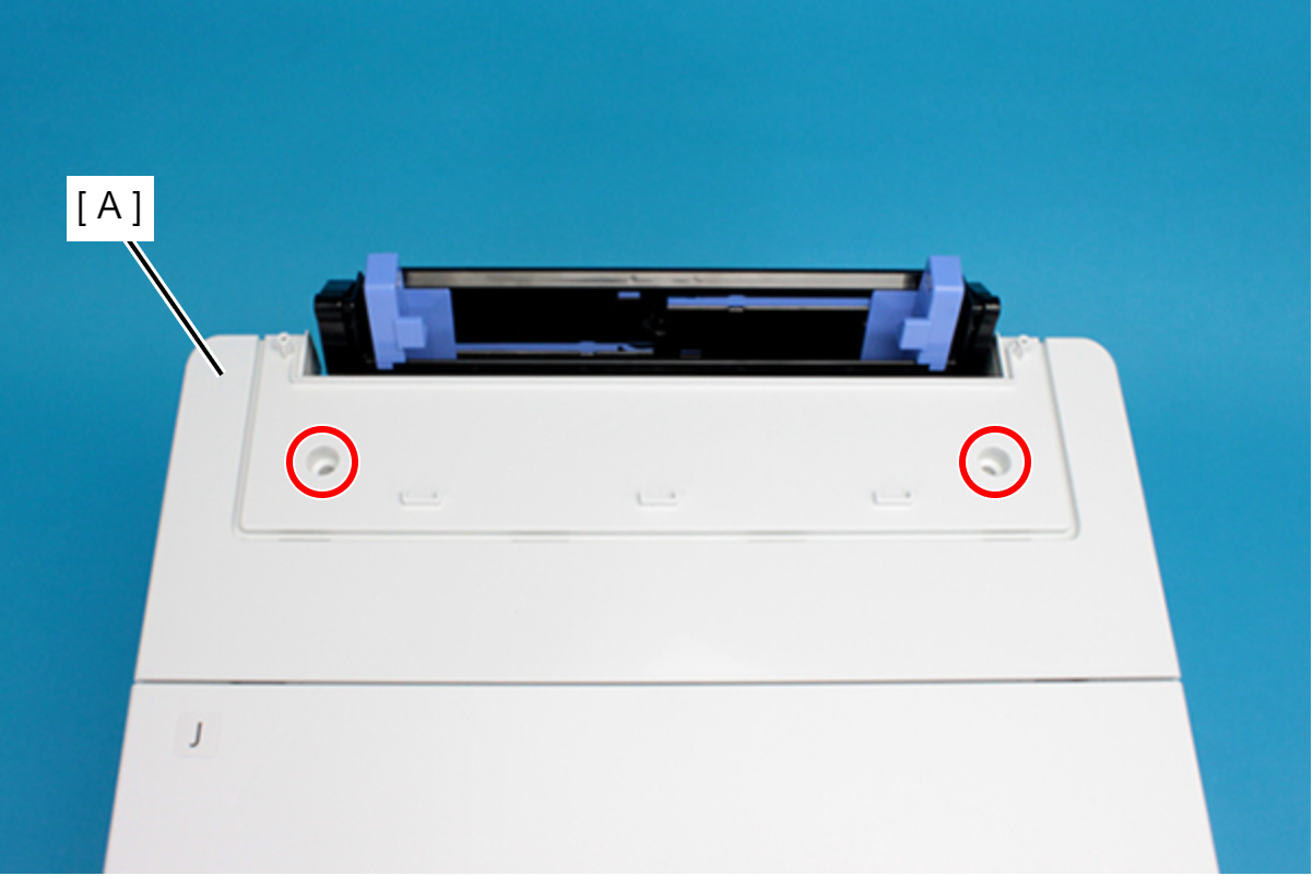
With the printer power ON, move the Lock Lever (A) in the direction of the arrow, and open the Ink Pack Cover (B).
 Check Point / チェックポイント
- In the next step, when securing the lever of the Cover Open Sensor with tape, secure it properly ensuring there is no peeling of the tape during adjustment. (If the tape peels, the “Cover open error” will occur and the adjustment process will be interrupted.)
- If Steps 2 and 3 are reversed, then sensor control within the printer will generate an “Ink cartridge not installed error”, and starting ink discharge work will not be possible.
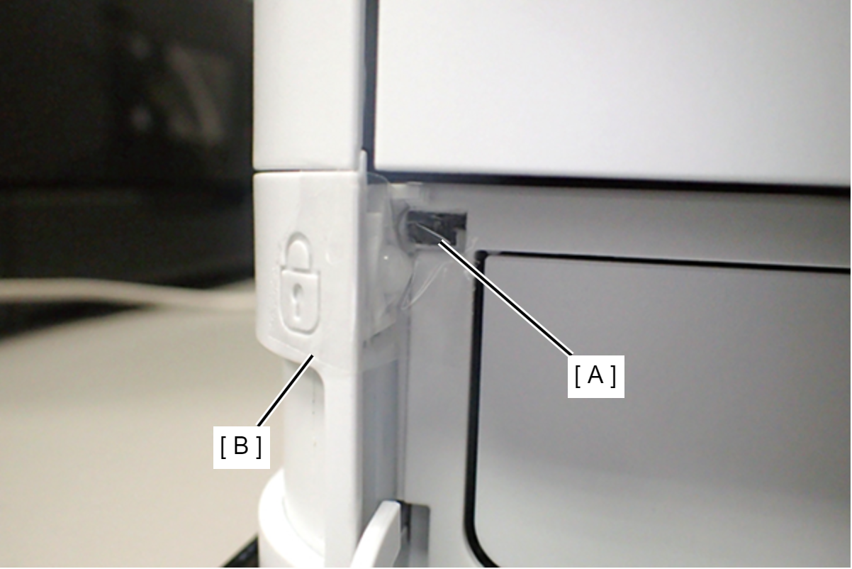
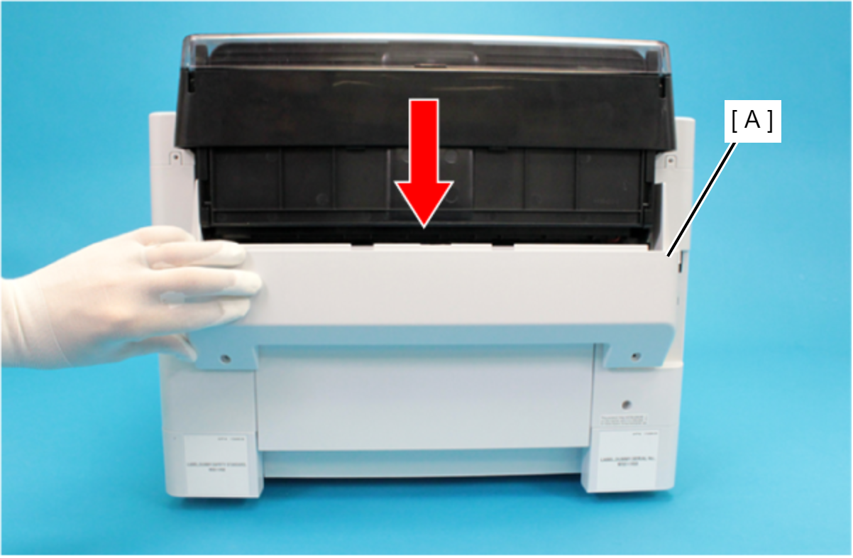
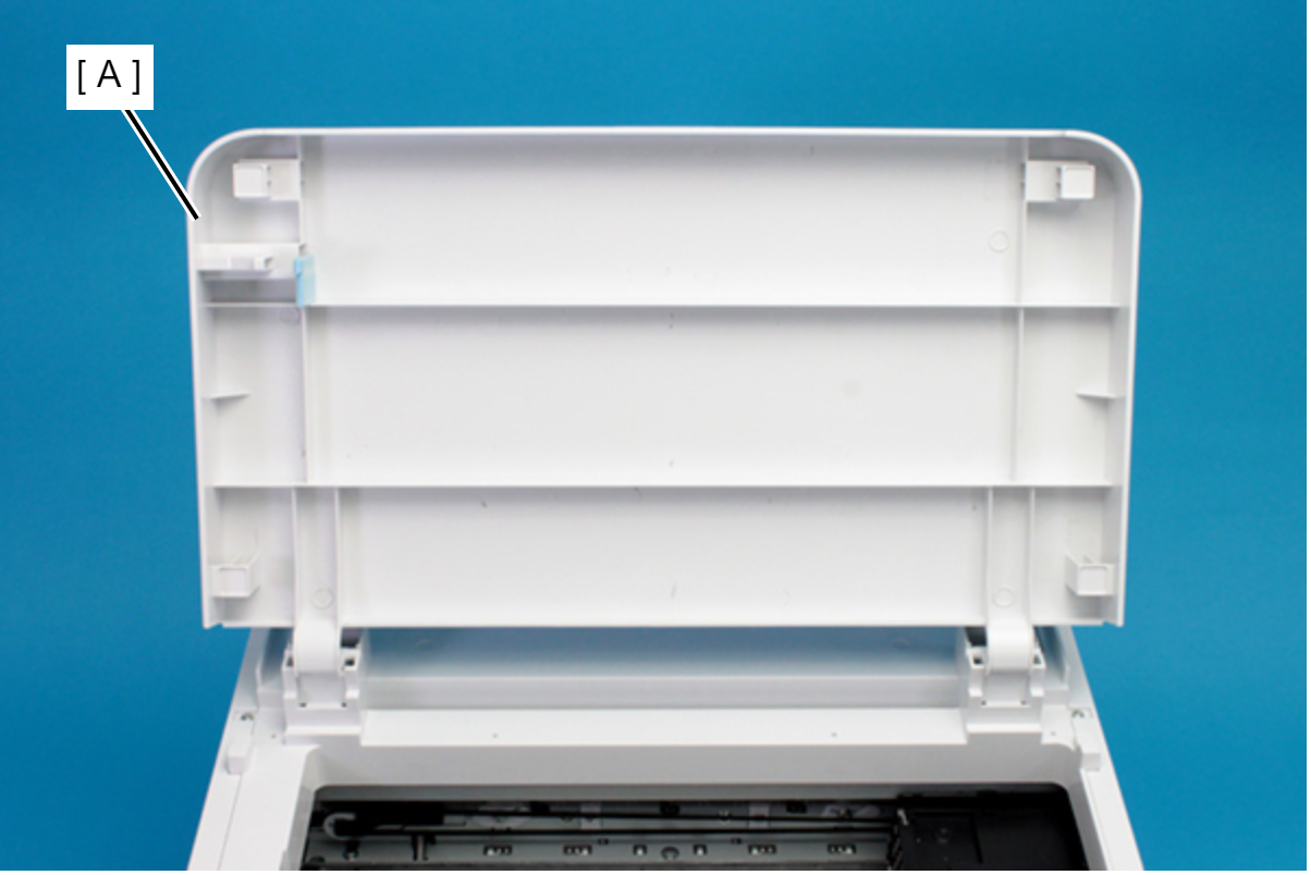
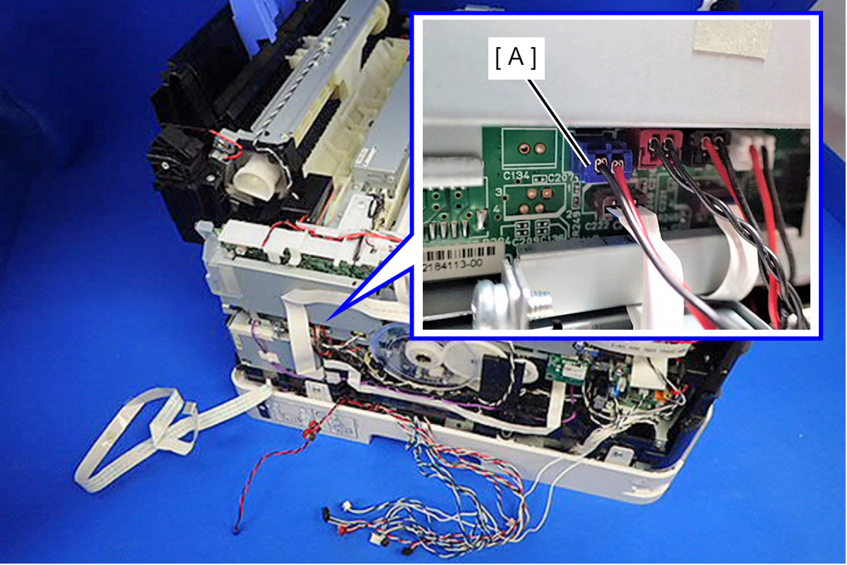
- Push the lever (A) of the Front Cover Open Sensor and secure it with tape (B).
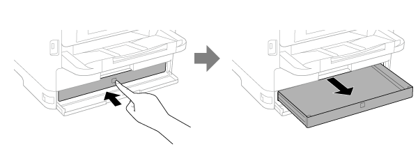
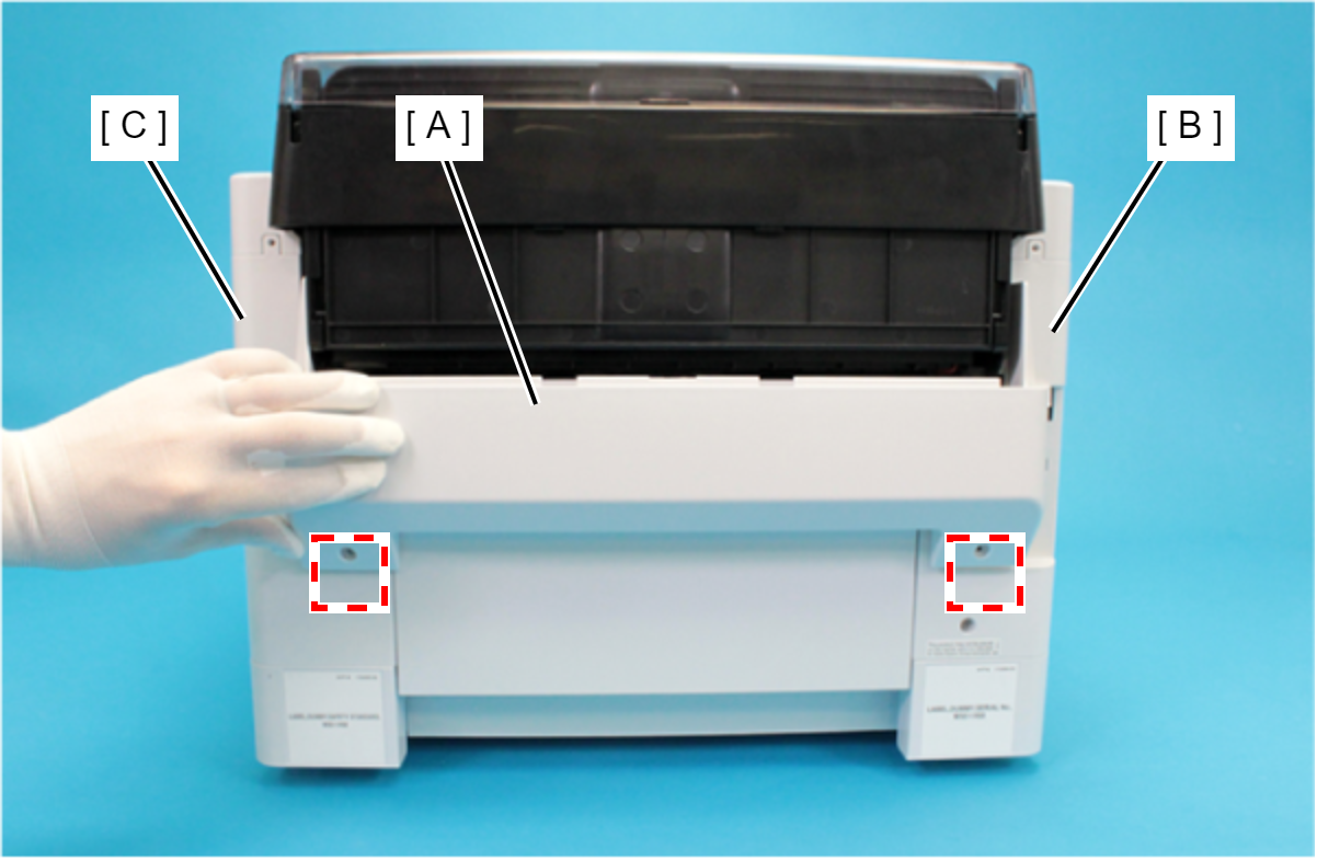
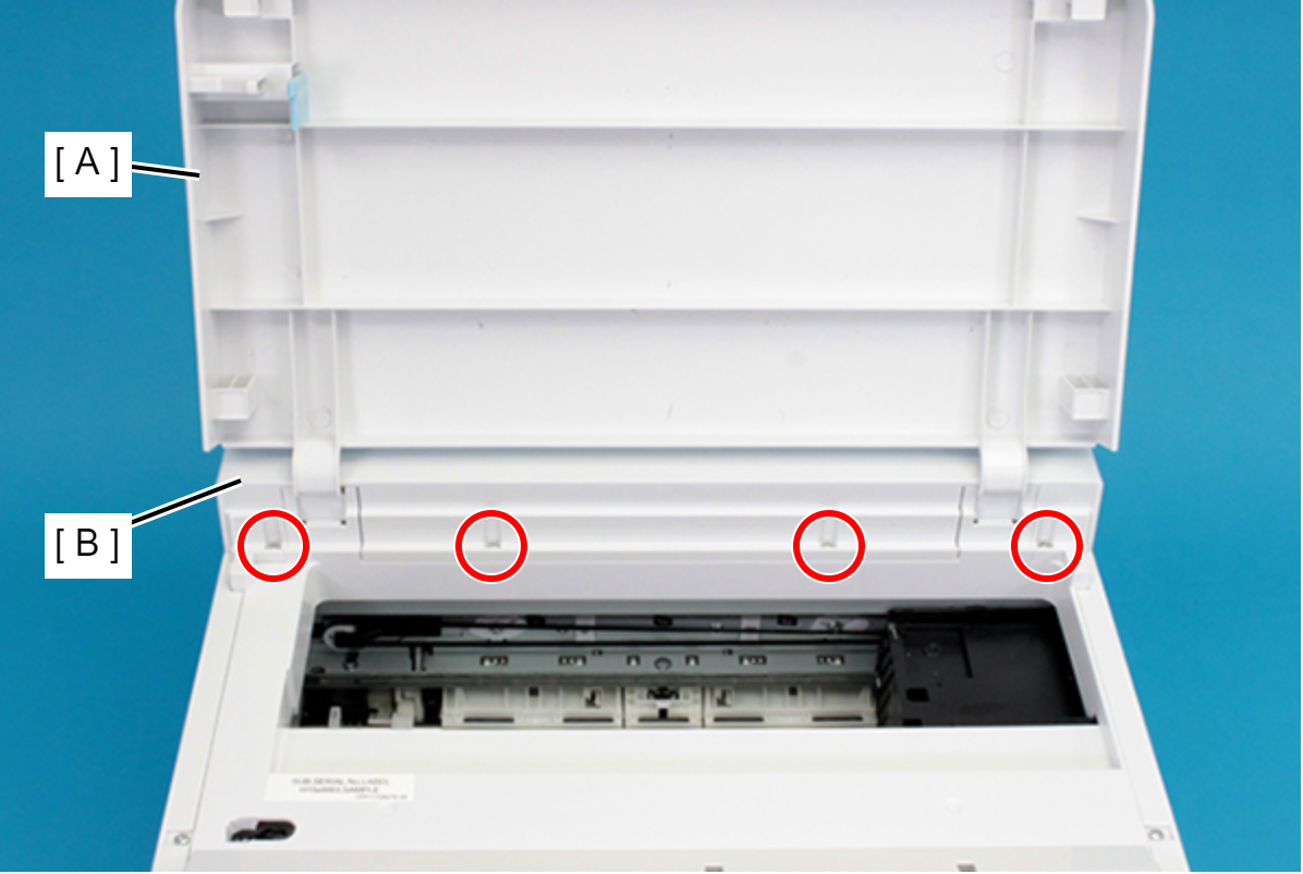
Press to pull out the Ink Pack Tray BK (A), and confirm that the Panel LCD is in normal condition, and not in an error state such as a “Front cover open error”.
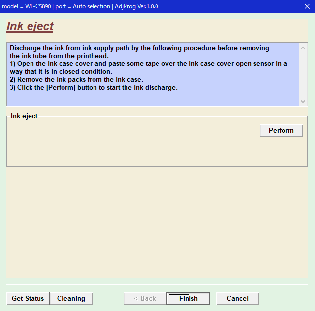
Connect the PC and printer using a USB cable and start the adjustment program, and from the adjustment program menu, select “Ink eject” and press the Perform button.
After finishing the Ink Discharge, disconnect the AC cable from the printer to turn the printer off.
Check Point / チェックポイントDo not turn OFF the power by pressing the power button as that may cause ink to be re-charged.
Since the amount of consumption of ink is not counted, take note of the amount of ink remaining in the Maintenance Box during Ink Discharge.
If the printer has entered sleep state by the time Ink Discharge is executed, an “Ink cartridge not installed error” will be generated as a result of the sequence at recovery from sleep state. Lengthen the sleep setting time in advance.
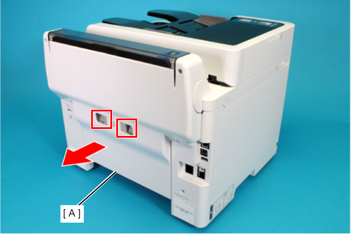
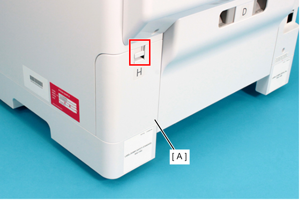
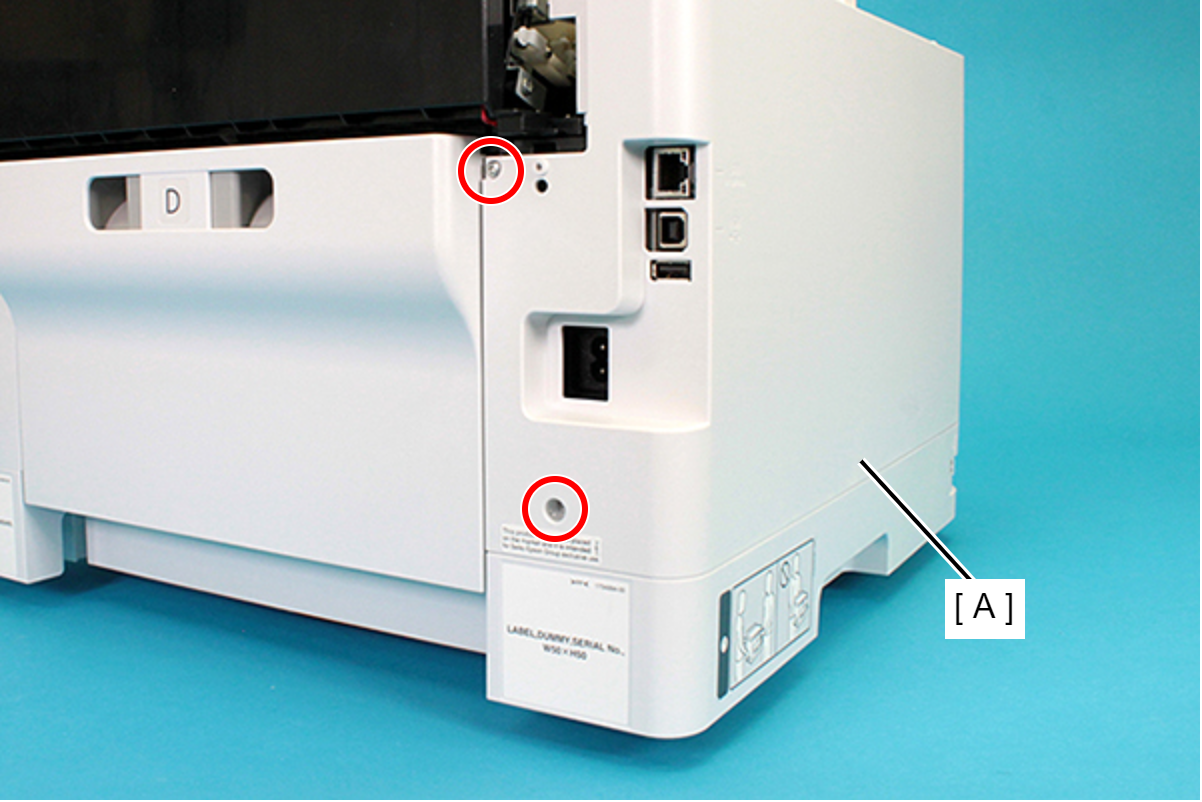
- Remove the Rear Unit (A) in the direction of the arrow while pressing the buttons inward.
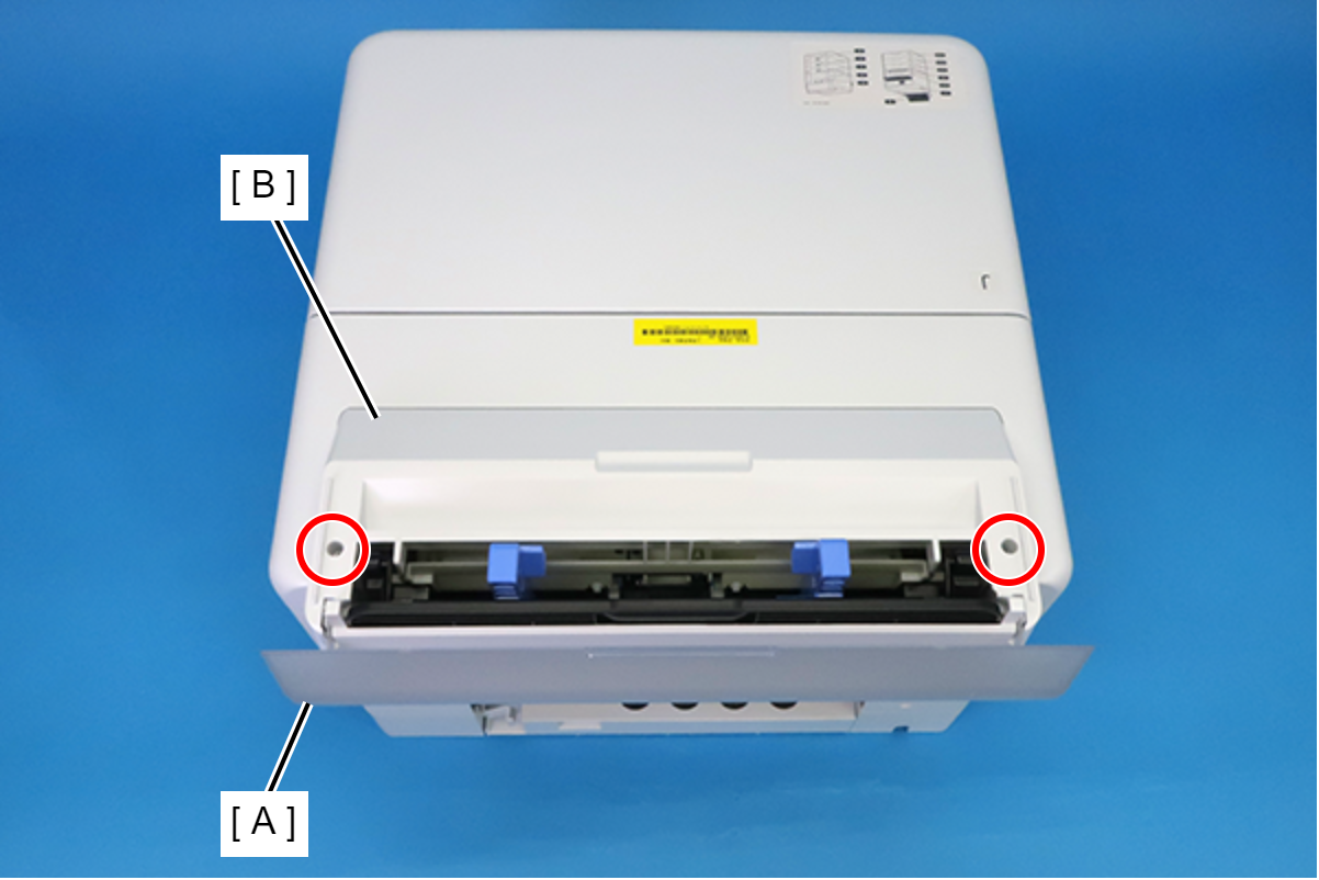
- Open the ASF Cover (A) and remove the two screws securing the Rear Housing Assy (B).
 : C.B.P-TITE-SCREW-3x10-F.ZB-3C
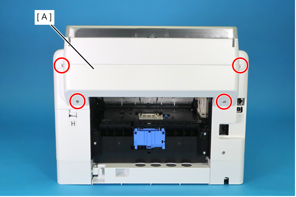
- Remove the four screws securing the Rear Housing (A).
 : C.B.P-TITE-SCREW-3x10-F.ZN-3C
Remove the Rear Housing (A) downward.
 Assembly / 組み立て
Attach the two dowels of the Rear Housing (A) to the positioning holes on the Housing Left (B) and the Housing Right (C).
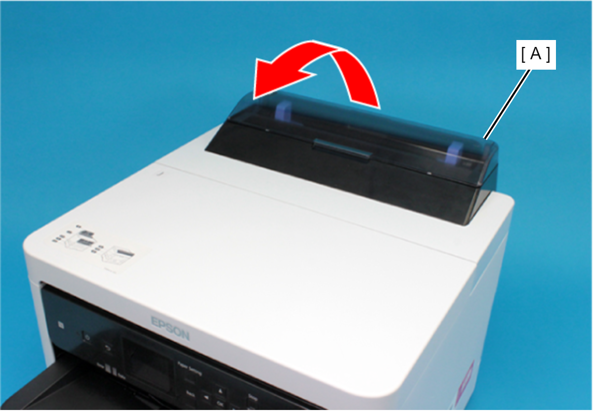
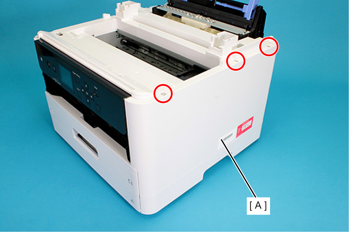
Remove the Rear Upper Cover Assy (A) in the direction of the arrow.
 Assembly / 組み立て
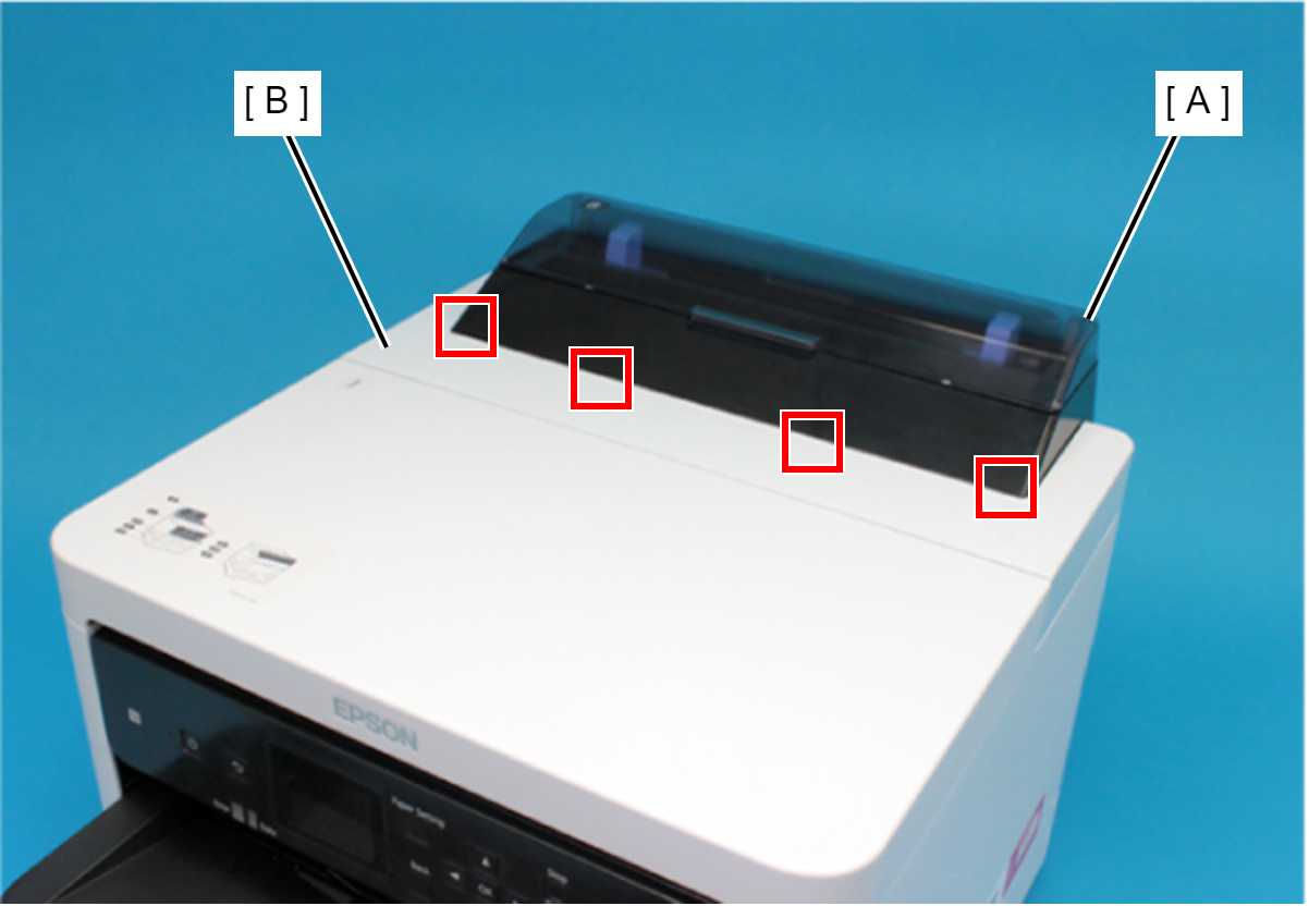
Insert the four tabs of the Rear Upper Cover Assy (A) to the positioning holes of the Housing ASF (B).
- Remove the two screws securing the Housing ASF (A).
- : C.B.P-TITE-SCREW-3x10-F.ZN-3C
- Open the Printer Cover (A) and remove the four screws, and then remove the Housing ASF (B).
- : C.B.P-TITE-SCREW-3x10-F.ZN-3C
- Disengage the hook, and remove the Maintenance Box Cover (A).
- Remove the three screws securing the Housing Right (A).
- : C.B.P-TITE-SCREW-3x10-F.ZN-3C
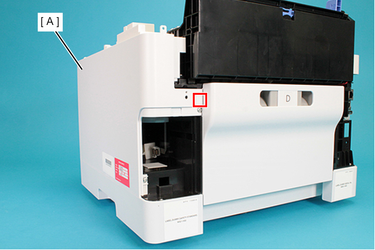
- Remove the two screws securing the Housing Right (A).
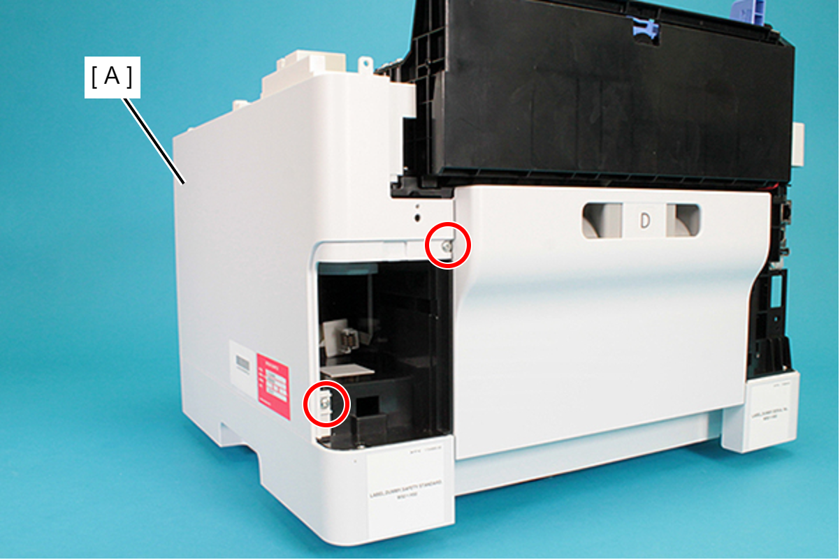
- : C.B.P-TITE-SCREW-3x10-F.ZN-3C
- Lift the Housing Right (A) upward to release the two hooks on the front side of the Housing Right (A).
Remove the dowels to the rear, and lift up the Housing Right (A) to remove it.
 Assembly / 組み立て
Insert the four tabs of the Housing Right (A) to the positioning holes of the RIPS Unit (B).
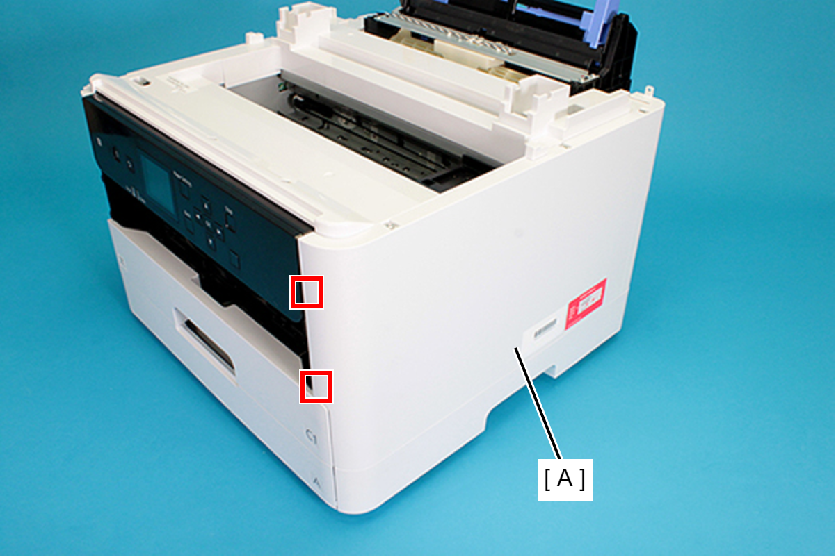
- Remove the three screws securing the Housing Left (A).
- : C.B.P-TITE-SCREW-3x10-F.ZN-3C
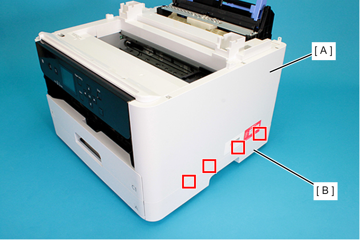
- Remove the two screws securing the Housing Left (A).
- : C.B.P-TITE-SCREW-3x10-F.ZN-3C
Lift the Housing Left (A) upward to release the two hooks each on the front side and rear side of the Housing Left (A), and then remove the Housing Left (A).
 Assembly / 組み立て
Insert the four tabs of the Housing Left (A) to the positioning holes of the RIPS Unit (B).
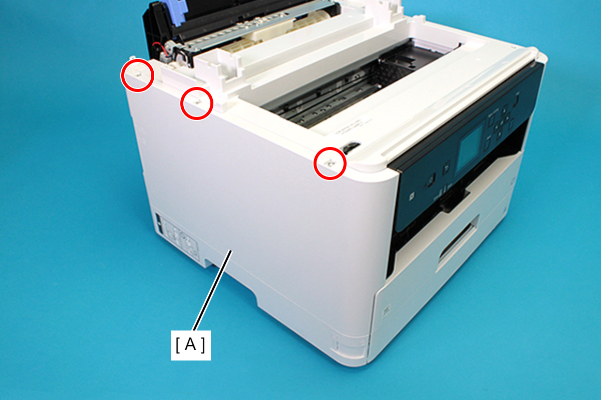
- Remove the Printer Cover (A) upward.
- Remove the seven screws and remove the Housing Top (A).
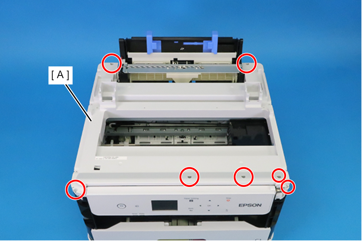
- : C.B.P-TITE-SCREW-3x10-F.ZN-3C
Remove the two Bind Screw2.5 x 20 (w/washer).
- Remove the Plate (A).
- Remove the two screws, and remove the Guide Cover (A) in the direction of the arrow.
- : C.C.P-TITE-SCREW-3x12-F.ZN-3C
 : C.B.P-TITE-SCREW-3x10-F.ZN-3C
- Remove the two screws securing the Cable Guide (A).
- : C.B.P-TITE-SCREW-3x10-F.ZN-3C
Check Point / チェックポイントWhen removing the screws, if the screwdriver interferes with the ADF/SCN Unit, use a stubby screwdriver.
- Peel off the CRCM FFC (B) from the CRCM FFC Sheet (A).
- Peel off the double-sided tape at two locations and then remove the CRCM FFC Sheet (A).
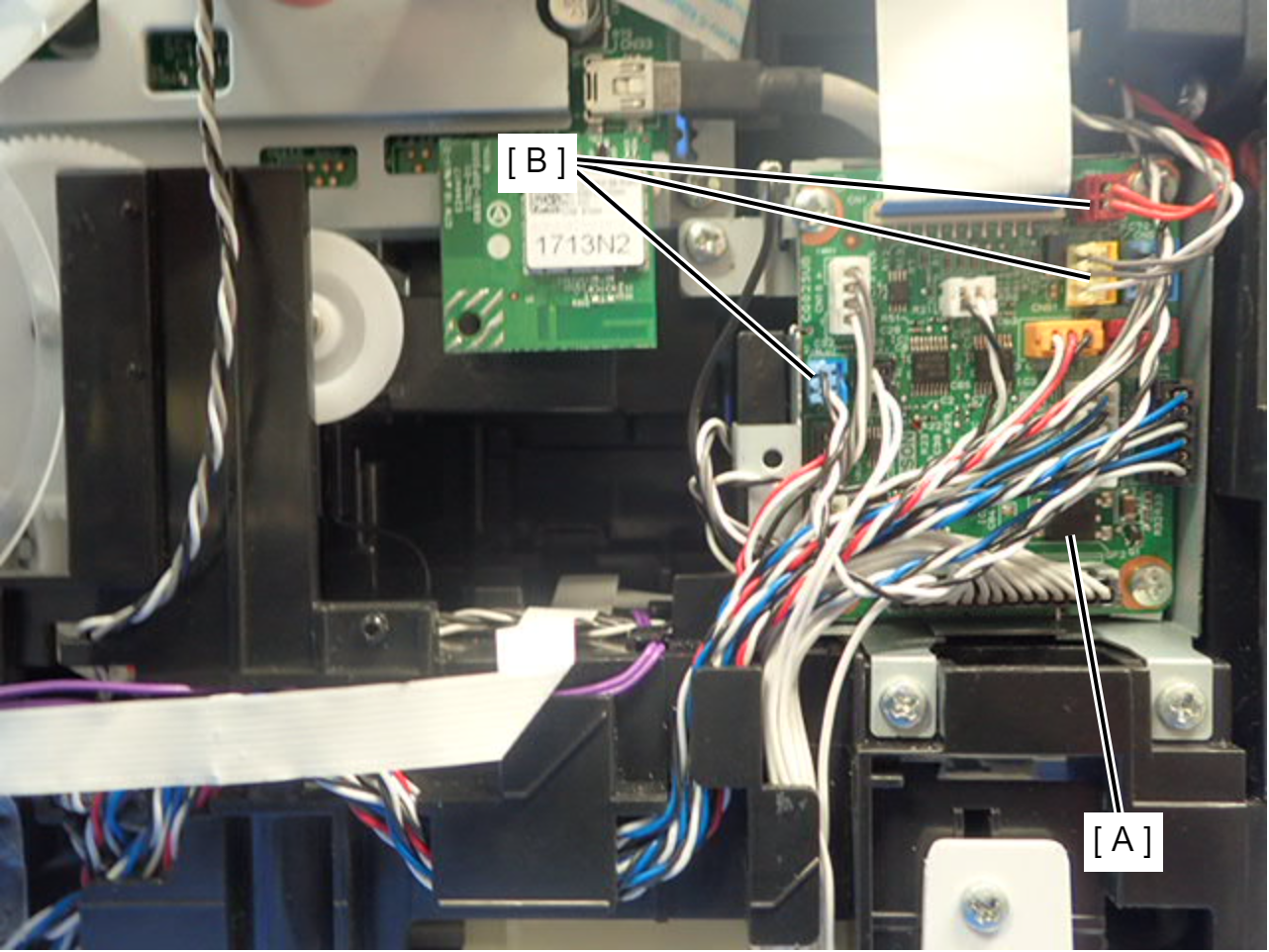
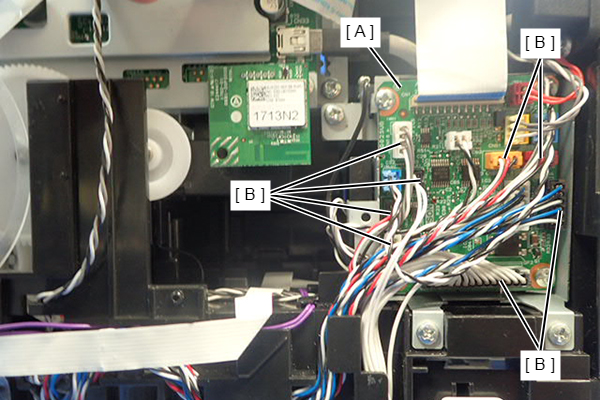
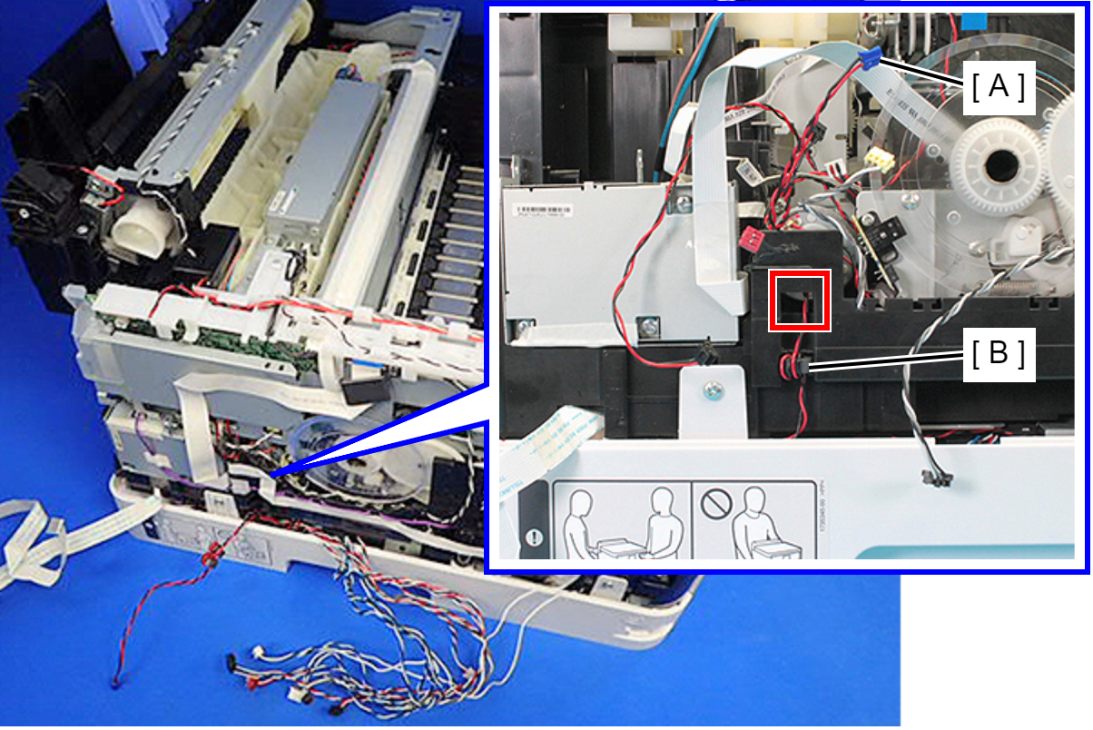
- Disconnect the cables (B) from the connector (CN20, CN51, CN56) of the Relay Board (A).
- Remove the acetate tape (A), and release the cable (B) from the two guides.
- Disconnect the two cables (B) from the connectors (CN74, CN80) of the Main Board (A).
- Remove the two screws, and release the ground wire (A) from the slit to remove it.
- : C.B.S-TITE-SCREW-3x6-F.ZN-3C
Assembly / 組み立てAttach the ground wire with the terminal (A) oriented as shown below.
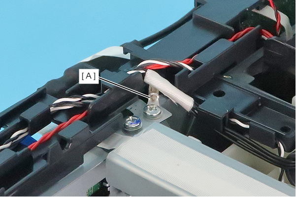
- Move the Cable Guide as shown below.
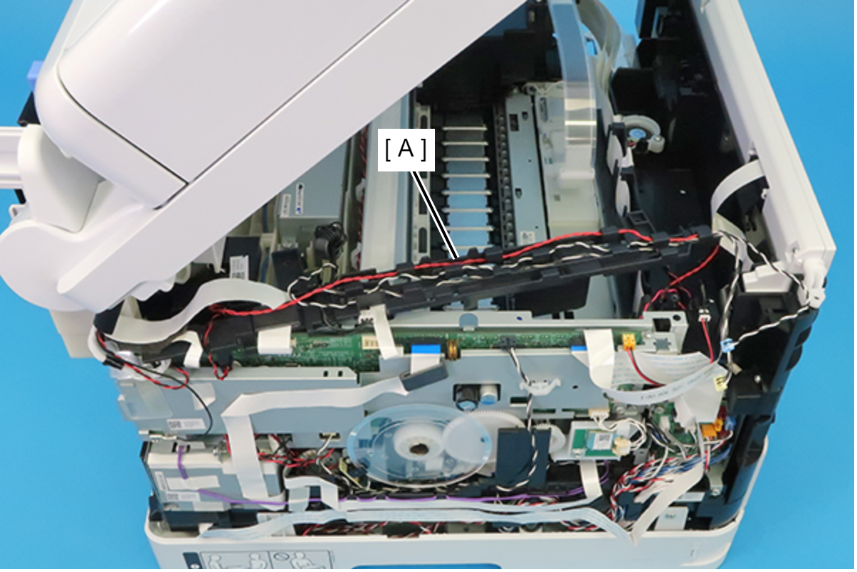
- Peel off the double-sided tape at 5 locations on the CRCM FFC (A).
- Disconnect the cables from the connectors (CN2, CN10, CN11, CN12, CN22, CN30, CN54, CN55) on the Relay Board (A).
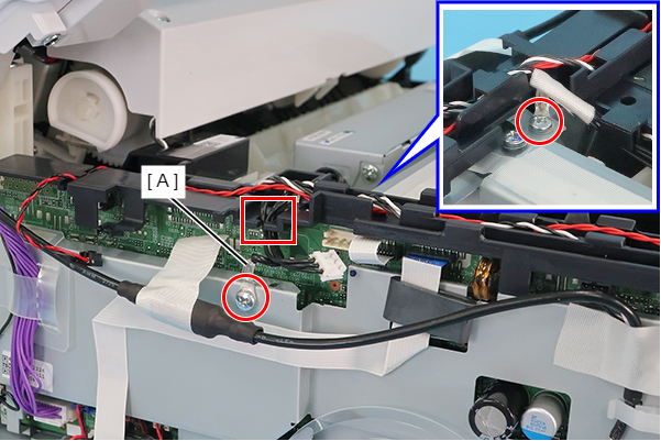
Release the cables from the five tabs on the Frame Base.
 Assembly / 組み立て
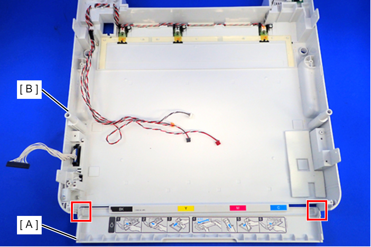
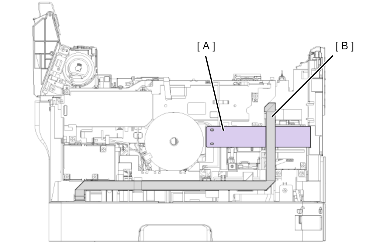
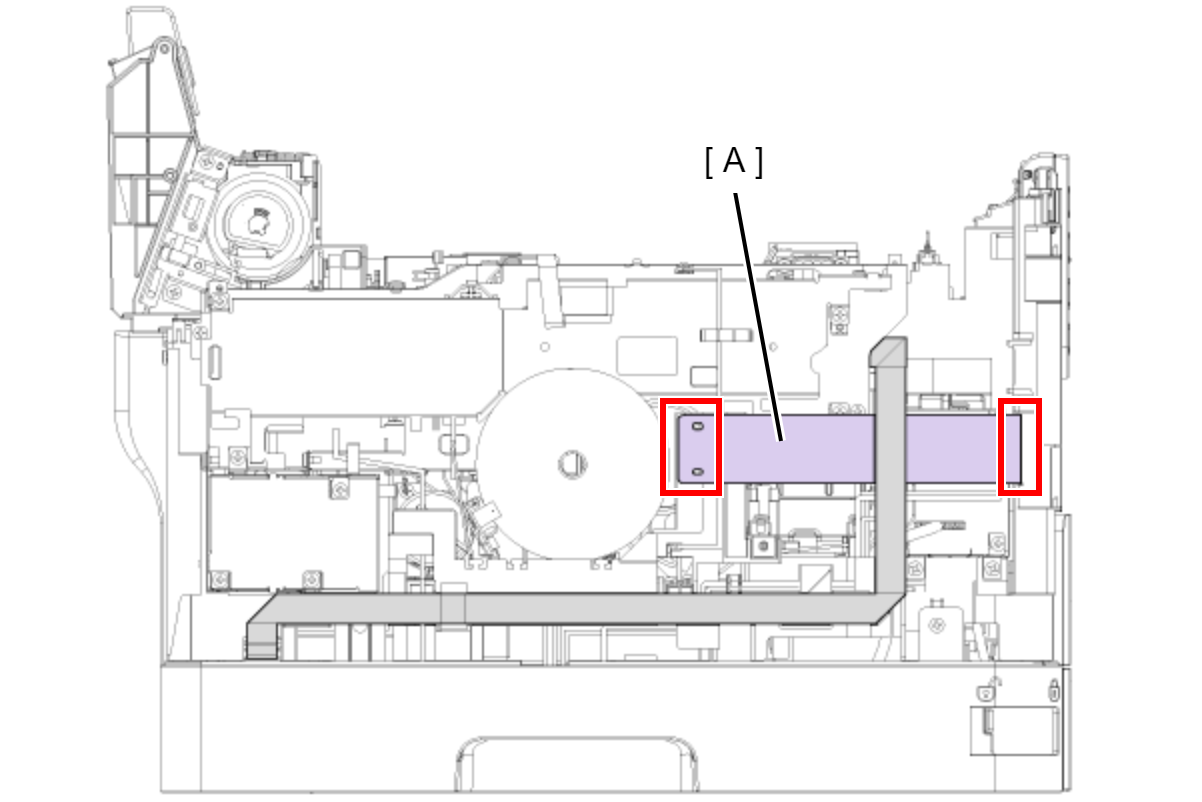
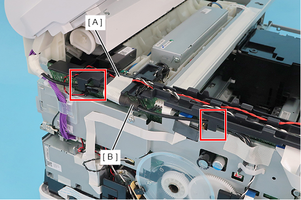
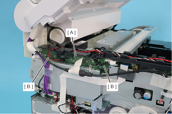
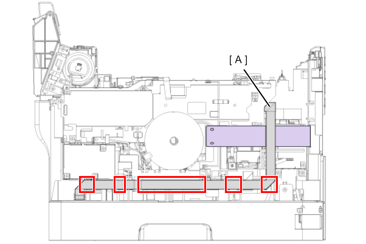
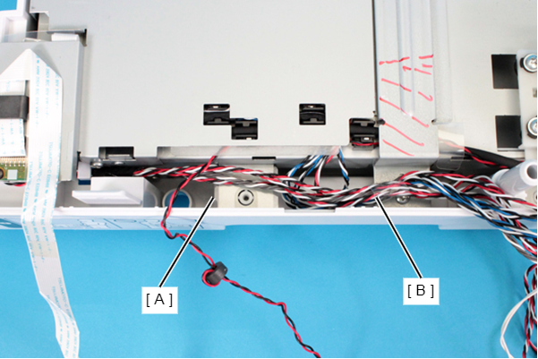
Cables to be routed to A and B in the figure below are as follows.
A
- Ink End Sensor (Bk) (CN30)
- Ink Leak Sensor 1 (CN11)
- Ink Leak Sensor 2 (CN12)
- Ink Leak Sensor 3 (CN54)
- Ink Leak Sensor 4 (CN55)
- Temperature and Humidity Sensor(CN10)
B
- Drawer Connector (CN2)
- Cover Open Sensor (CN22)
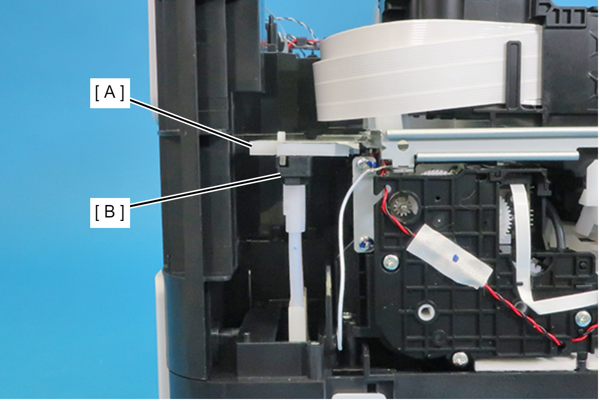
Disconnect the FFCs (A) from the connectors (CN67, CN66, CN68) on the Main Board.
- Disconnect the CRCM FFC (A) from the connector (CN8) on the Main Board.
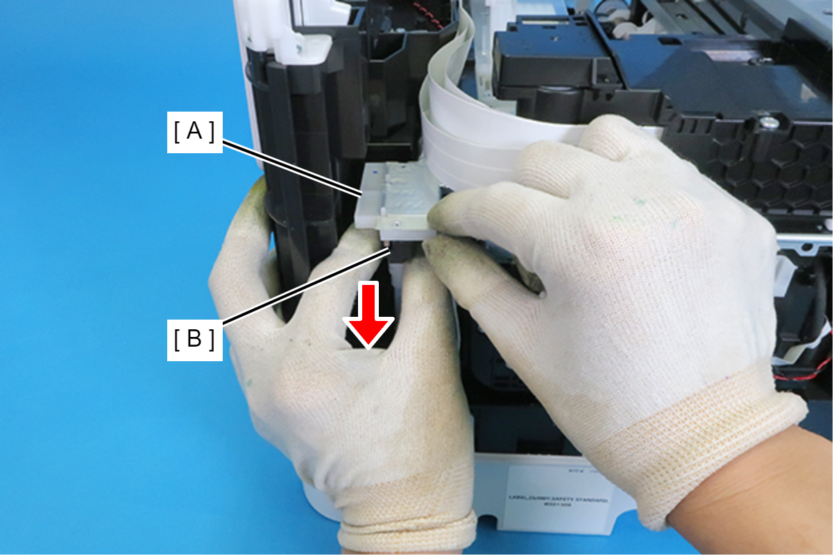
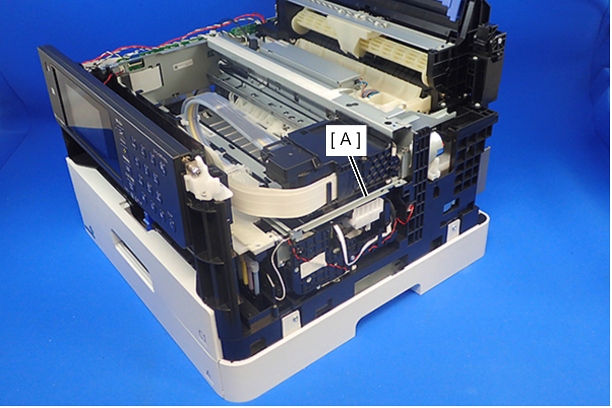
- Remove the Decompression Pump Cable (A) from the connector (CN77) on the Main Board.
- Pull the Decompression Pump Cable (A) out from the hole of the Frame Base, and remove the ferrite core (B).
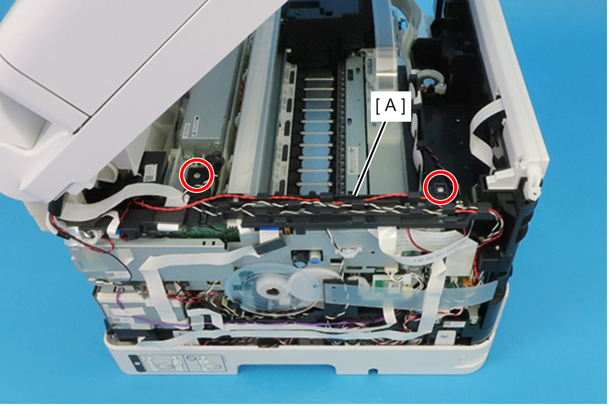
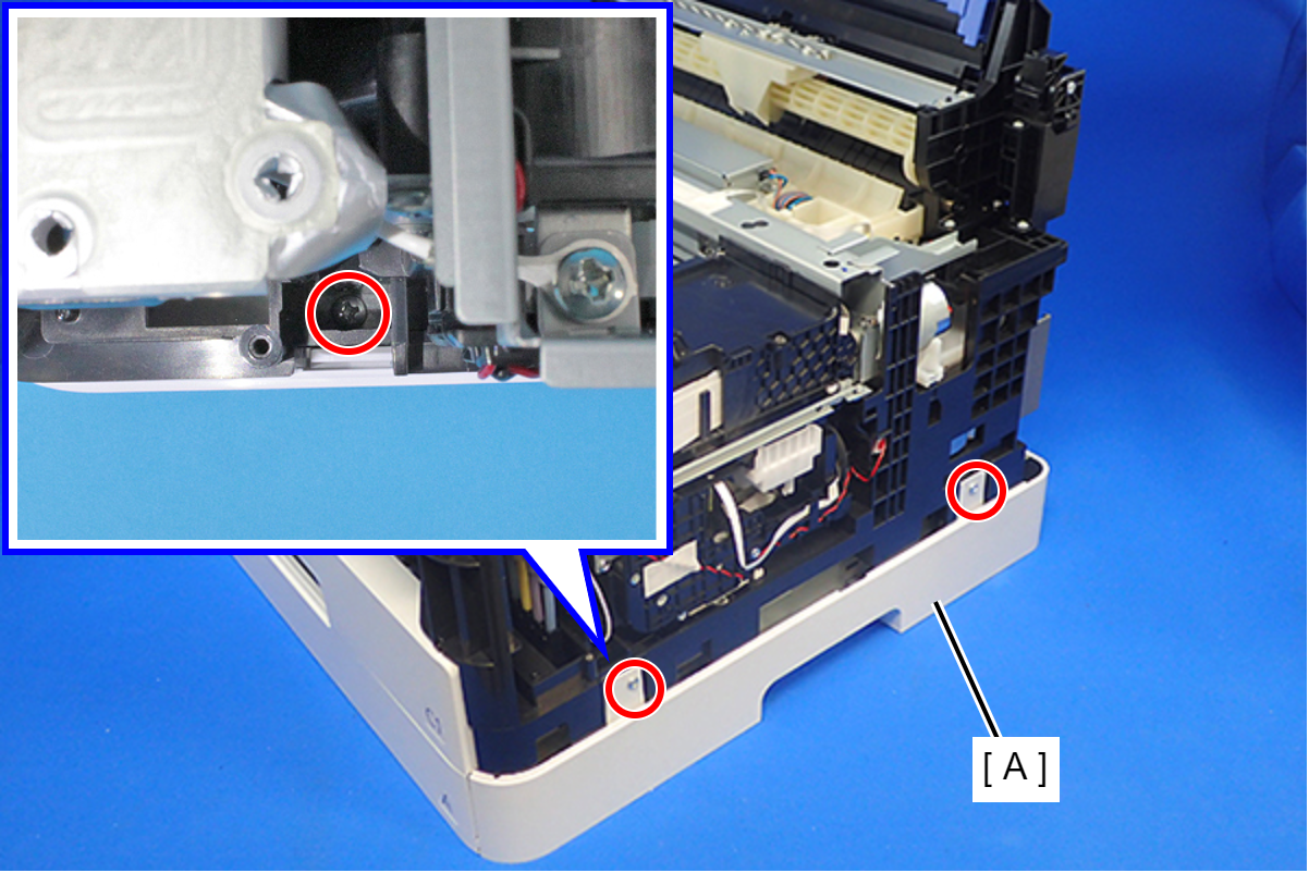
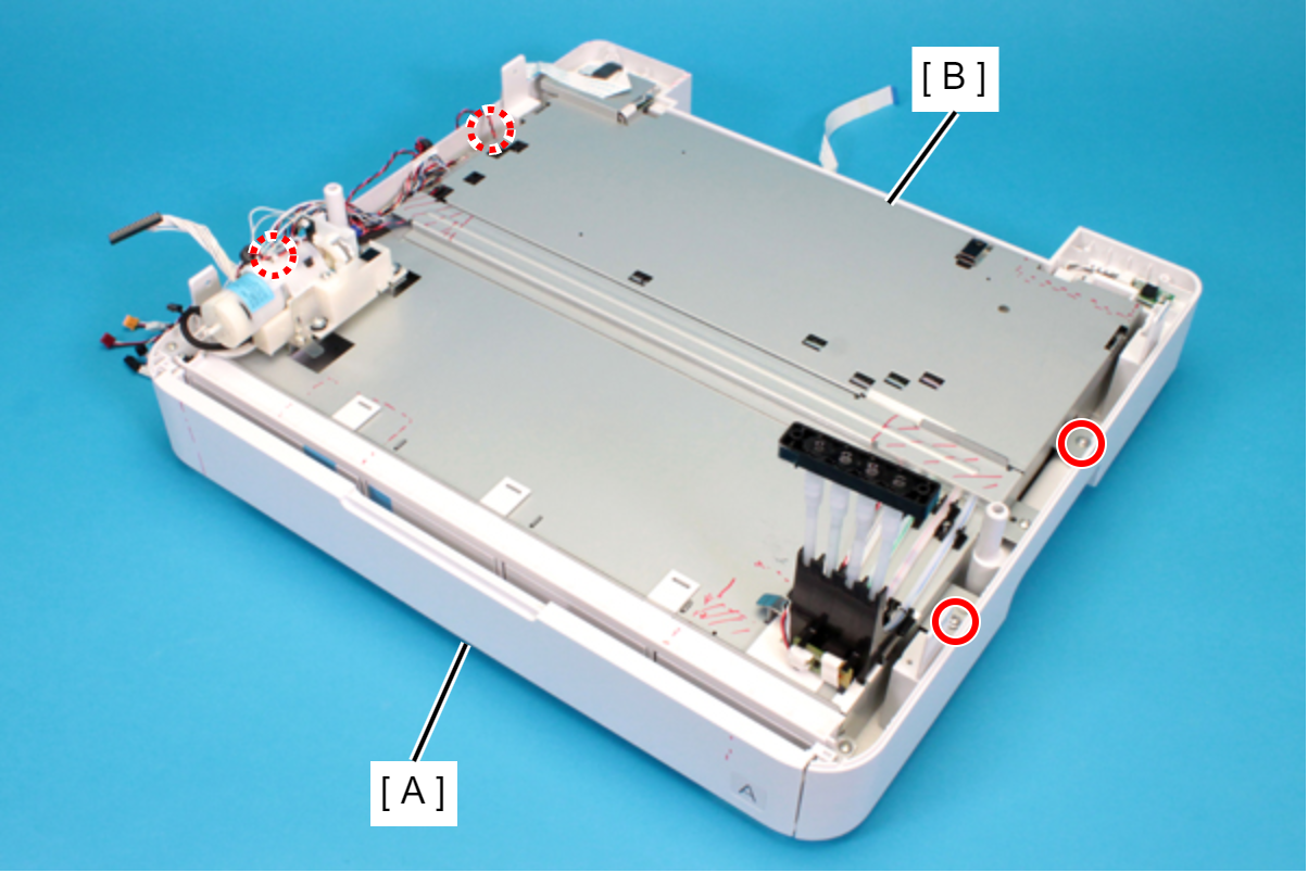
- Remove the three screws that secure the RIPS Unit (A).
- : C.B.P-TITE-SCREW-3x10-F.ZN-3C
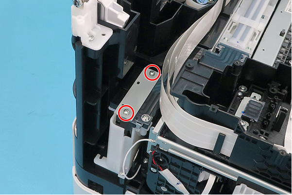
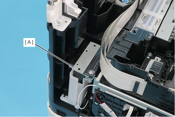
Remove the two screws that secure the RIPS Unit (A).
- : C.B.P-TITE-SCREW-3x10-F.ZN-3C
Remove the three screws that secure the RIPS Unit (A).
- : C.B.P-TITE-SCREW-3x10-F.ZN-3C
 Caution / 注意
In the following steps, ink may spill from the Ink Supply Tube. Prepare waste cloths or similar in advance.
While holding up the Ink Supply Tube (A), pull down the Joint (B) to remove it.
 Assembly / 組み立て
When the Joint (B) has been installed, check that there is no gap between the Ink Supply Tube (A) and the Joint (B).
 Caution / 注意
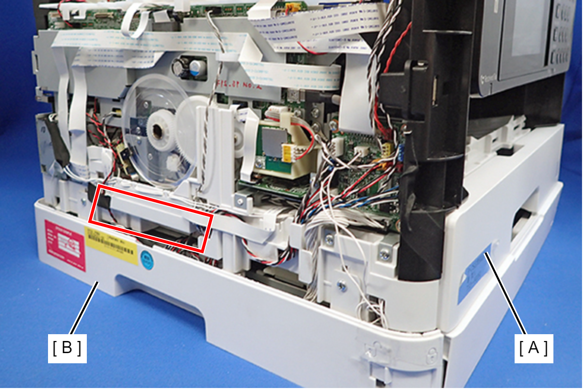
- In order to prevent injuries from the edge of the metal frame (A), use long sleeves when lifting the printer.
Lift carefully so as not to touch the PF scale (A) on the left side of the main body. If you touch the PF scale, clean it with a clean cloth.
- In order to prevent injuries from the edge of the metal frame (A), use long sleeves when lifting the printer.
Holding the location in the figure, lift the printer (A), and separate the printer (A) and the RIPS Unit (B).
Right side
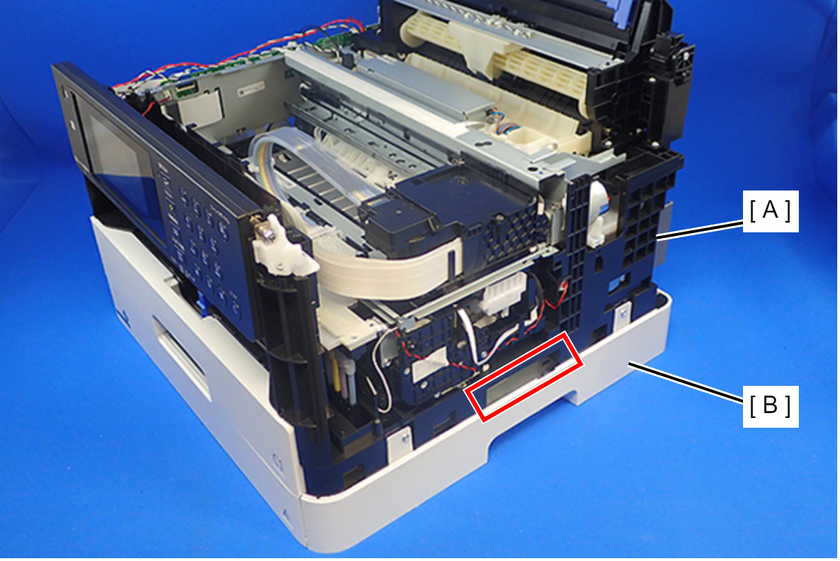
- Left side
Assembly / 組み立てDuring disassembly and reassembly, ink leakage may occur from the tube and joint section being misaligned.
Check that the tube rib (A) and the joint section are perpendicular and secure as in the figure below.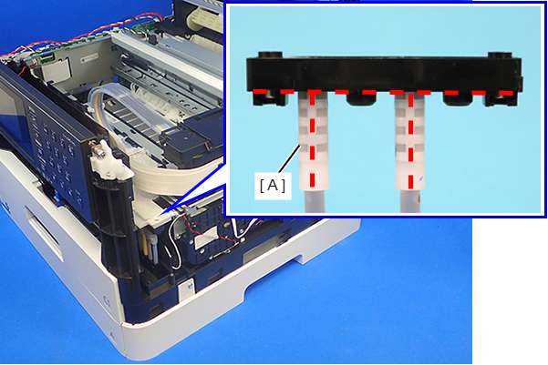
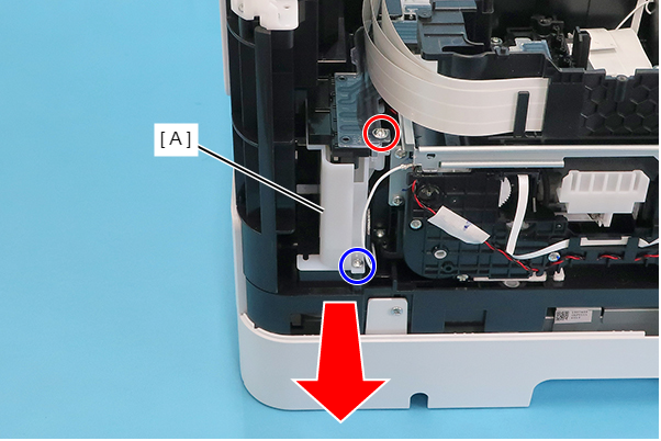
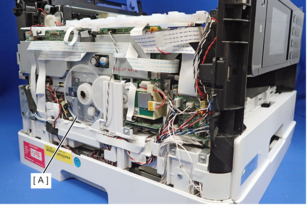
- Remove the screw and then remove the Front Cover Open Sensor (A).
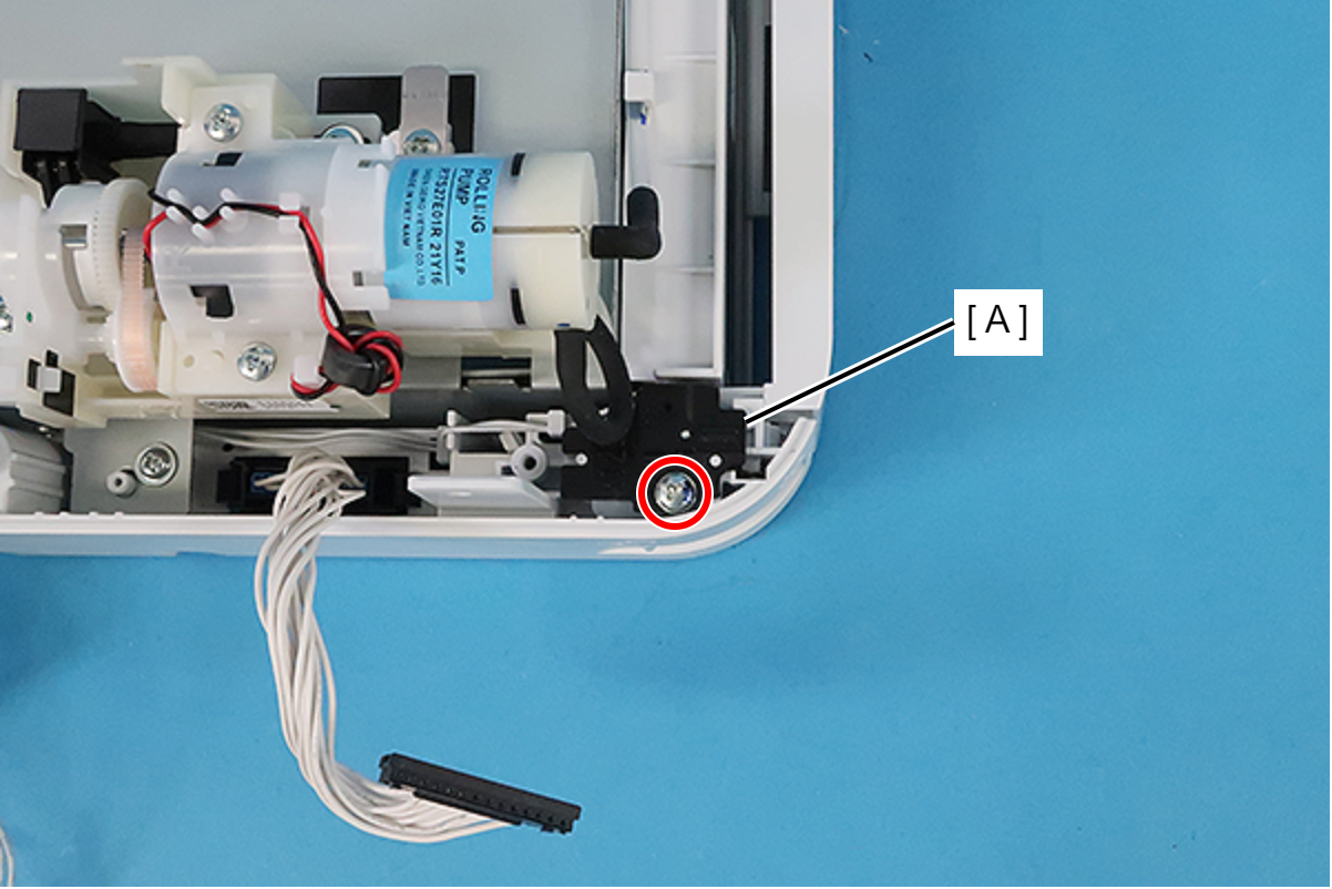
- : C.B.P-TITE.P2.SCREW-3x12-F.ZN-3C
- Remove the four screws, then remove the Ink Supply Unit (B) from the Ink Supply Housing (A).
- : C.C.P-TITE-SCREW-3x8-F.ZN-3C
Assembly / 組み立てRoute the cables (B) of the Ink Supply Unit (A) on the frame of the Ink Supply Unit (A).
- While slightly warping the RIPS Front Cover (A), pull out its two shafts from the two holes to remove the RIPS Front Cover (A) from the RIPS Unit Lower (B).