Lift Motor
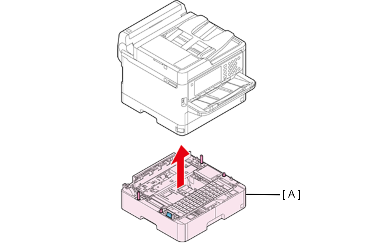
Lift the printer, then remove the Optional Paper Cassette (A).
 Assembly / 組み立て
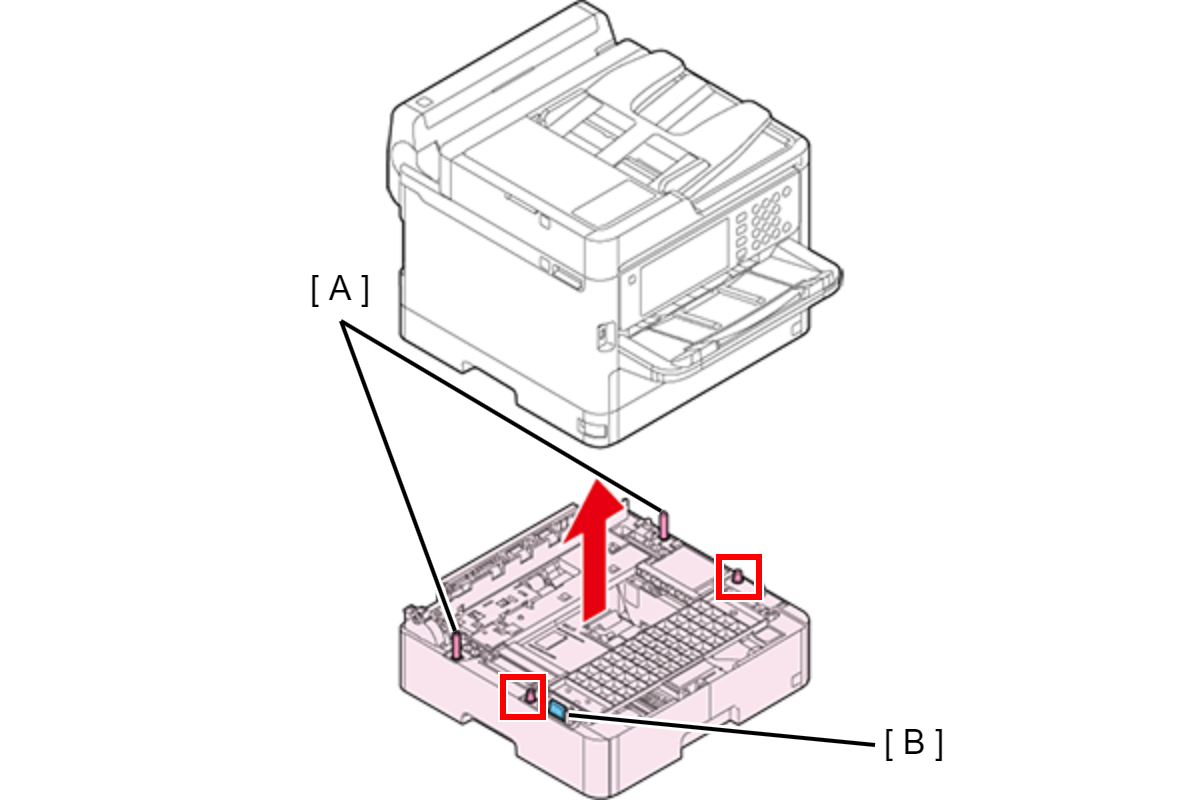
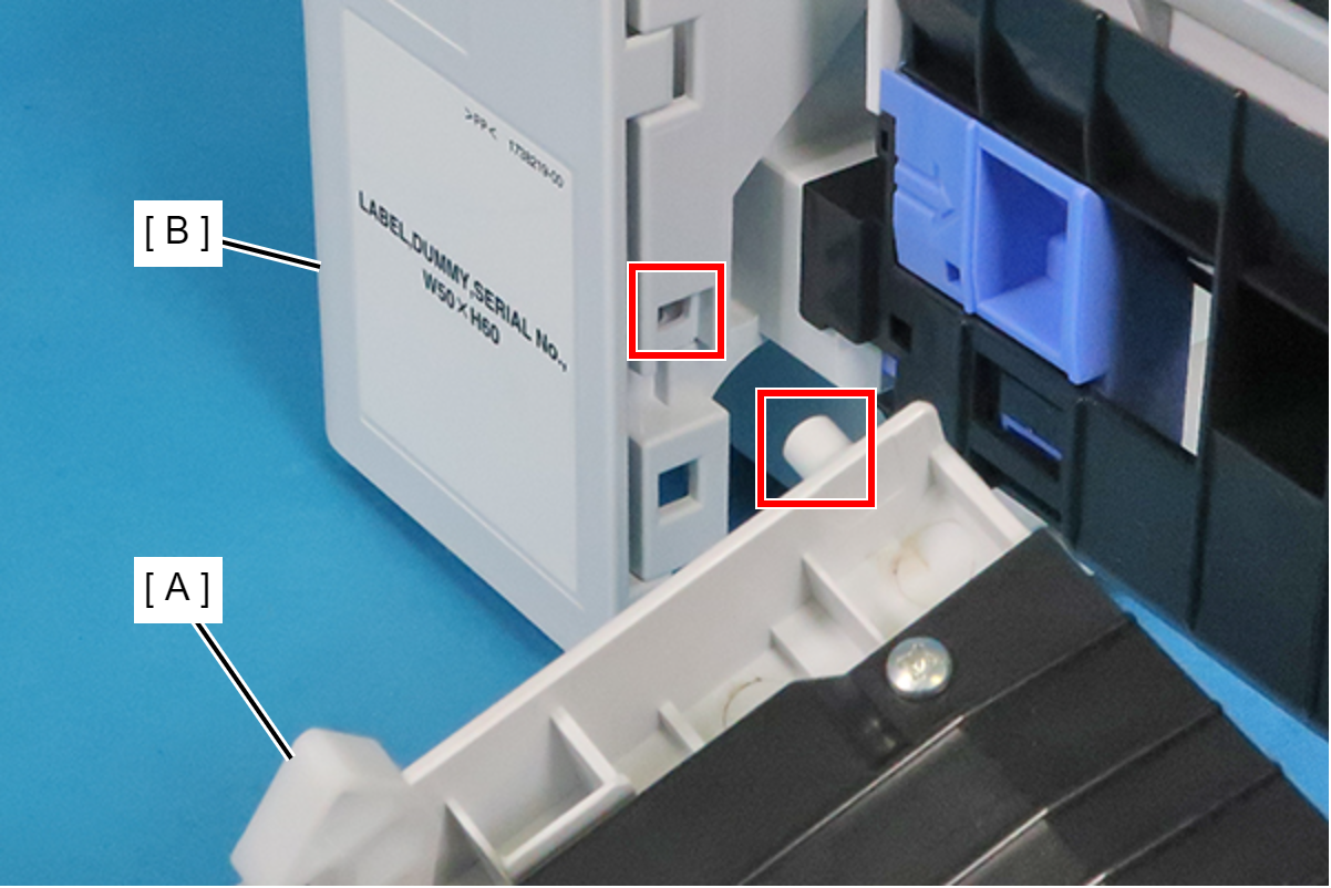
When attaching the Optional Paper Cassette, be sure to align the two positioning pins (A) and the two dowels so as to avoid damage to the Drawer Connector (B).
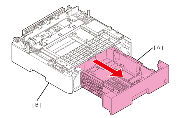
- Pull out the Paper Cassette 2nd Assy (A), then remove the Paper Cassette 2nd Assy (A) from the Optional Paper Cassette (B).
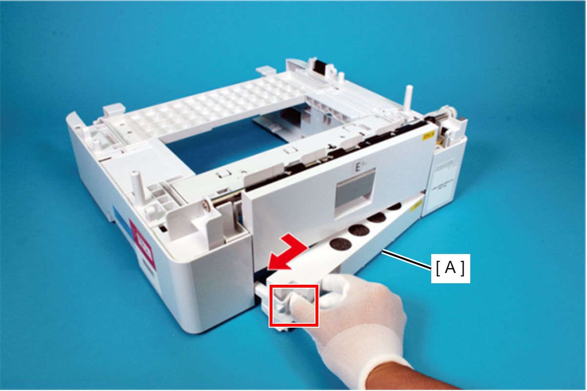
Pick the tab, and remove the Rear Lower Cover Assy (A) in the direction of the arrow.
 Assembly / 組み立て
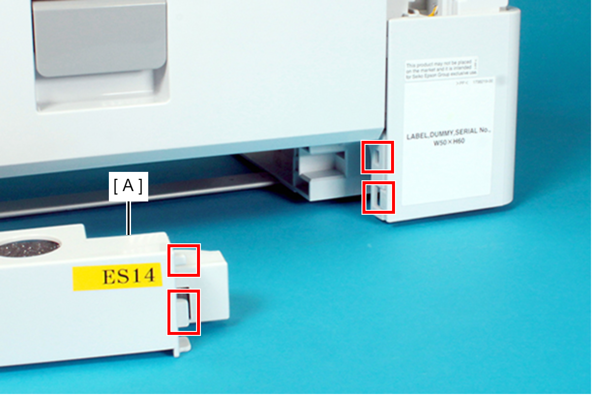
When installing the Rear Lower Cover Assy (A), attach the two ribs of the Rear Lower Cover Assy (A) to the holes of the frame.
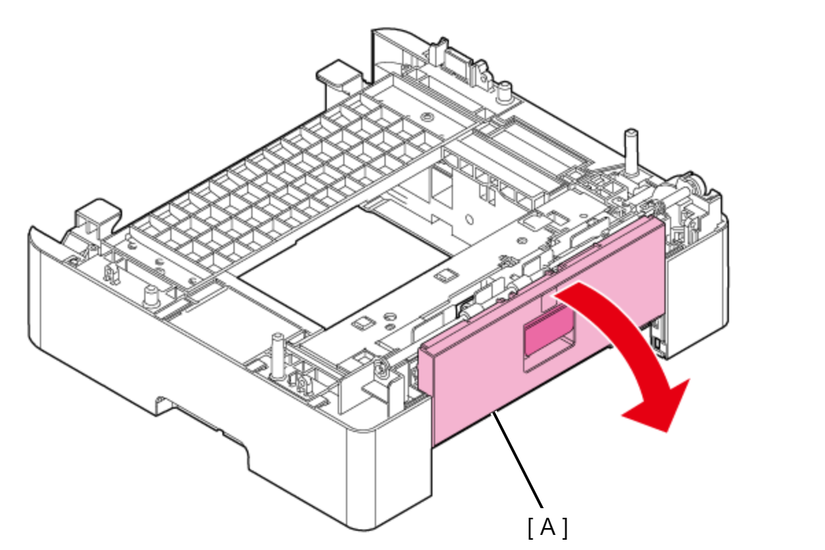
- Open the Optional Paper Cassette Rear Cover (A).
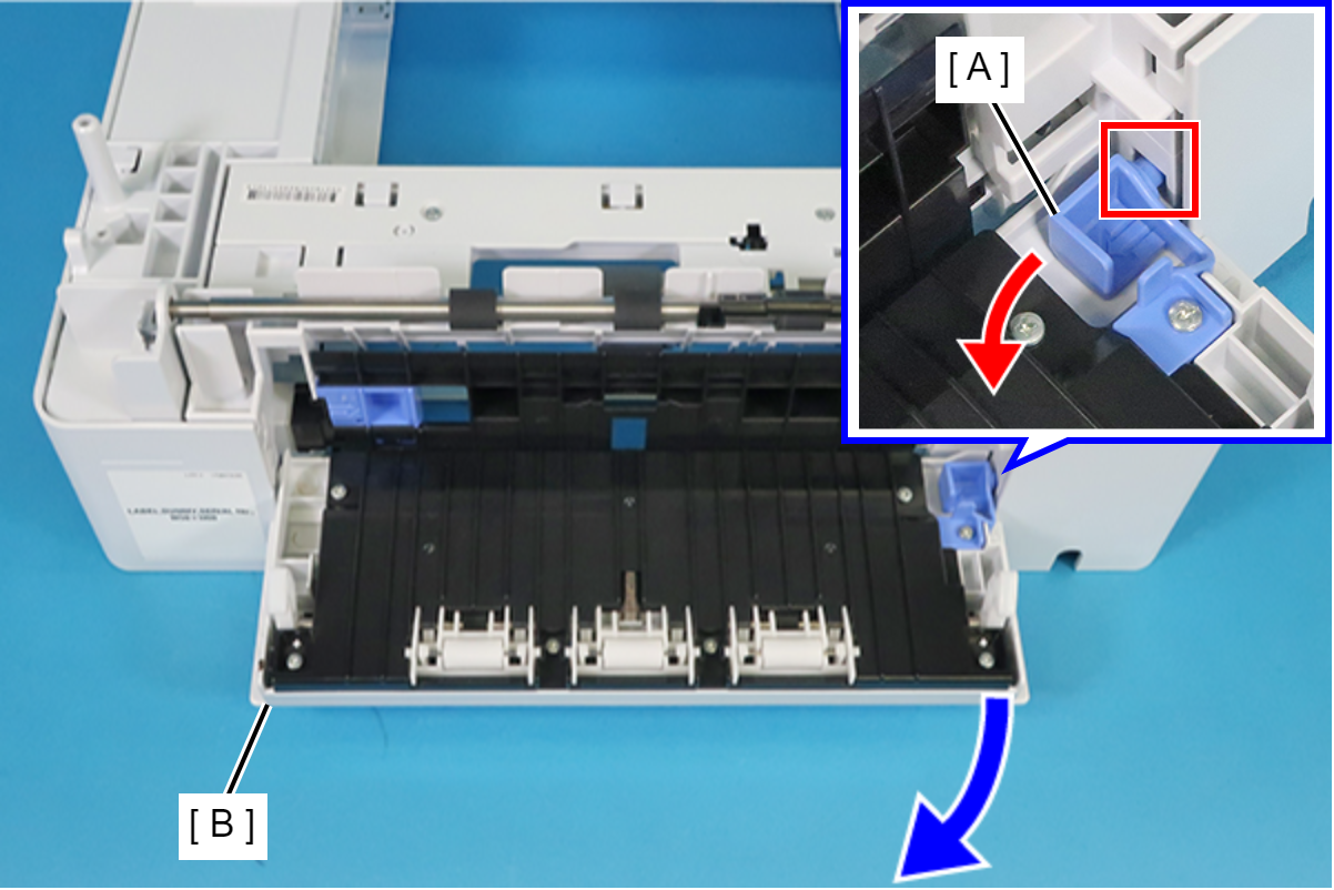
Push the Optional Paper Cassette Rear Cover Slider (A) in the direction of the red arrow to disengage the dowel from the hole in the frame, and then remove the Rear Housing (B) by pulling it in the direction of the blue arrow.
 Assembly / 組み立て
When installing the Rear Housing (A), first insert the dowel shown below into the hole in the frame (B).
- Remove the three screws securing the Optional Paper Cassette Left Cover (A).
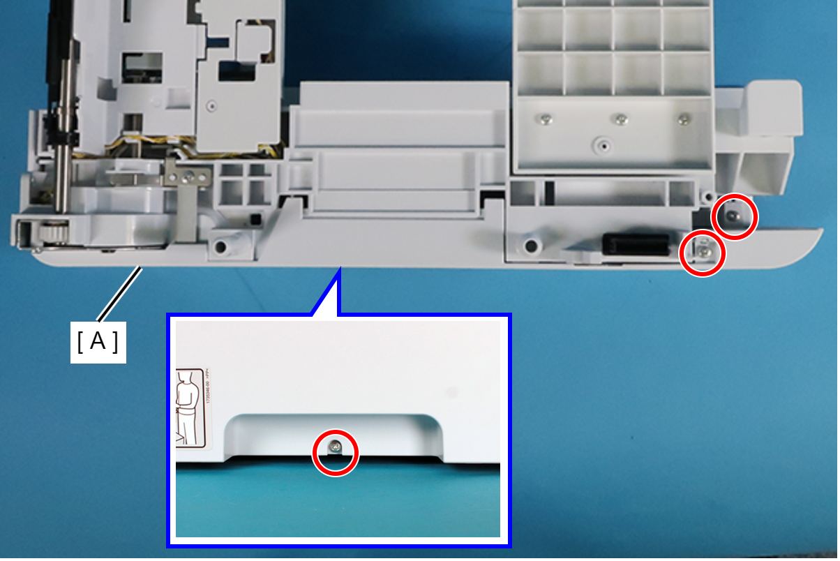
 : C.B.P-TITE-SCREW-3x10-F.ZN-3C
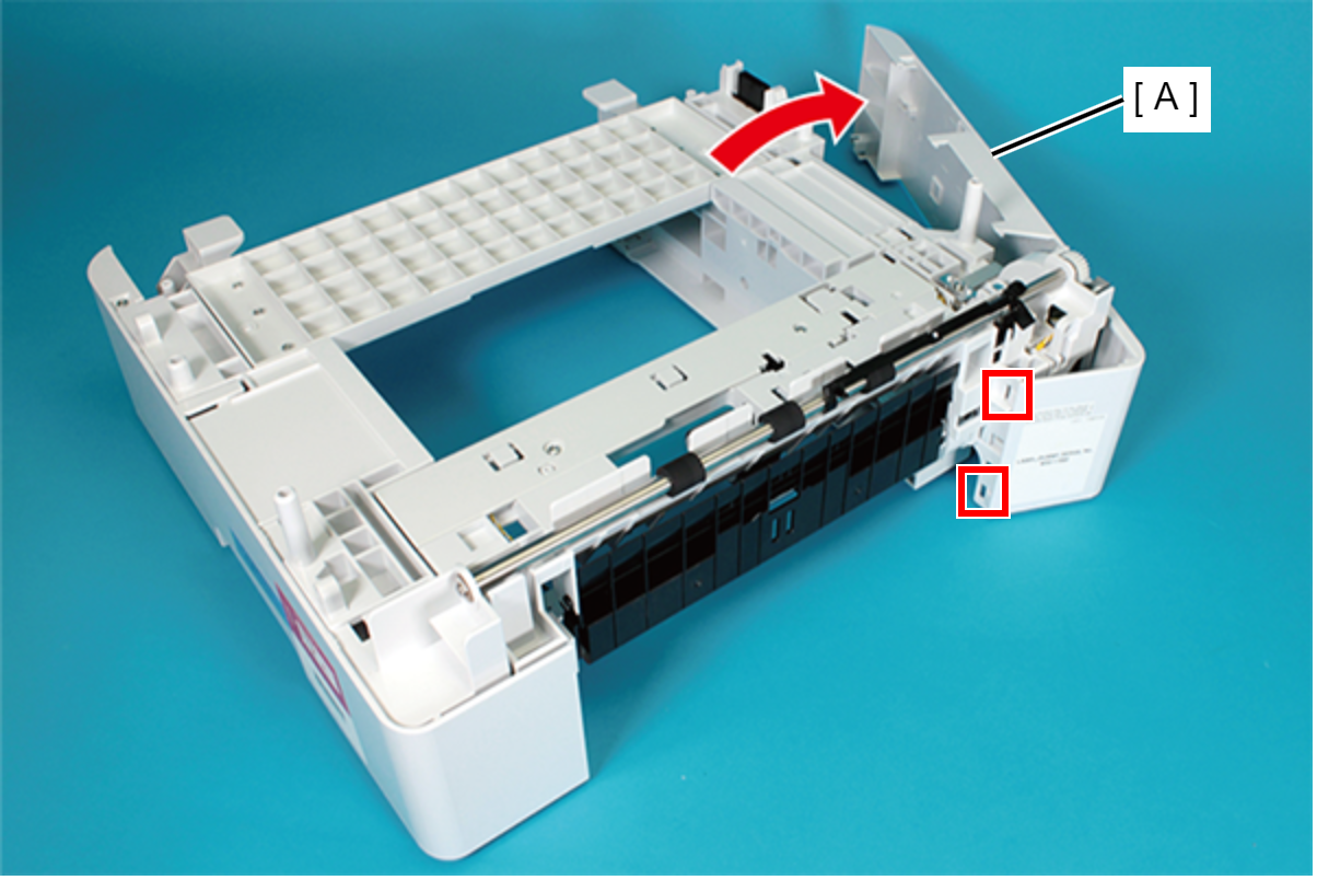
- Disengage the two hooks of the Optional Paper Cassette Left Cover (A) and release it from the dowels on the frame.
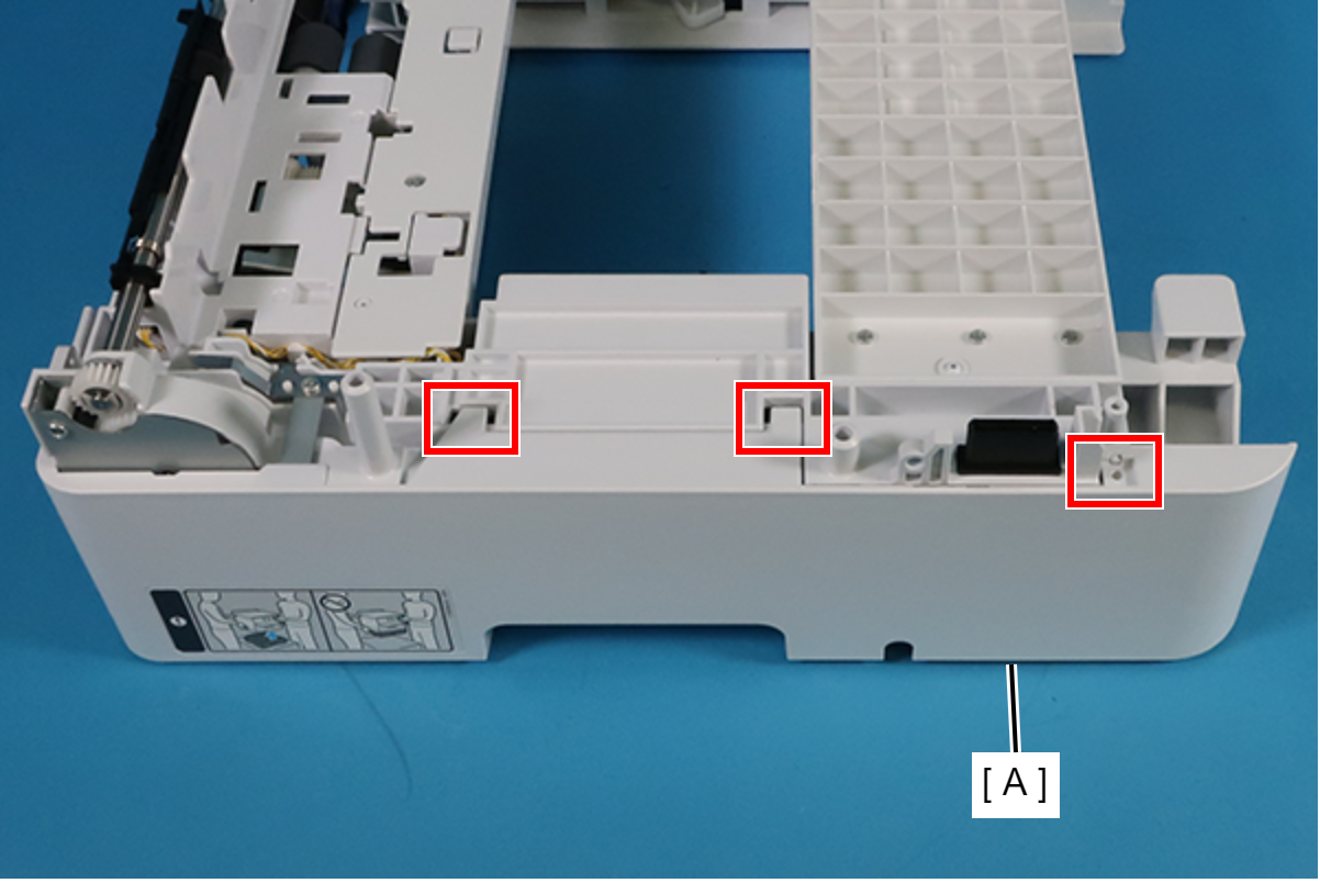
Rotate in the direction of the arrow, remove the two hooks on the rear side, and then remove the Optional Paper Cassette Left Cover (A).
- Remove all connectors connected to the Optional Paper Cassette Main Board Assy (A).
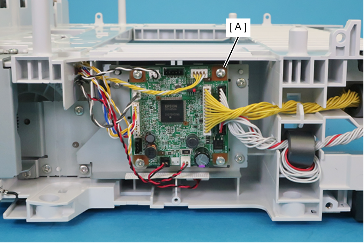
- Remove the four screws, and then remove the Optional Paper Cassette Main Board Assy (A).
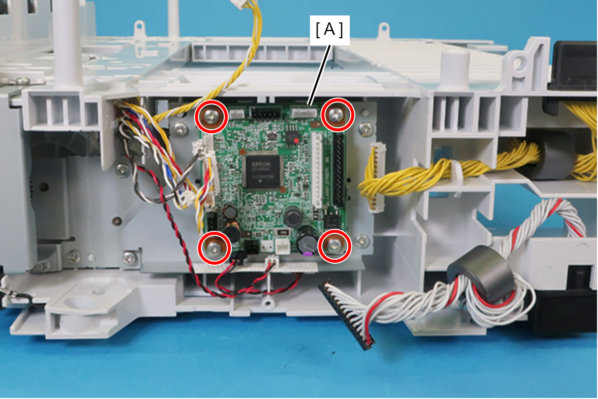
- : C.B.S-TITE-SCREW-3x6-F.ZN-3C
Assembly / 組み立てRoute the cables connected to the Optional Paper Cassette Main Board Assy with reference to the figure below.
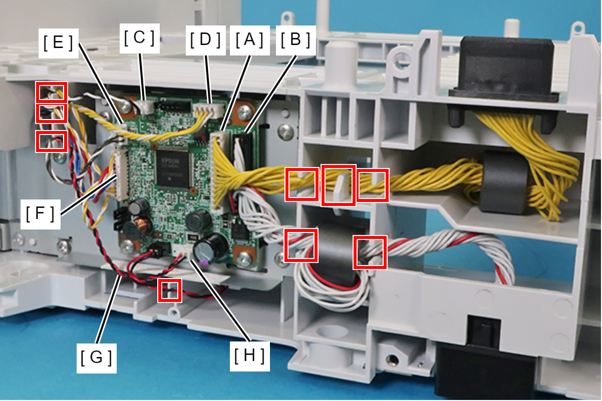
Symbol Cable A Drawer Connector (female) Cable (CN1) B Drawer Connector Cable (CN2) C Jam Cover Detection Sensor Cable (CN5) D ASF Encoder Cable (CN6) E Lift Phase Sensor Cable (CN6) F Sensors Cable (CN7) G Lift Motor Cable (CN12) H ASF Motor Cable (CN13)
- The Feed Sensor, Cassette Detection Sensor, Cassette Detection Sensor, and Hopper Position Sensor are connected to CN7 (F).
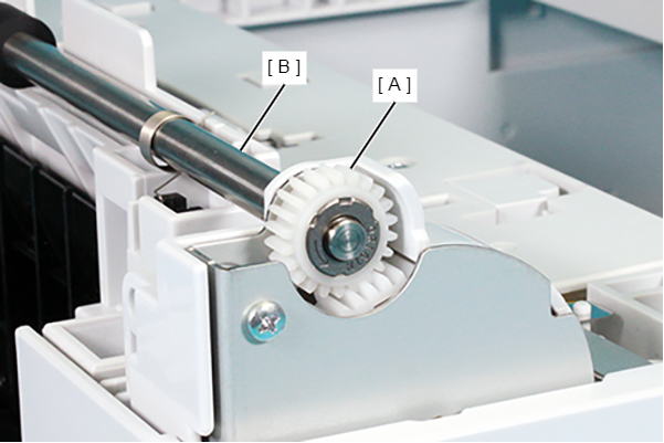
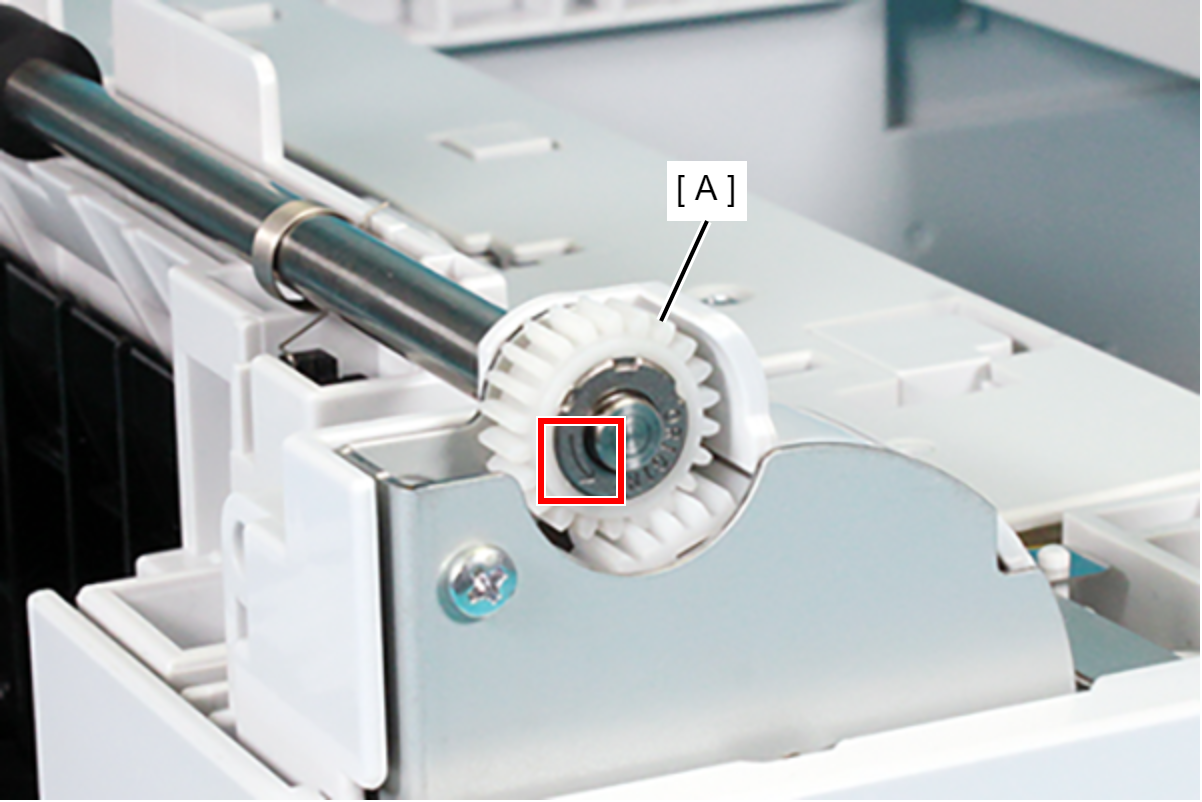
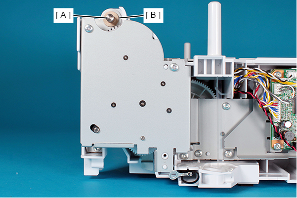
- Remove the E-ring (plastic) (B) from the left side of the Vertical Feed Roller (A).
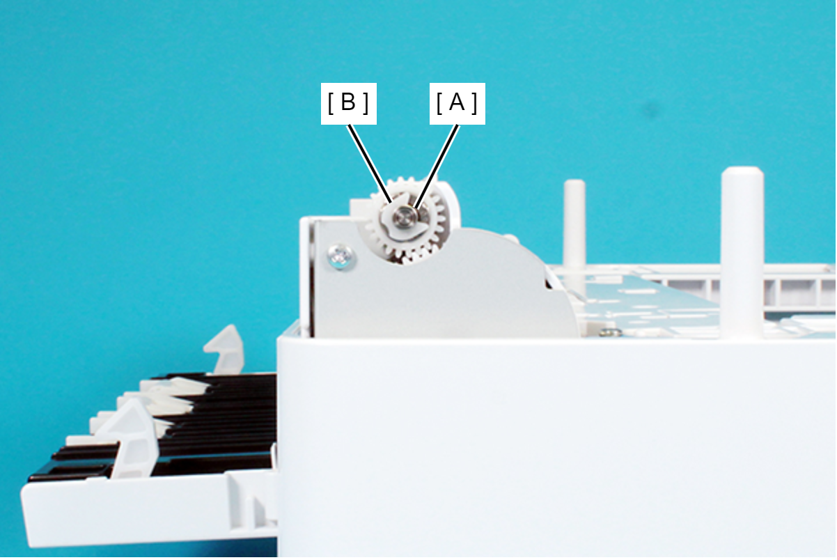
Remove the One-way Gear (A) from the Vertical Feed Roller (B).
 Assembly / 組み立て
When attaching the One-way Gear (A), make sure the arrow mark is facing outside as shown in the figure below.
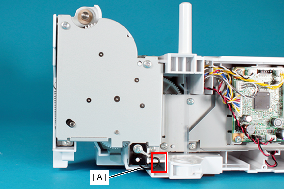
- Remove the screw, and then remove the grounding cable (A) and the Grounding Sheet (B).
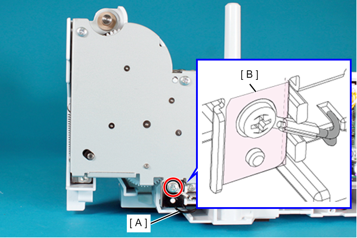
- : C.B.P-TITE-SCREW-3x10-F.ZN-3C
Assembly / 組み立てRoute the grounding cable (A) in the groove of the frame shown in the figure below.
- Remove the screw and then remove the Upper Grounding Plate (A).
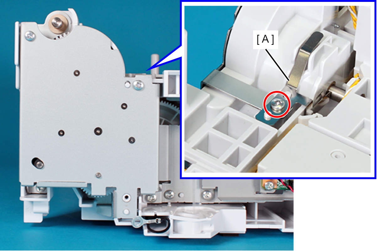
- : C.B.P-TITE-SCREW-3x10-F.ZN-3C
Assembly / 組み立て- When attaching the Upper Grounding Plate (A), be sure to align the positioning hole of the Upper Grounding Plate (A) and the dowel of the frame.
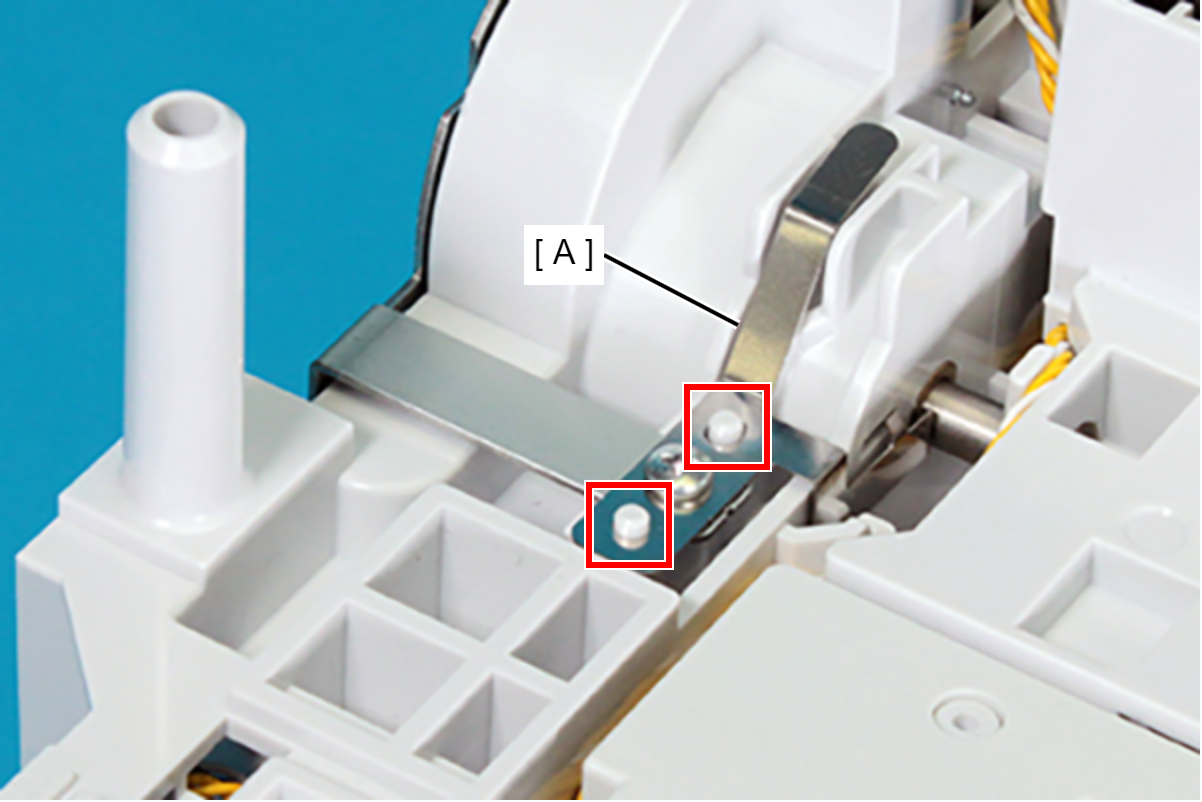
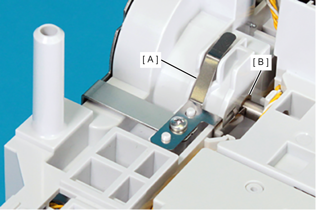
- Make sure the tip of the Upper Grounding Plate (A) is in contact with the bearing (B).
- Remove the bearing (B) from the Vertical Feed Roller (A).
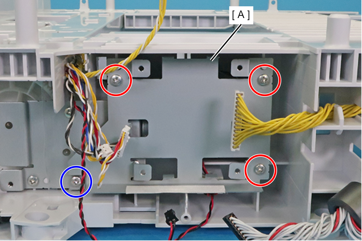
- Remove the four screws and remove the Hopper Drive Assy (A).
- : C.B.S-TITE-SCREW-3x6-F.ZN-3C
 : C.B.P-TITE-SCREW-3x10-F.ZN-3C
Assembly / 組み立てWhen attaching the Hopper Drive Assy (A), align the three dowels with the three holes in the Hopper Drive Assy (A).

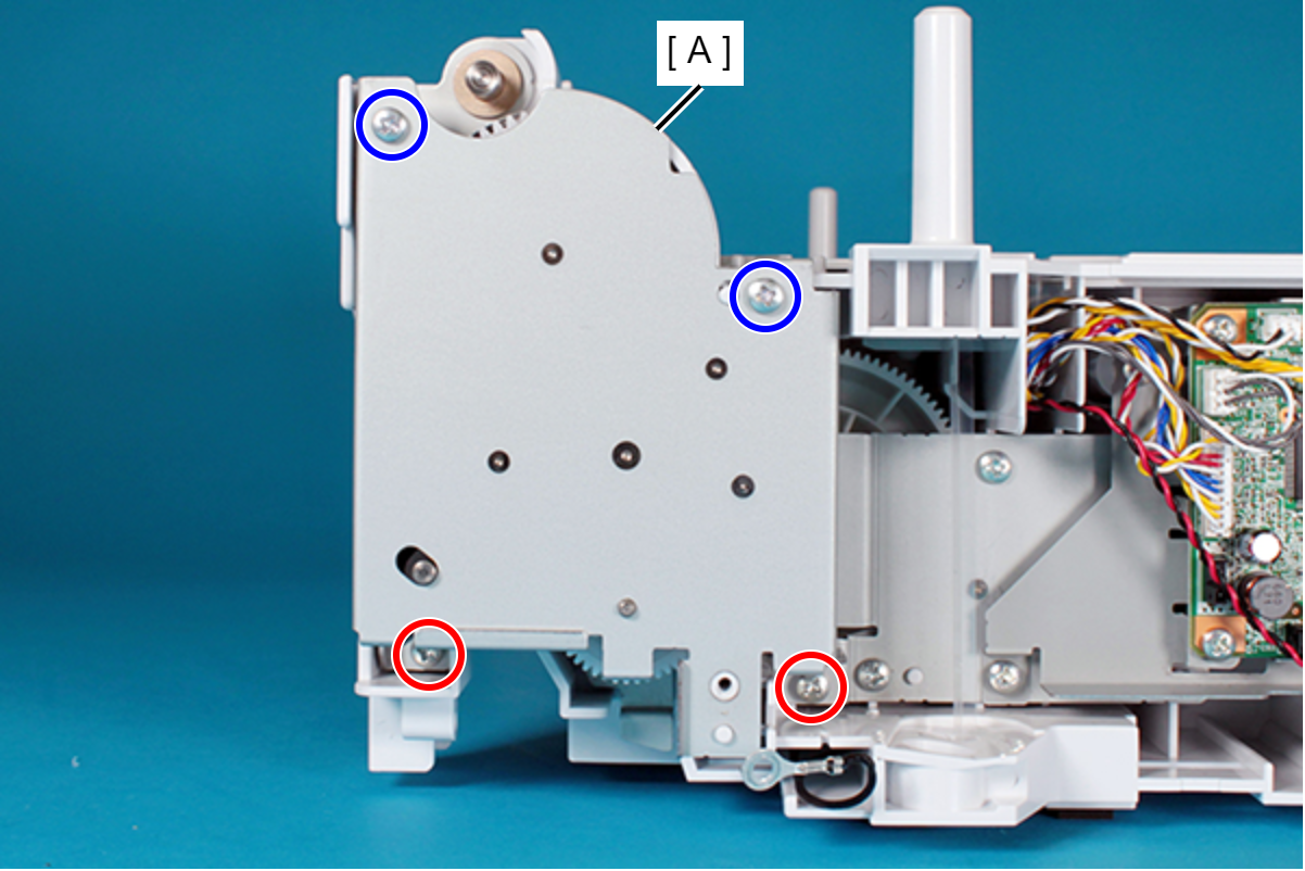
- Remove the four screws and then remove the plate (A).
- : C.B.P-TITE-SCREW-3x10-F.ZN-3C
- : C.B.S-TITE-SCREW-3x6-F.ZN-3C
- Remove the four screws securing the Lift Motor Assy (A).
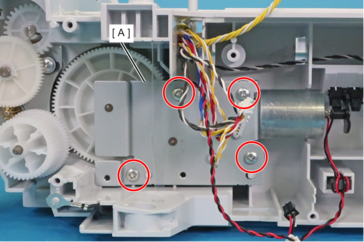
- : C.B.P-TITE-SCREW-3x10-F.ZN-3C
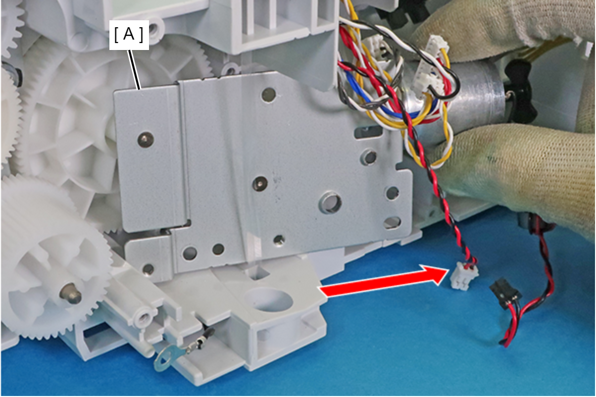
Pull the Lift Motor Assy (A) in the direction of the arrow to disengage it from the two gear holes and three dowels.
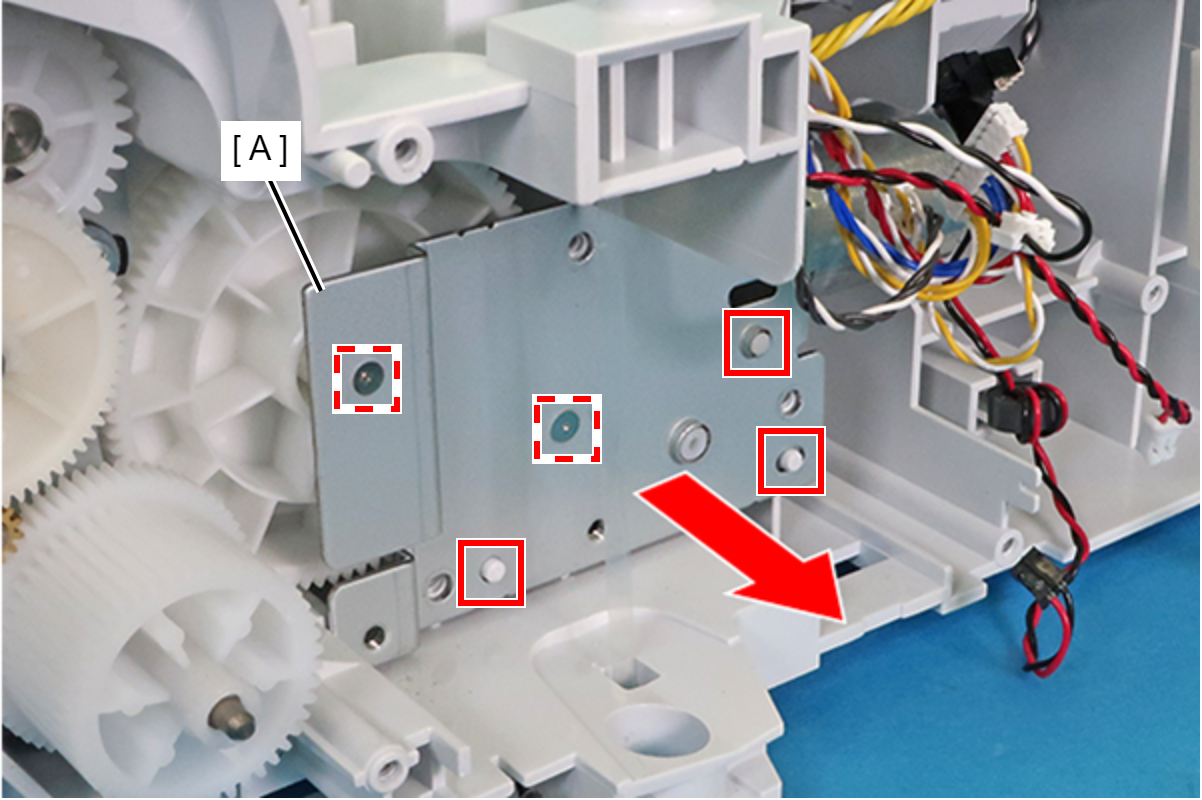
- Remove the Lift Motor Assy (A) in the direction of the arrow.
- Remove the two screws securing the Lift Motor (A).
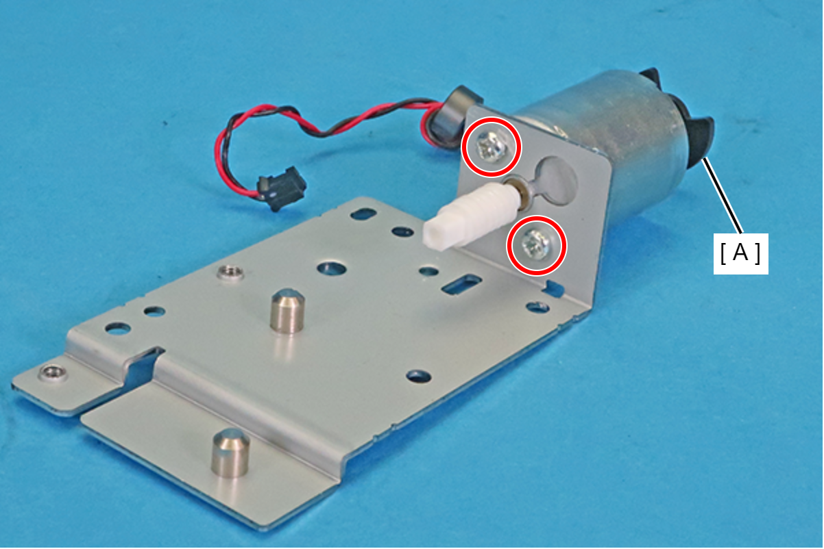
- : C.P.SCREW,3X3,F/ZN-3C
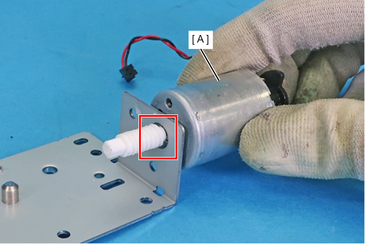
Assembly / 組み立てInstall the Lift Motor (A) with the side with the engraving in the position shown in the figure below.
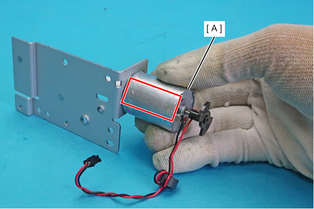
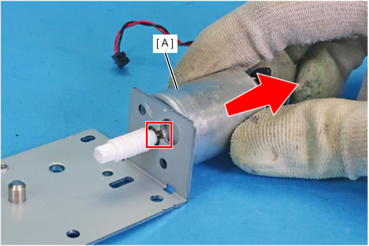
- Pull the Lift Motor (A) in the direction of the arrow to release its shaft from the hole in the plate.
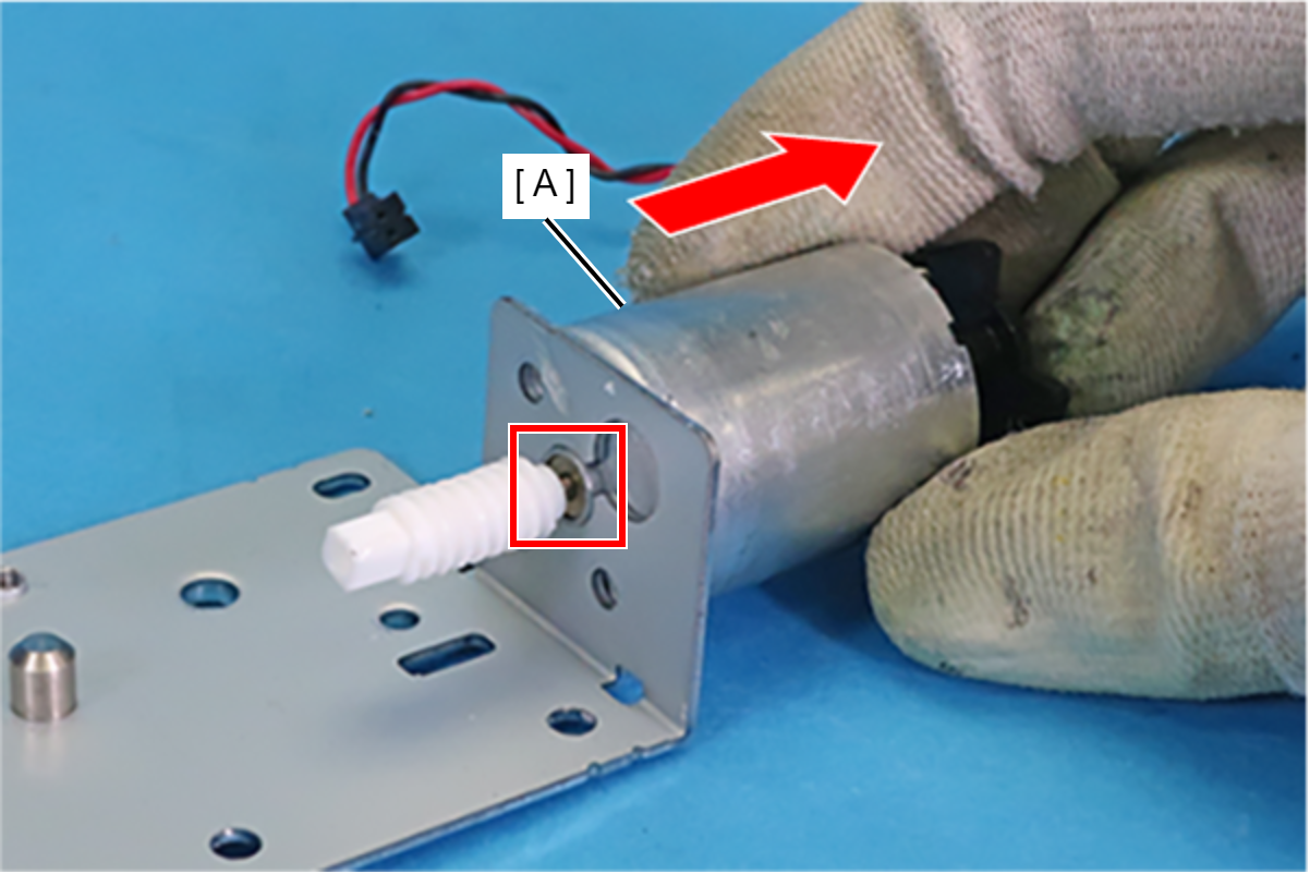
- Lift the Lift Motor (A) in the direction of the arrow to move its shaft to the upper hole in the plate.
- Remove the Lift Motor (A) by pulling its shaft out from the hole in the plate.