PG adjustment procedure
 Caution / 注意 Caution / 注意 |
When performing the PG adjustment, make sure of the following.
|
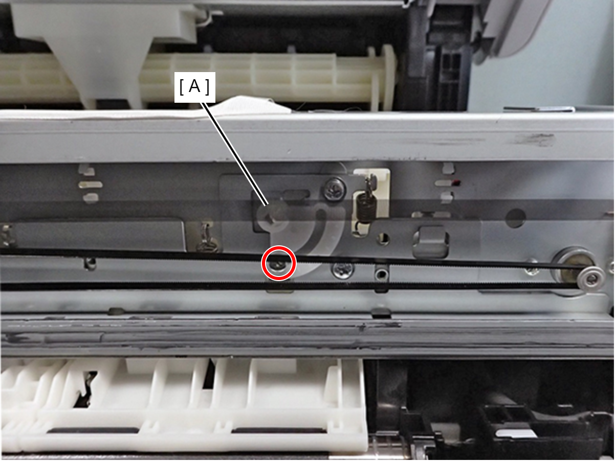
Loosen the fixing screw of the Left PG adjustment cam (A).
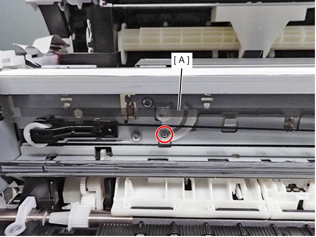
Loosen the fixing screw of the Right PG adjustment cam (A).
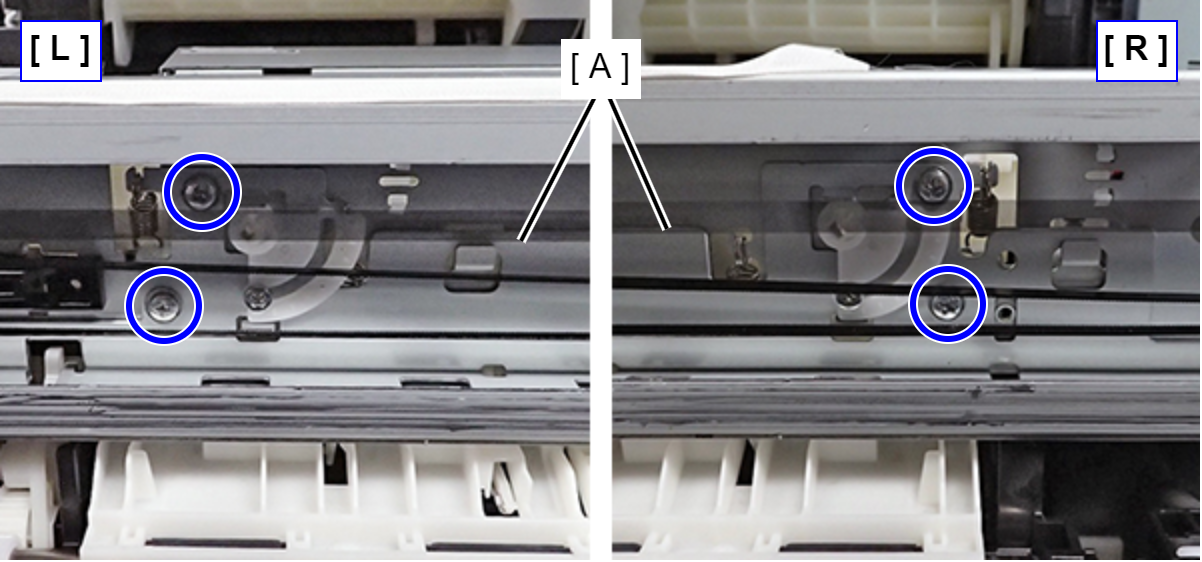
Loosen the four fixing screws of the CR guide frame (A).
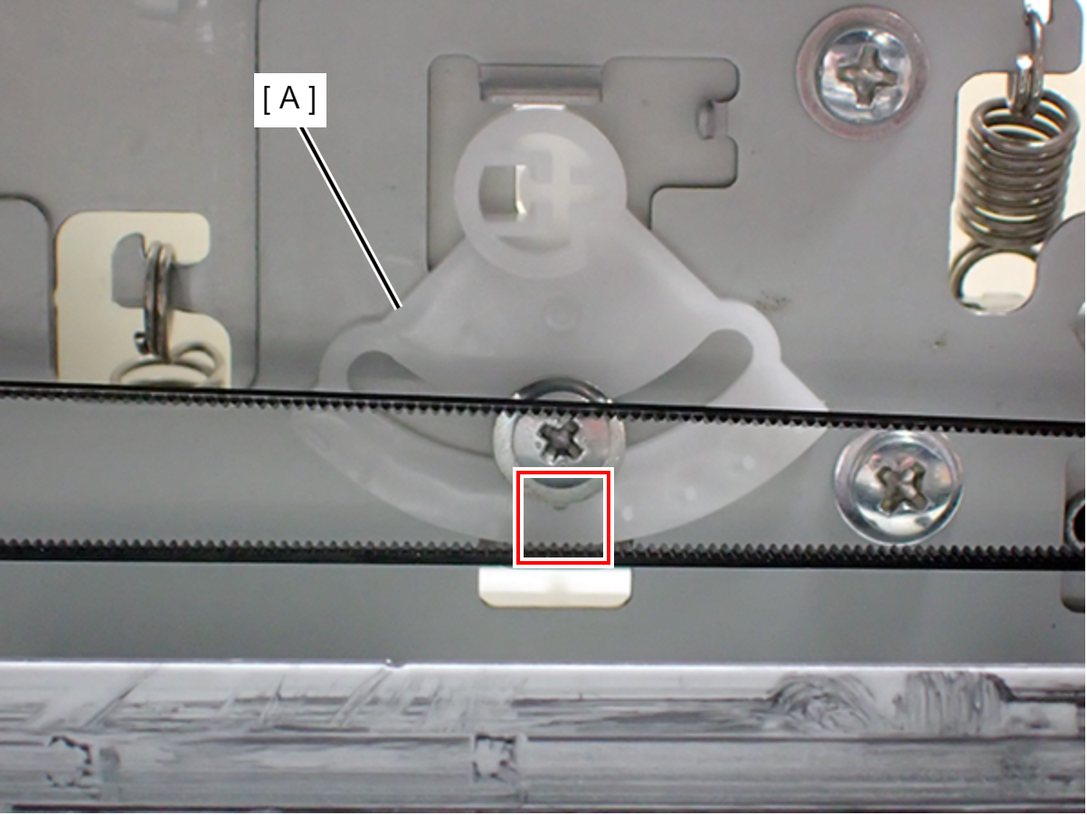
Align the Left PG adjustment cam and Right PG adjustment cam so that these both align with the origin point (with the hole in the middle of the cam (A) scale down).
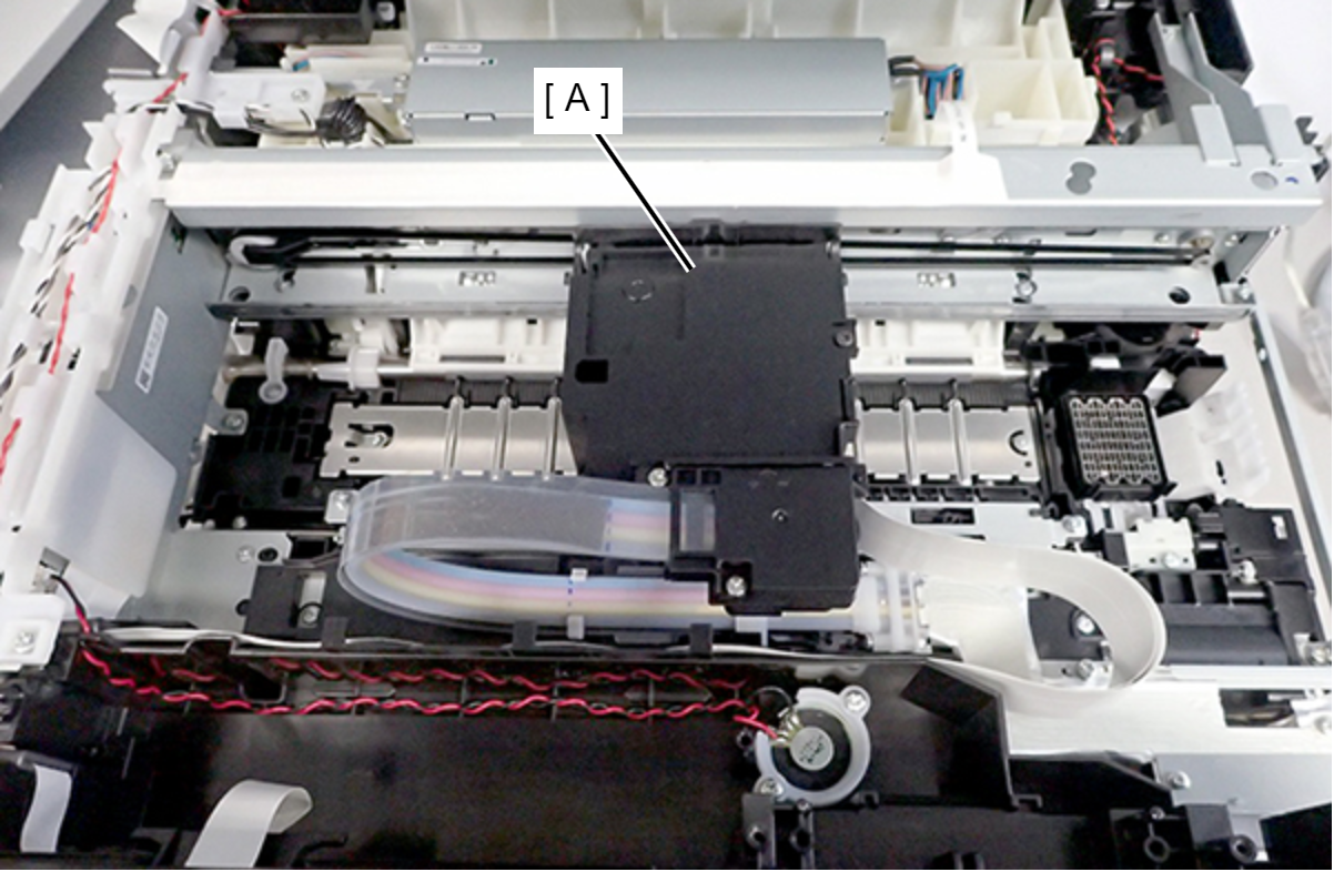
Move the CR Unit (A) to the center of the printer.
Place the thickness gauge (1.42 mm thickness gauge + 0.08 mm Teflon tape) at position (1) shown below.
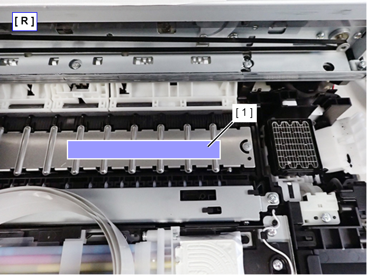
Move the CR unit to the thickness gauge and check whether or not the CR Unit touches the thickness gauge.
If does not touch the thickness gauge: Proceed to step 8.
If touches the thickness gauge: Perform the adjustment in the procedure below. If touches the thickness gauge even after adjustment, repeat the following steps until it does not touch the thickness gauge.
Move the CR unit to the center part of the printer.
Move the Right PG adjustment cam by one notch in the “+” direction.
Move the CR unit to the thickness gauge again and check whether or not the carriage touches the thickness gauge.
 Check Point / チェックポイント
- When moving the PG adjustment cam (A), align so that it comes to the position where the scale contacts the frame (B).
- The relationship between the PG adjustment cam (A) direction of movement and the PG is as follows.
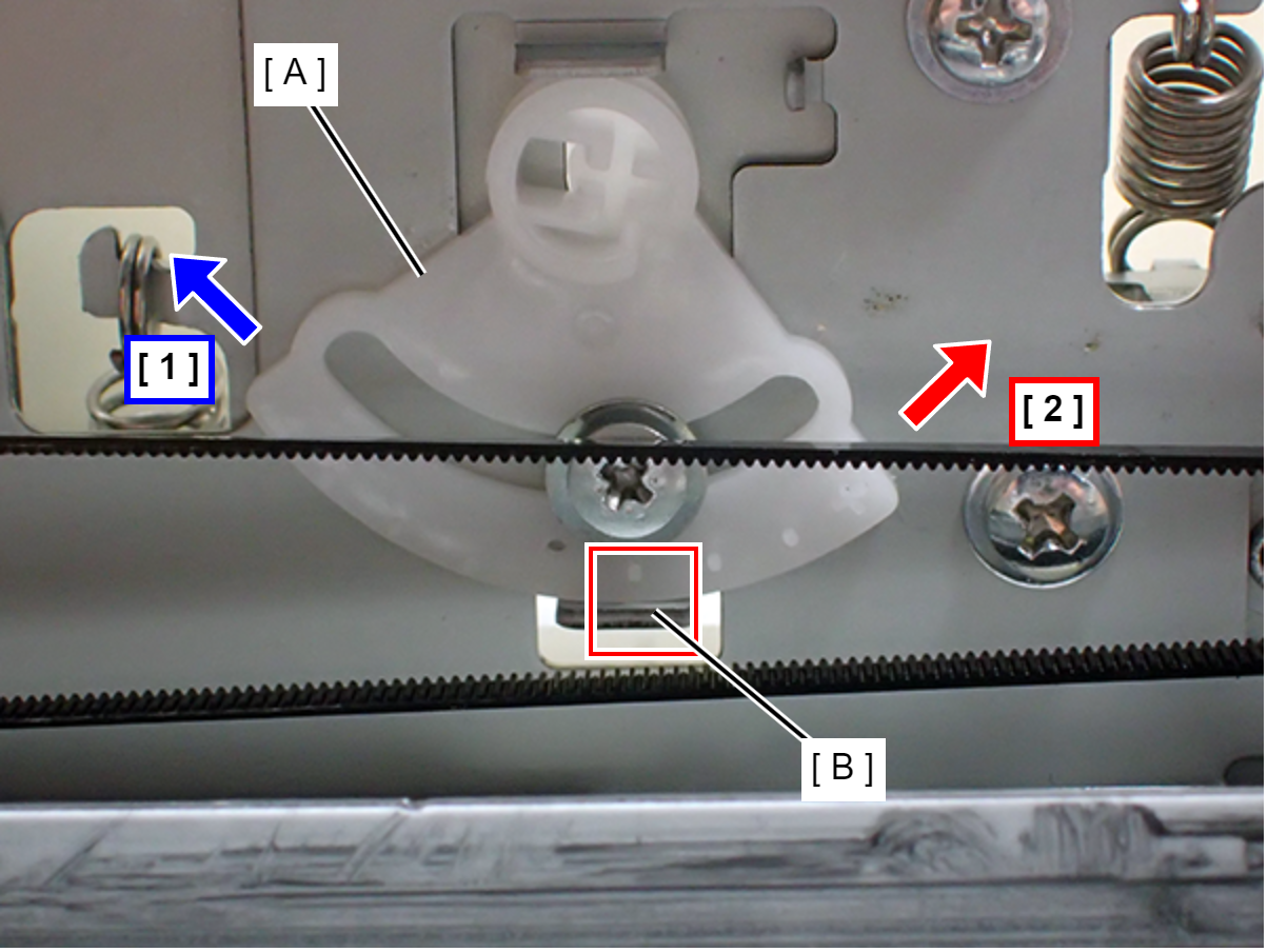
- 1: Larger PG
- 2: Smaller PG
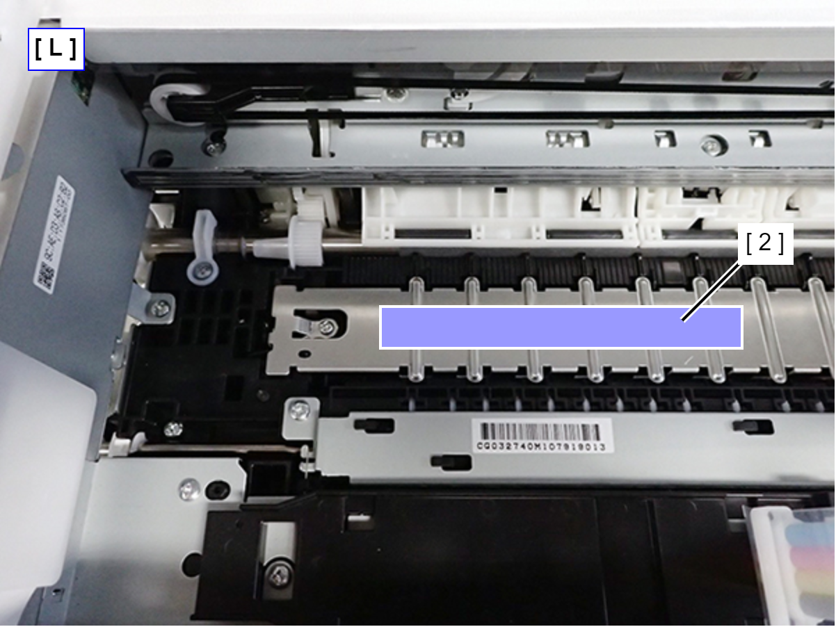
Place the thickness gauge (1.42 mm thickness gauge + 0.08 mm Teflon tape) at position (2) shown below. Even for the Full digit side (L), follow the same procedure to adjust the Left PG adjustment cam until the CR Unit comes in contact with the thickness gauge.
Place the thickness gauge (1.62 mm thickness gauge + 0.08 mm Teflon tape) at position (1) shown below.
Move the CR unit to the thickness gauge and check whether or not the CR Unit touches the thickness gauge.
If touches the thickness gauge: Proceed to step 9.
If does not touch the thickness gauge: Perform the adjustment in the procedure below. If it does not touch the thickness gauge even after adjustment, repeat the following steps until it touches the thickness gauge.
Move the CR unit to the center part of the printer.
Move the Right PG adjustment cam by one notch in the “-” direction.
Move the CR unit to the thickness gauge again and check whether or not the CR Unit touches the thickness gauge.
Place the thickness gauge (1.62 mm thickness gauge + 0.08 mm Teflon tape) at position (2) shown below. Even for the Full digit side, follow the same procedure to adjust the Left PG adjustment cam until the CR Unit comes in contact with the thickness gauge.
Tighten the four fixing screws of the CR guide frame (A).
Restore the Left PG adjustment cam and Right PG adjustment cam to their positions before adjustment, and tighten with fixing screws (×2).