Panel Assy
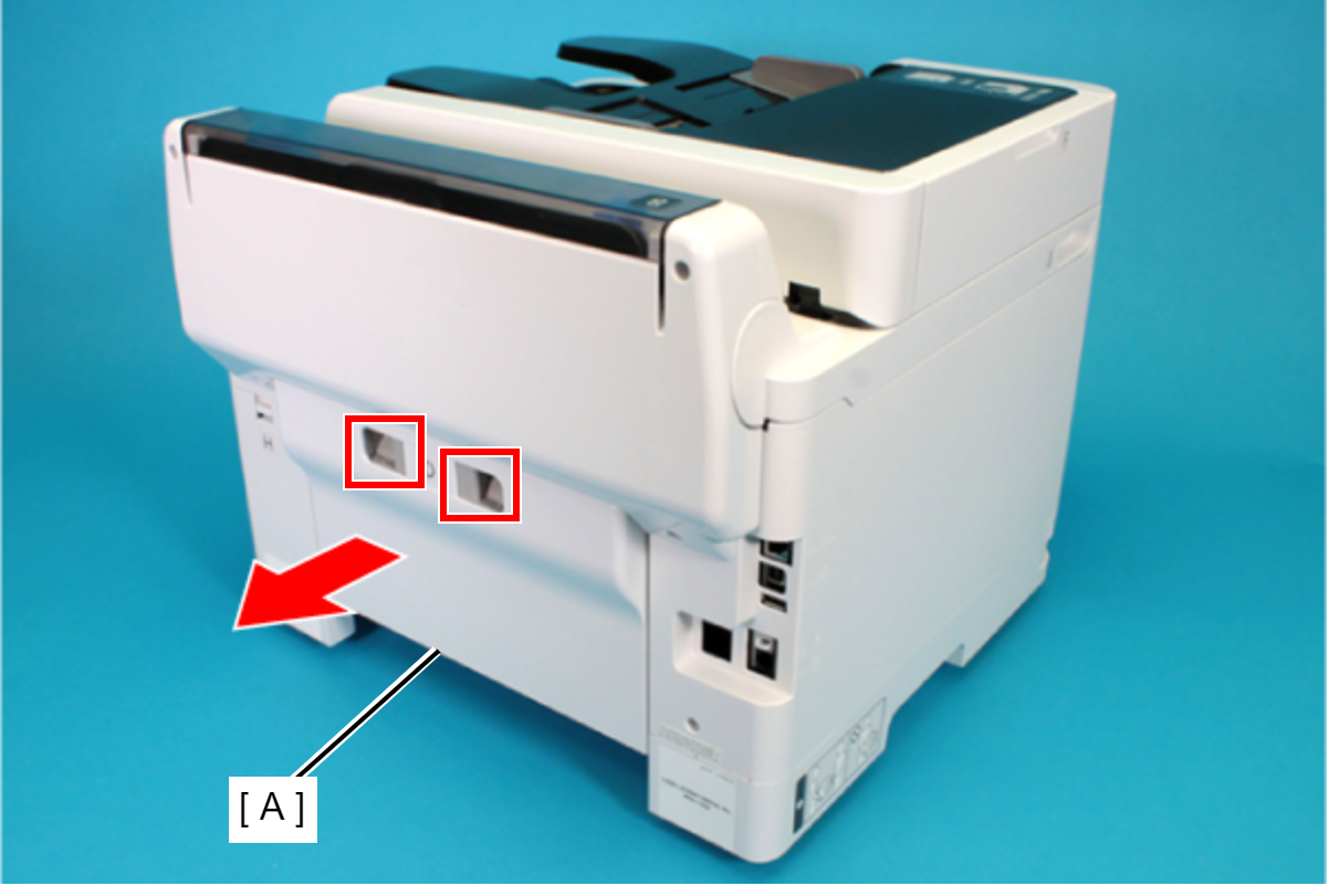
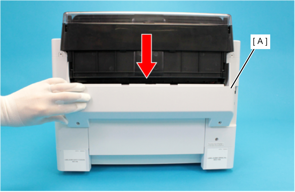
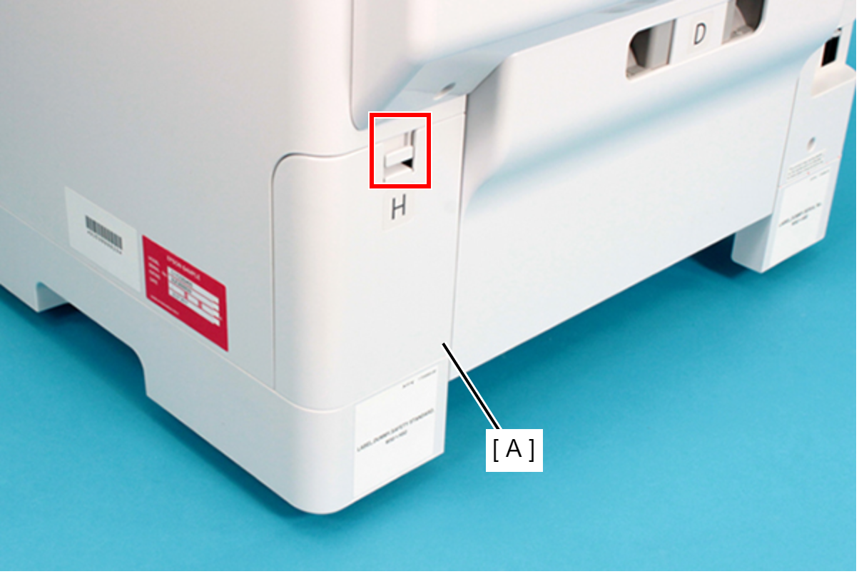
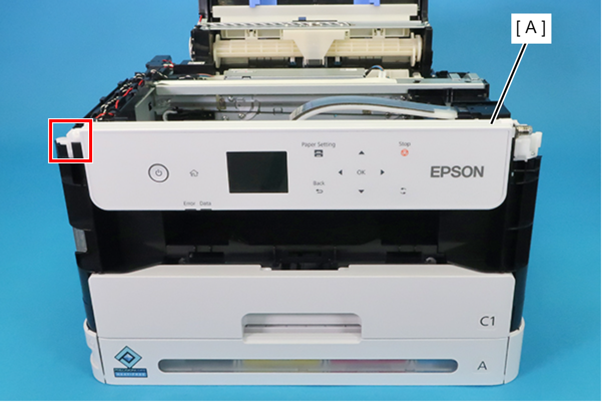
- Remove the Rear Unit (A) in the direction of the arrow while pressing the buttons inward.
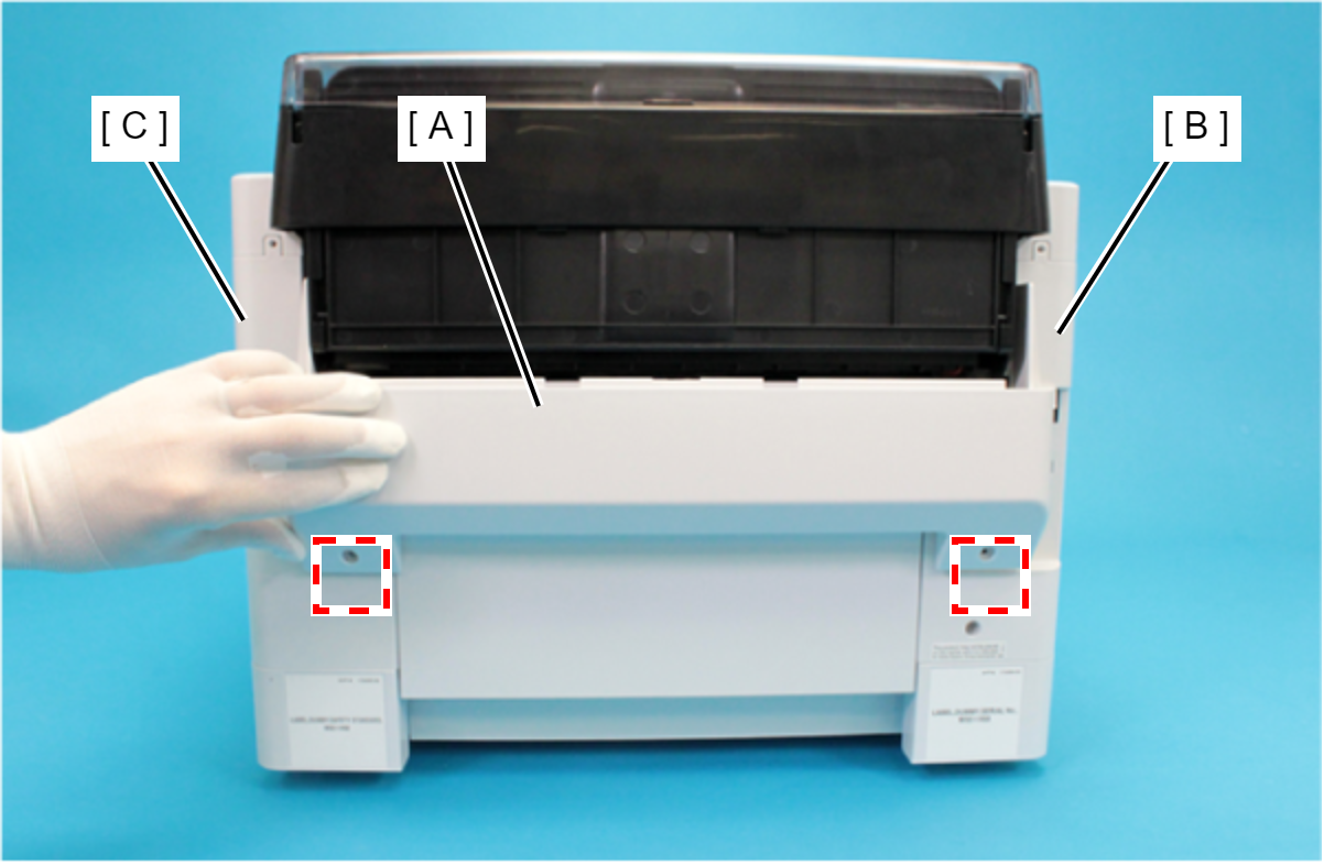
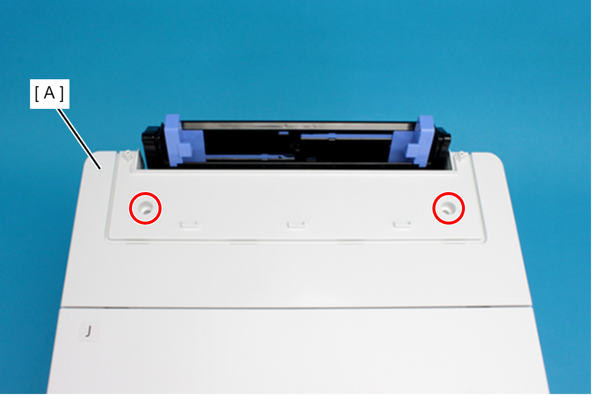
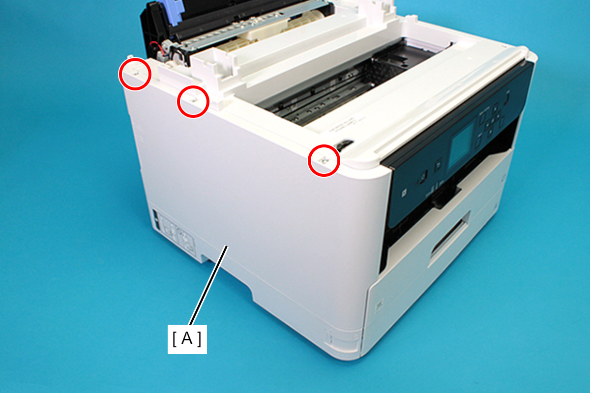
- Open the ASF Cover (A) and remove the two screws securing the Rear Housing Assy (B).
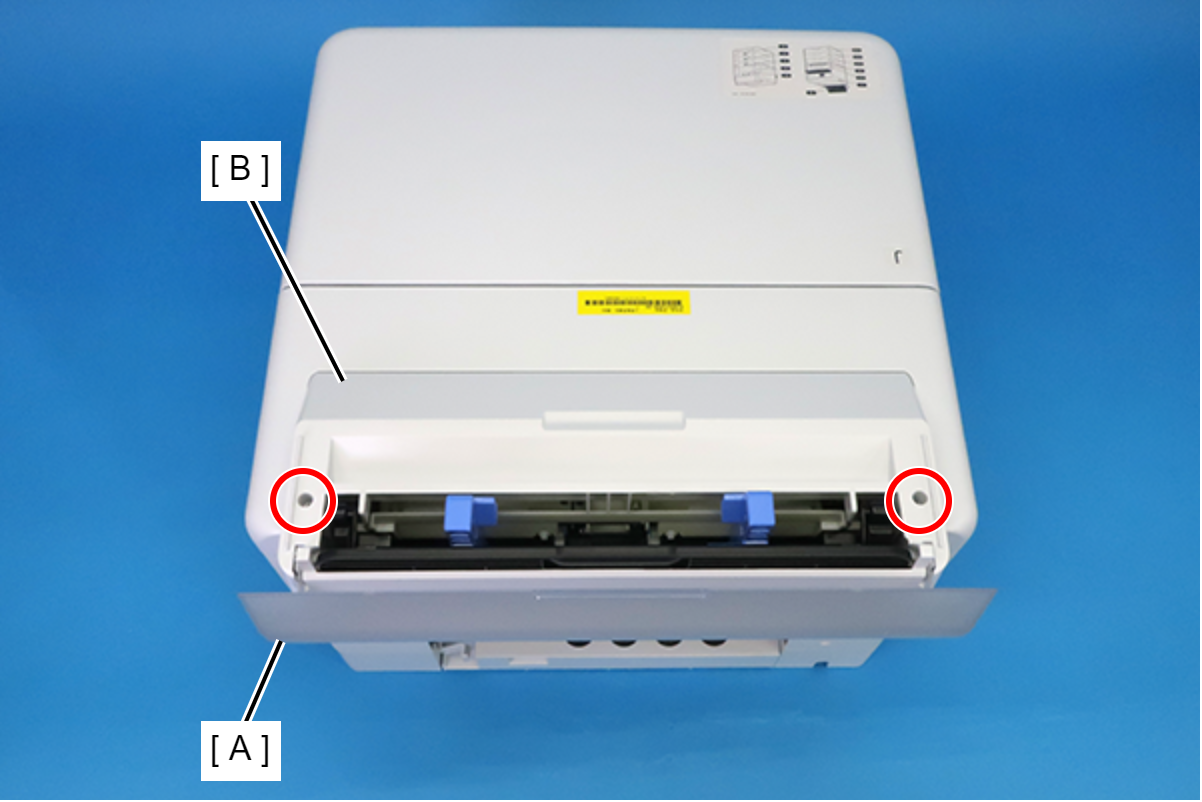
 : C.B.P-TITE-SCREW-3x10-F.ZB-3C
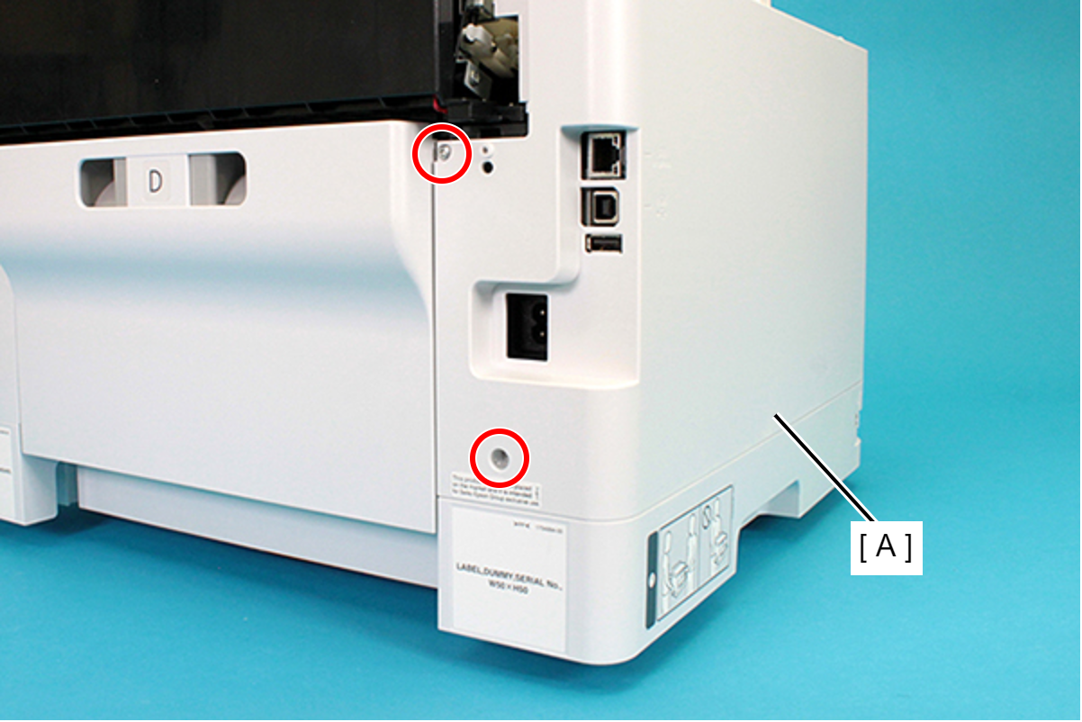
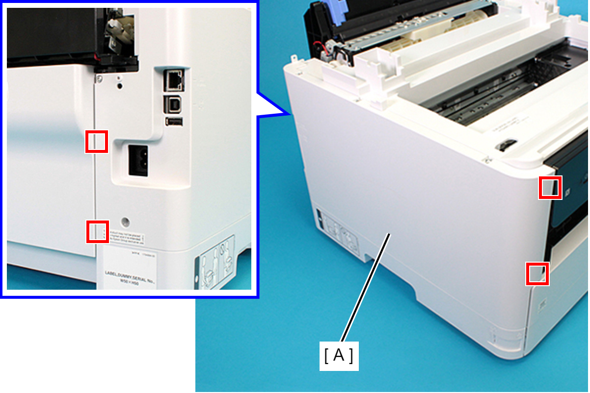
- Remove the four screws securing the Rear Housing (A).
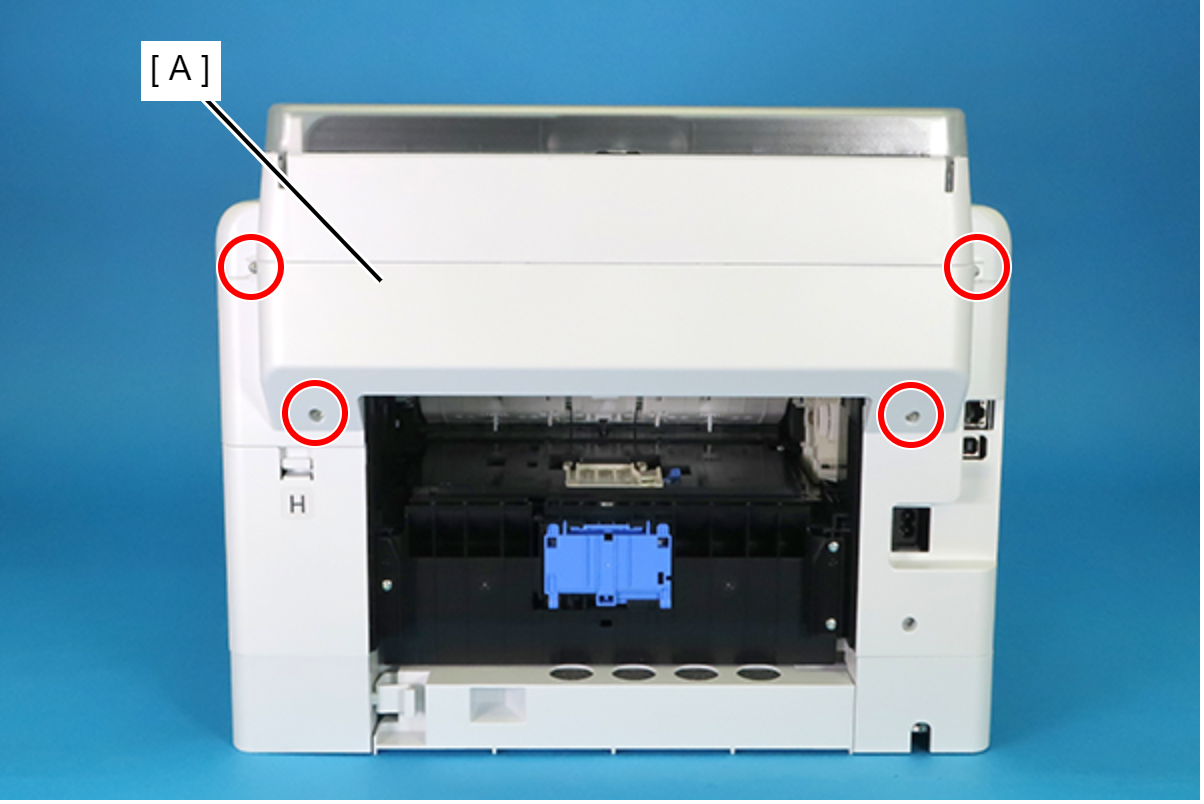
 : C.B.P-TITE-SCREW-3x10-F.ZN-3C
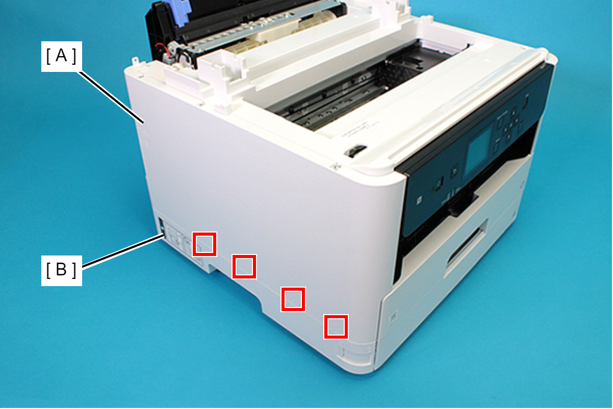
Remove the Rear Housing (A) downward.
 Assembly / 組み立て
Attach the two dowels of the Rear Housing (A) to the positioning holes on the Housing Left (B) and the Housing Right (C).
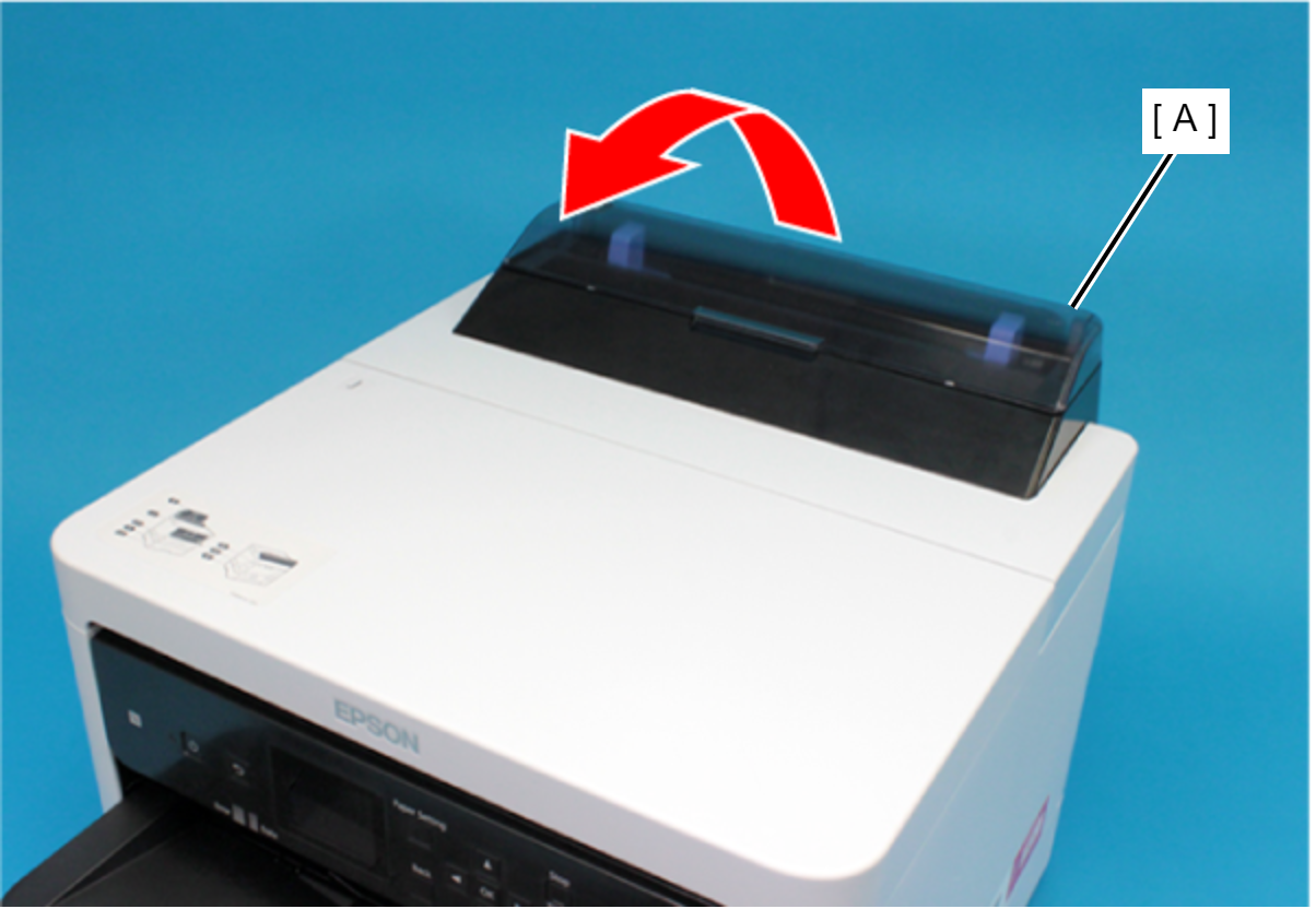
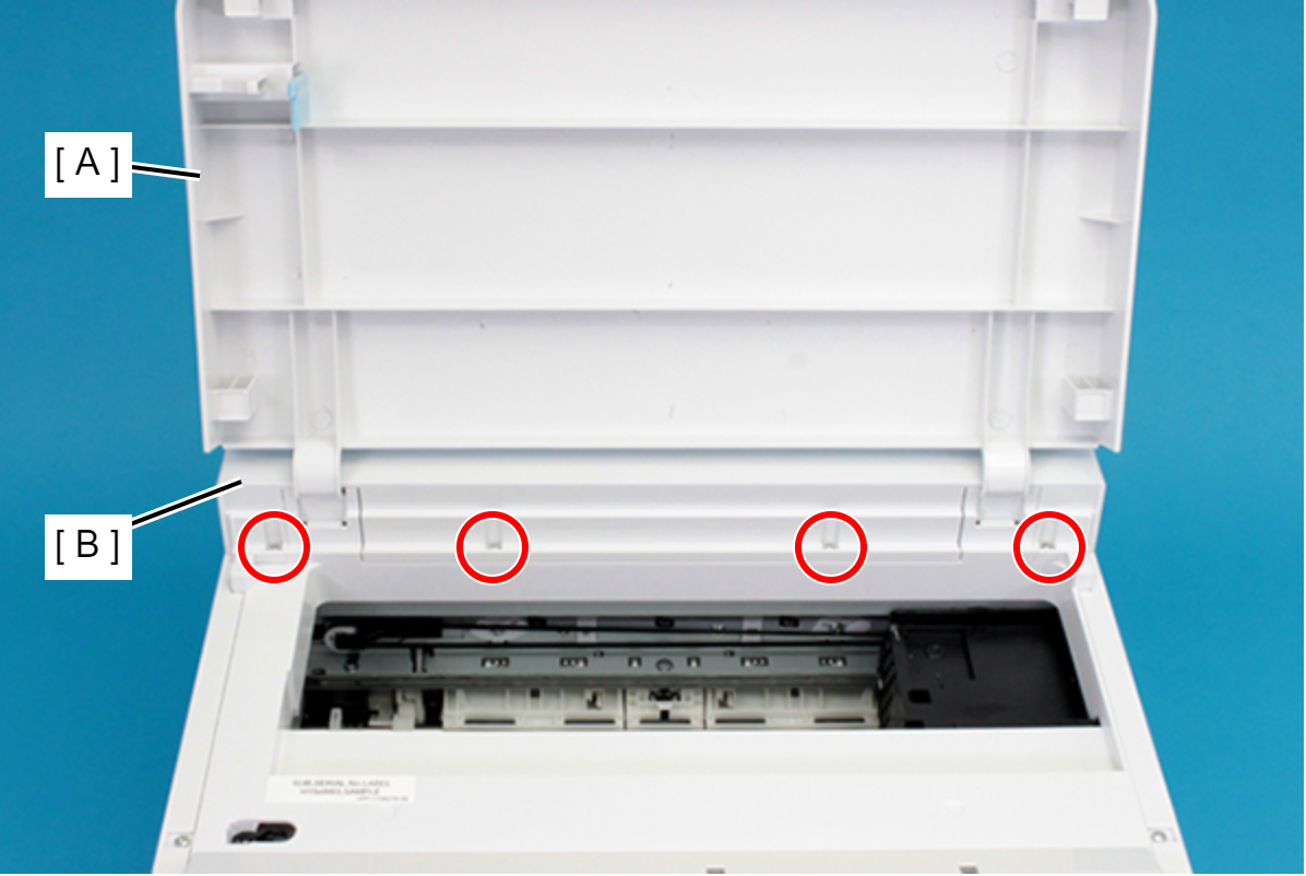
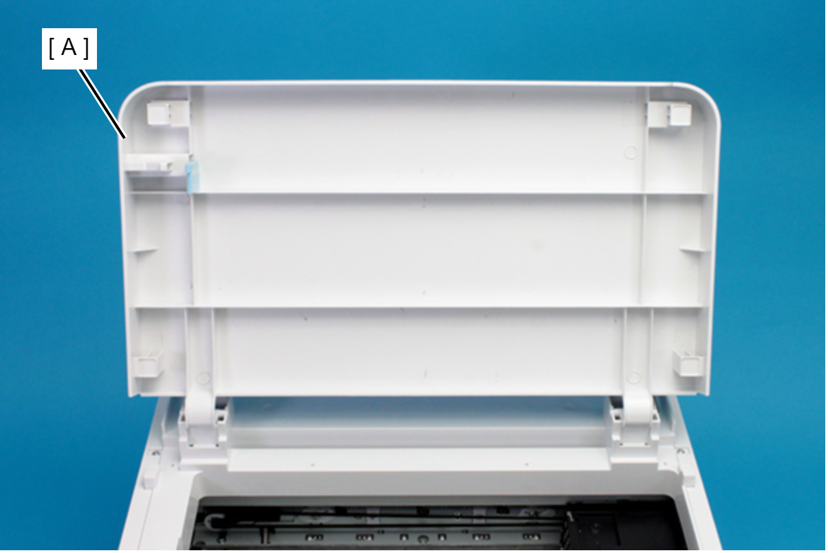
Remove the Rear Upper Cover Assy (A) in the direction of the arrow.
 Assembly / 組み立て
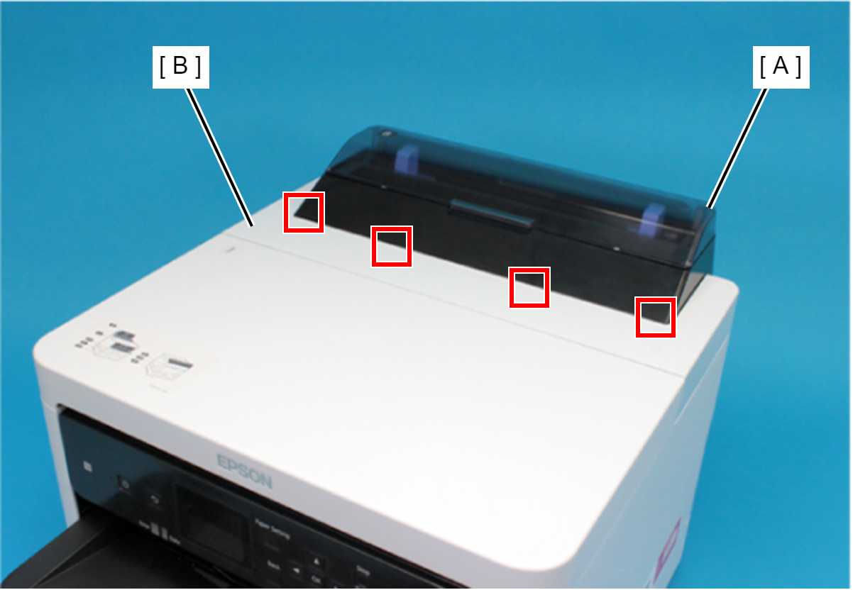
Insert the four tabs of the Rear Upper Cover Assy (A) to the positioning holes of the Housing ASF (B).
- Remove the two screws securing the Housing ASF (A).
- : C.B.P-TITE-SCREW-3x10-F.ZN-3C
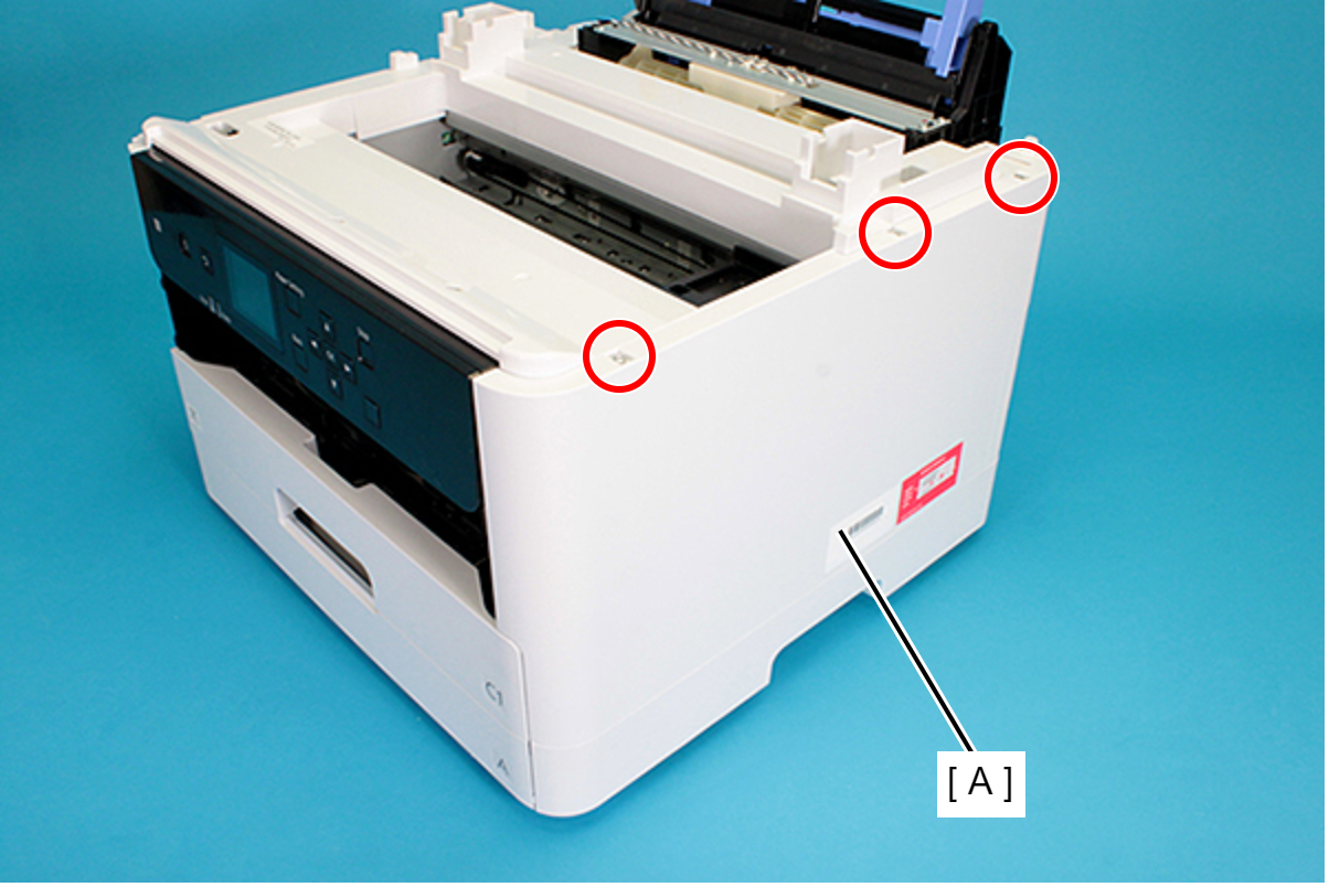
- Open the Printer Cover (A) and remove the four screws, and then remove the Housing ASF (B).
- : C.B.P-TITE-SCREW-3x10-F.ZN-3C
- Disengage the hook, and remove the Maintenance Box Cover (A).
- Remove the three screws securing the Housing Right (A).
- : C.B.P-TITE-SCREW-3x10-F.ZN-3C
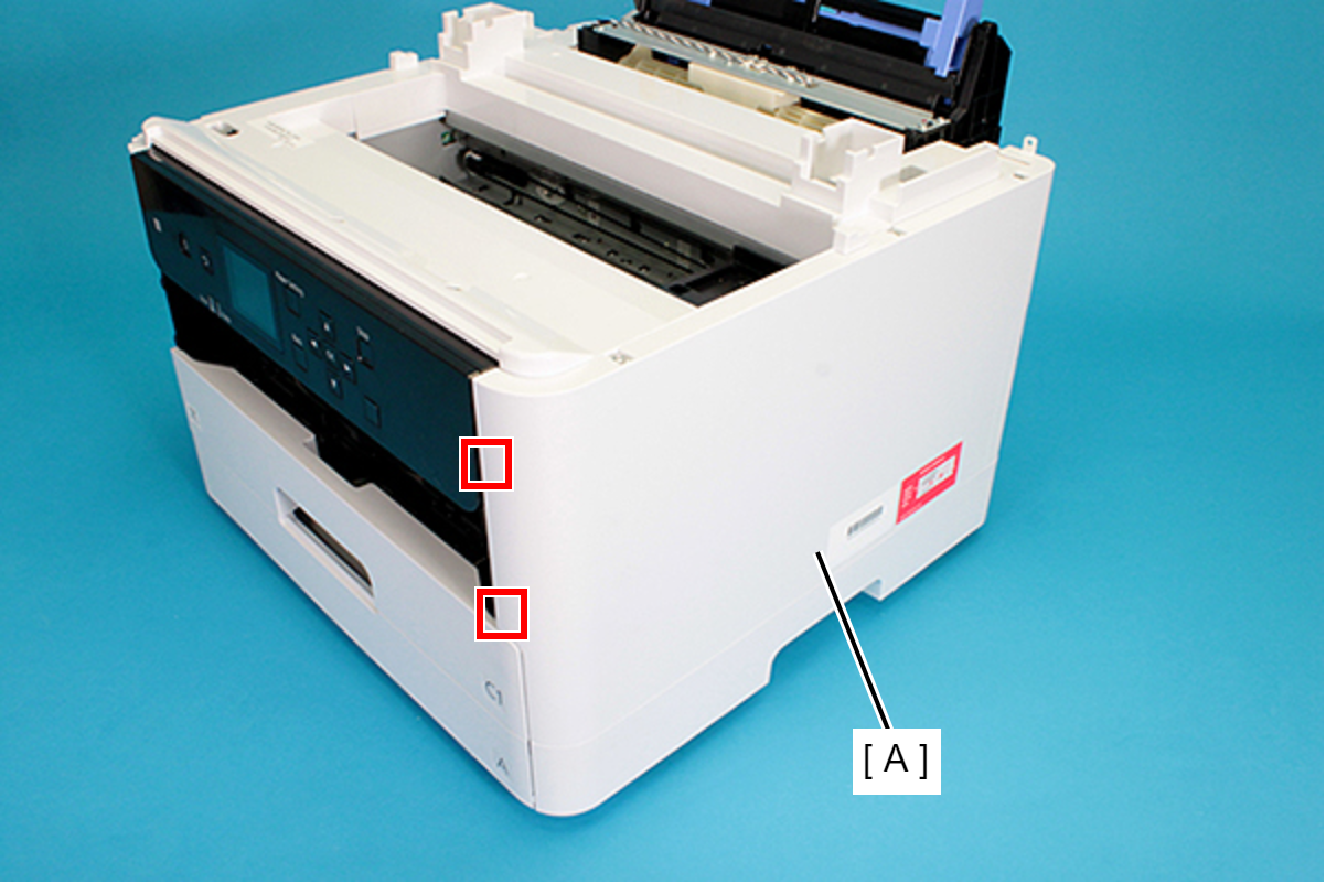
- Remove the two screws securing the Housing Right (A).
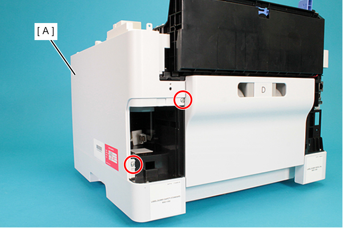
- : C.B.P-TITE-SCREW-3x10-F.ZN-3C
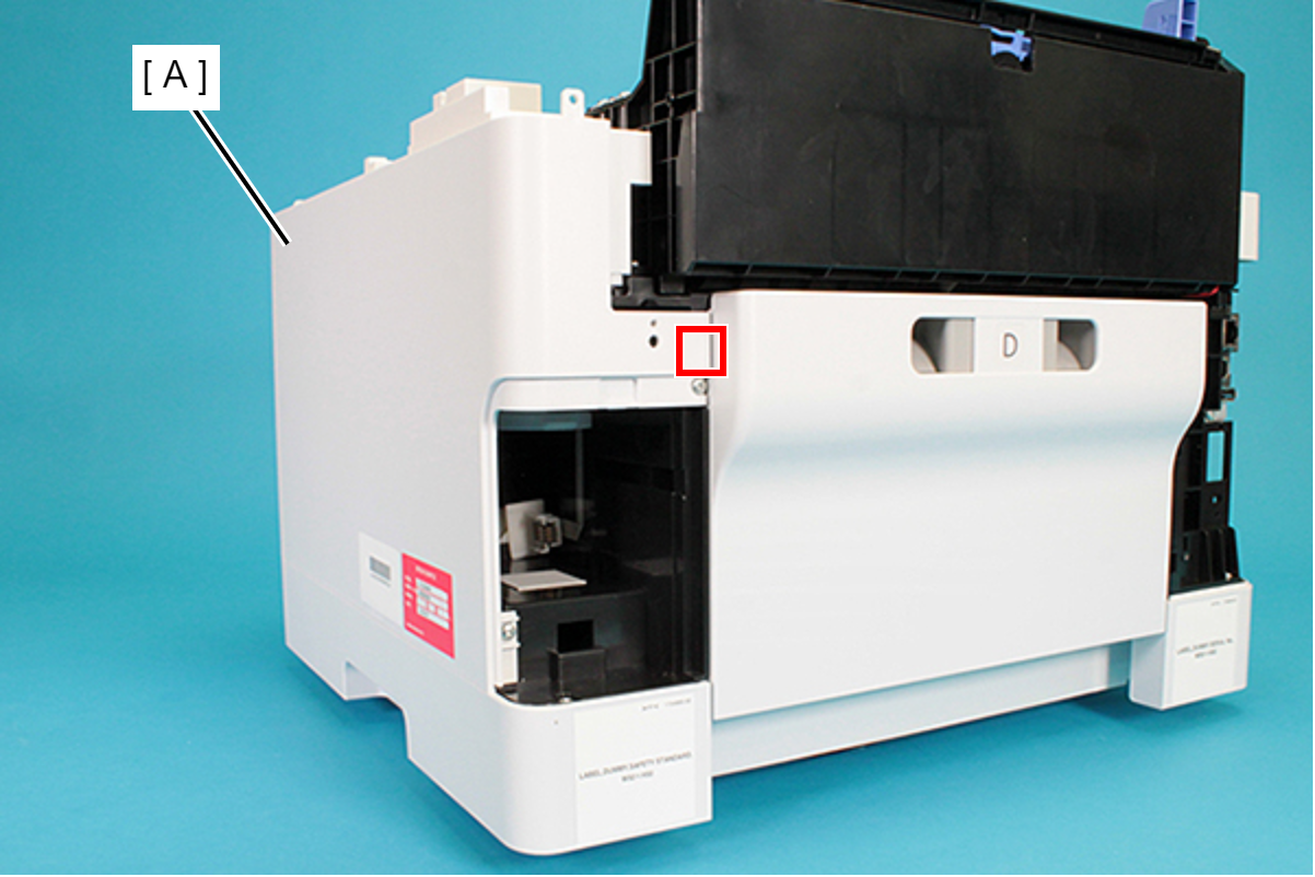
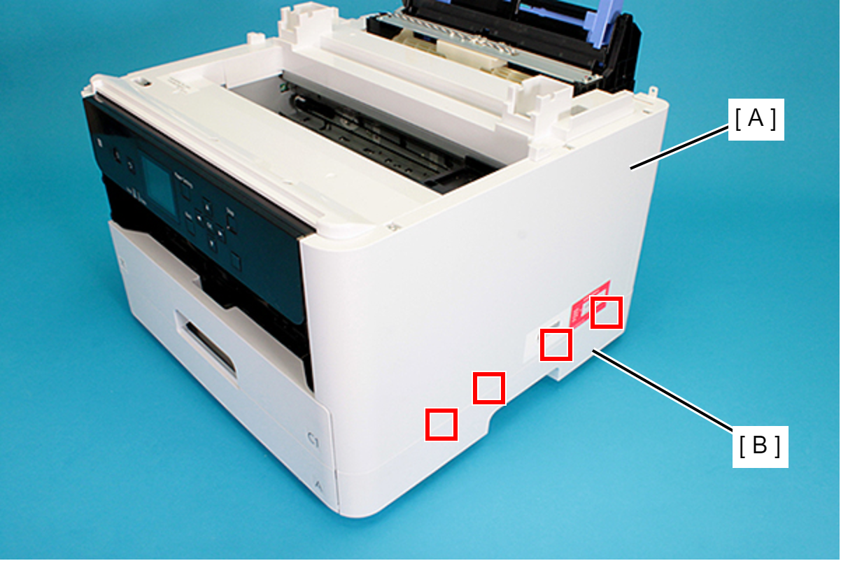
- Lift the Housing Right (A) upward to release the two hooks on the front side of the Housing Right (A).
Remove the dowels to the rear, and lift up the Housing Right (A) to remove it.
 Assembly / 組み立て
Insert the four tabs of the Housing Right (A) to the positioning holes of the RIPS Unit (B).
- Remove the three screws securing the Housing Left (A).
- : C.B.P-TITE-SCREW-3x10-F.ZN-3C
- Remove the two screws securing the Housing Left (A).
- : C.B.P-TITE-SCREW-3x10-F.ZN-3C
Lift the Housing Left (A) upward to release the two hooks each on the front side and rear side of the Housing Left (A), and then remove the Housing Left (A).
 Assembly / 組み立て
Insert the four tabs of the Housing Left (A) to the positioning holes of the RIPS Unit (B).
- Remove the Printer Cover (A) upward.
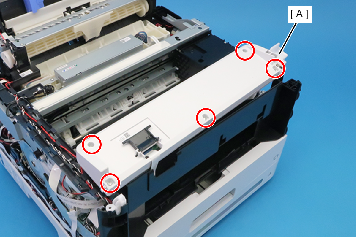
- Remove the seven screws and remove the Housing Top (A).
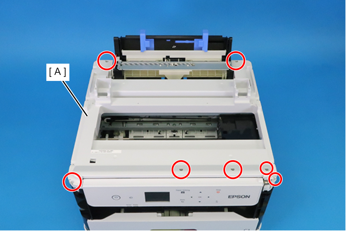
- : C.B.P-TITE-SCREW-3x10-F.ZN-3C
- Remove the two screws, then remove the Right Panel Holder (A).
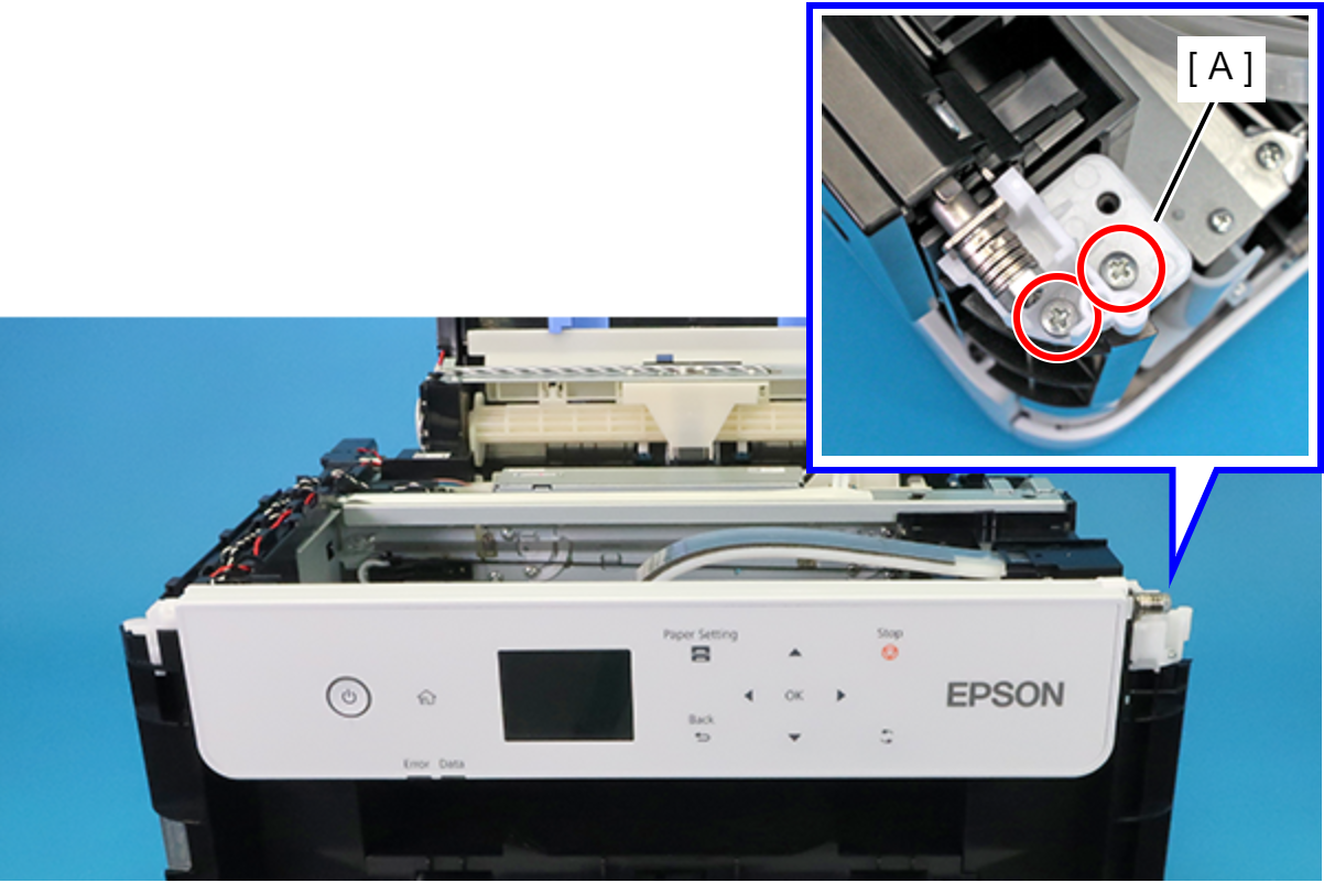
- : C.B.P-TITE-SCREW-3x10-F.ZN-3C
 Caution / 注意
The FFC (B) is connected to the interior of the Panel Assy (A).
Accordingly, when using the following procedure to remove the Panel Assy (A), ensure that it is not pulled excessively.
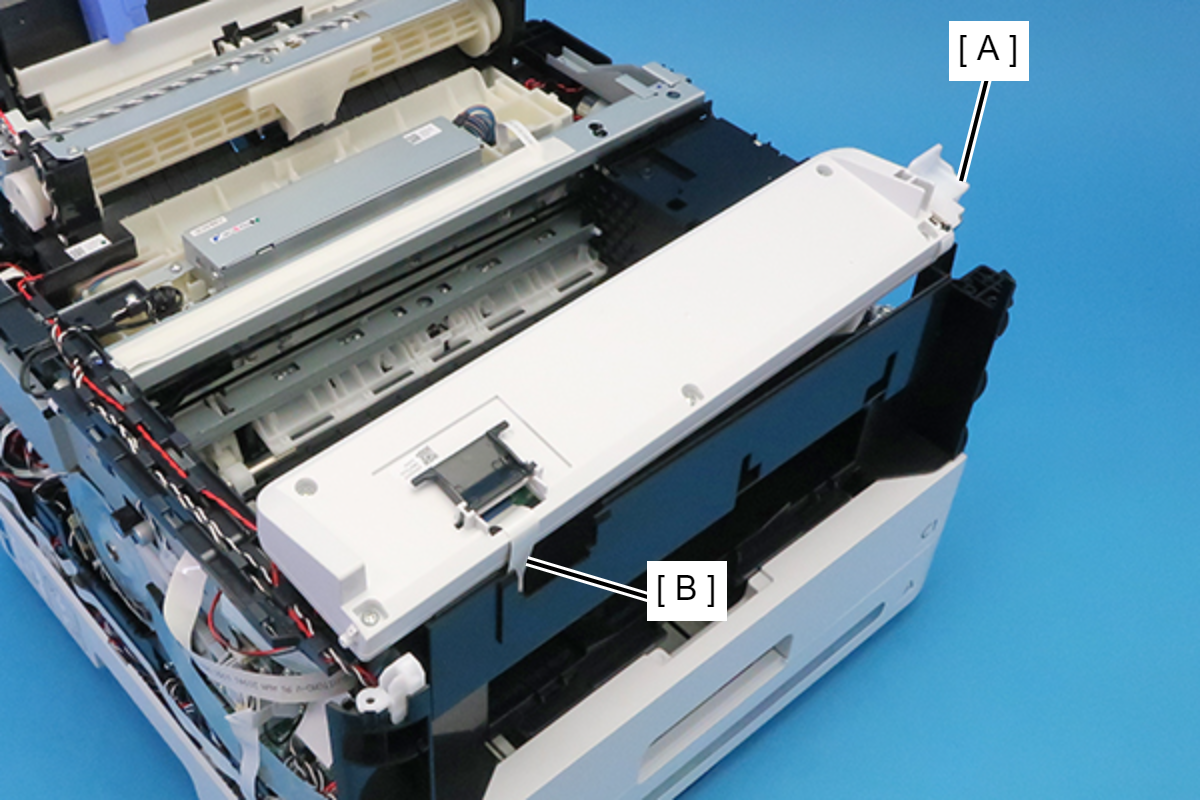
Release the shaft of the Panel Assy (A) from the bearing, then remove the Panel Assy (A).
 Caution / 注意
When using the following procedure to place the Panel Assy, take care not to scratch the front surface of the Panel Assy.
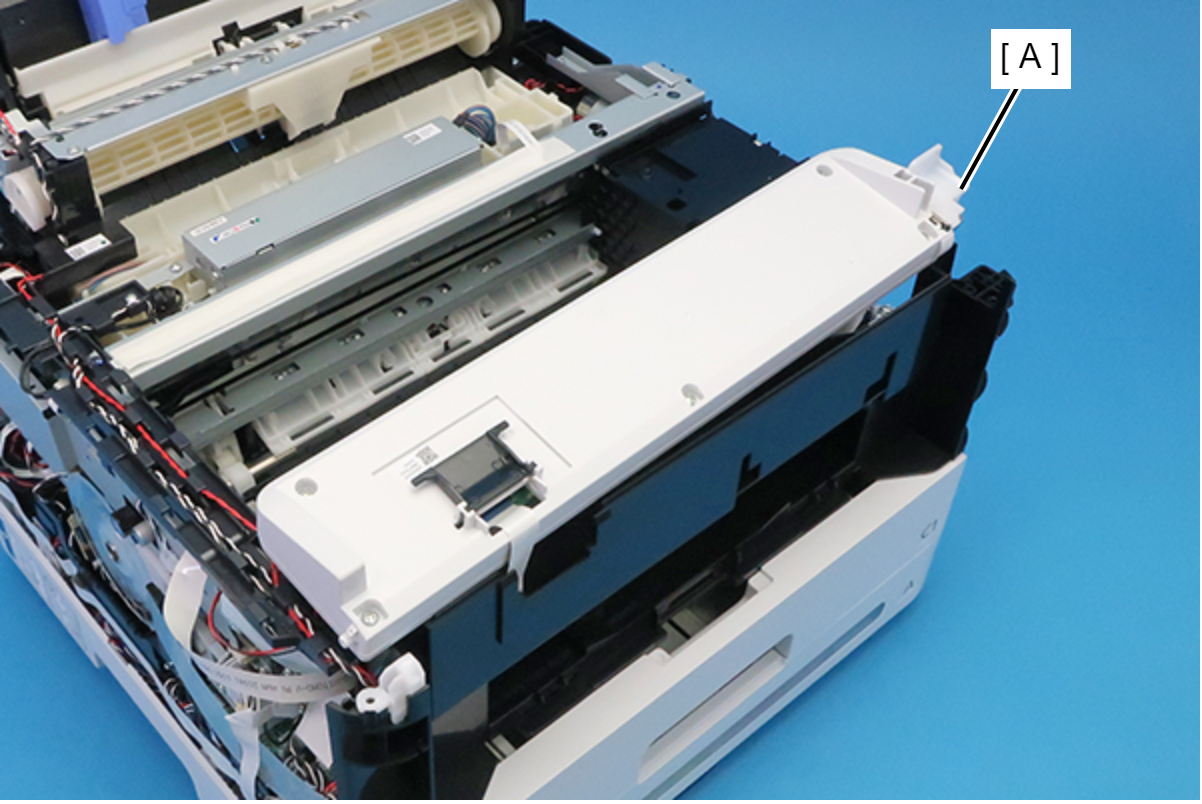
- Turn the Panel Assy (A) over and place it on top of the printer.
- Remove the five screws securing the Panel Housing (A).
- : C.B.P-TITE-SCREW-3x10-F.ZN-3C
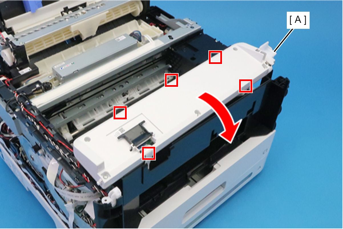
- Disengage the five hooks and open the Panel Housing (A) in the direction of the arrow.
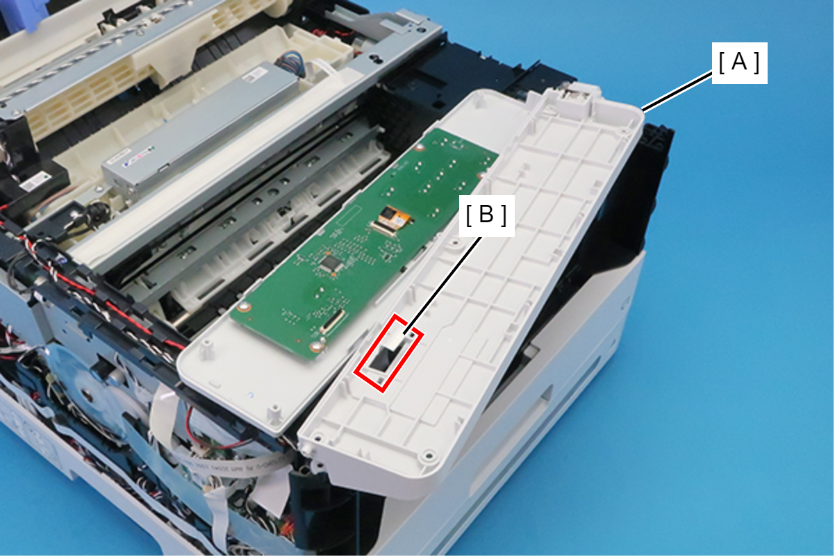
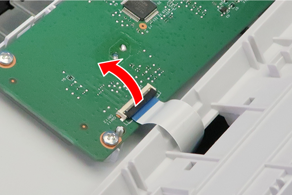
Release the connector lock, and disconnect the FFC (B) from the connector (CN111) on the Panel Board (A).
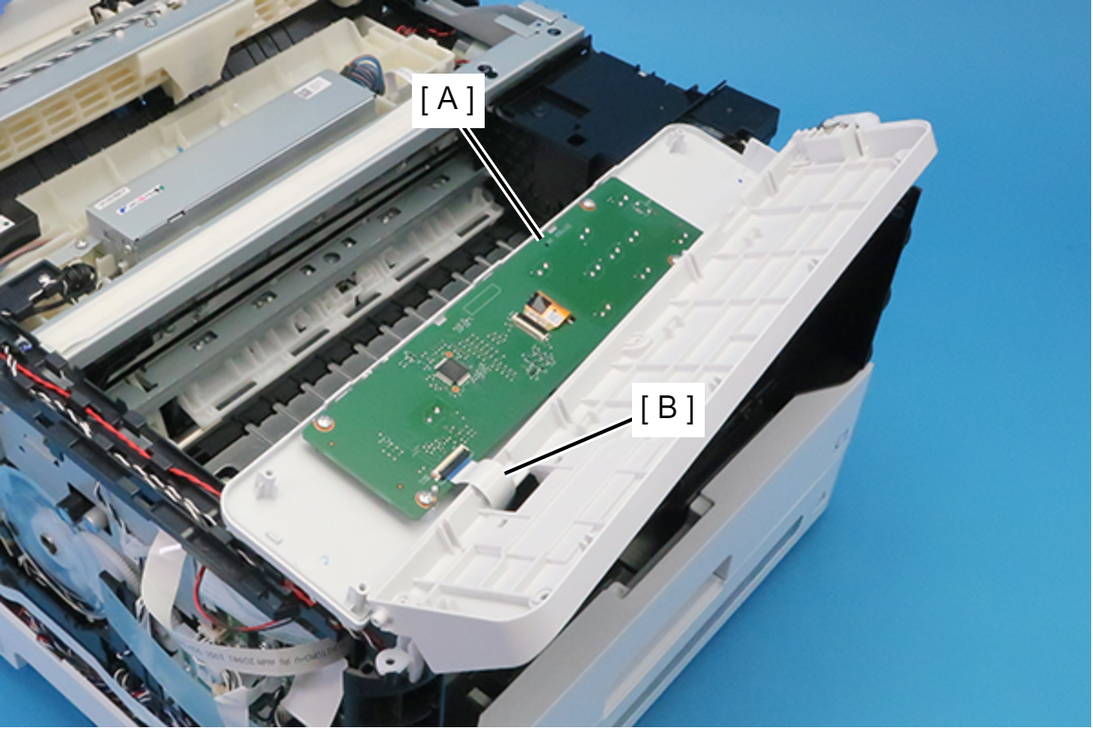
 Check Point / チェックポイント
Release the connector (CN111) on the Panel Board by opening the connector lock in the direction of the arrow.
Pull out the FFC (B) from the hole on the Panel Housing (A) to remove the Panel Assy.